

Page 1
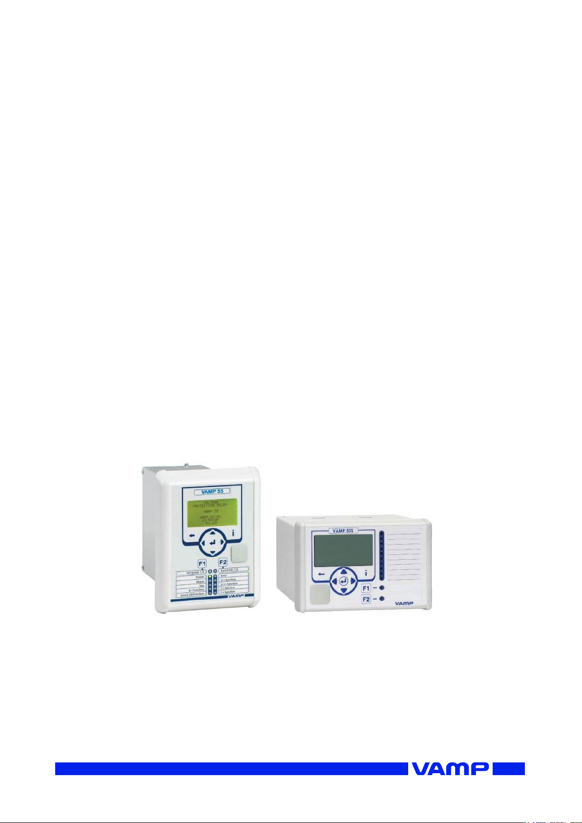
VAMP 55
Voltage and frequency protection relay
Operation and configuration
instructions
Technical description
Page 2

VM55.EN005
Page 3

Operation and configuration
Table of Contents
VM55.EN005
VAMP 24h support phone +358 (0)20 753 3264
3
Table of Contents
1. General ................................................................................... 4
1.1. Relay features ..................................................................... 4
1.2. User interface ...................................................................... 5
1.3. Operating Safety ................................................................ 5
2. Local panel user interface .................................................... 6
2.1. Relay front panel ................................................................ 6
2.1.1. Display ......................................................................... 7
2.1.2. Menu navigation and pointers ................................ 8
2.1.3. Keypad ........................................................................ 9
2.1.4. Operation indicators .............................................. 10
2.1.5. Adjusting display contrast ..................................... 11
2.2. Local panel operations .................................................. 11
2.2.1. Navigating in menus .............................................. 11
2.2.2. Menu structure of protection functions .............. 14
2.2.3. Setting groups ......................................................... 18
2.2.4. Fault logs .................................................................. 19
2.2.5. Operating levels ...................................................... 20
2.3. Operating measures ....................................................... 22
2.3.1. Control functions .................................................... 22
2.3.2. Measured data ....................................................... 23
2.3.3. Reading event register .......................................... 24
2.3.4. Forced control (Force) ........................................... 25
2.4. Configuration and parameter setting ......................... 26
2.4.1. Parameter setting ................................................... 27
2.4.2. Setting range limits ................................................. 28
2.4.3. Disturbance recorder menu DR ........................... 28
2.4.4. Configuring digital inputs DI .................................. 29
2.4.5. Configuring digital outputs DO ............................ 29
2.4.6. Configuring analogue outputs AO (Option) ...... 30
2.4.7. Protection menu Prot ............................................. 30
2.4.8. Configuration menu CONF ................................... 31
2.4.9. Protocol menu Bus .................................................. 32
2.4.10. Single line diagram editing ................................... 35
2.4.11. Blocking and interlocking configuration ............. 35
3. VAMPSET PC software .......................................................... 36
Page 4
1.1 Relay features
1 General
Operation and configuration
4
VAMP 24h support phone +358 (0)20 753 3264
VM55.EN005
IEEE/ANSI
code
IEC symbol
Function name
59
U>, U>>,
U>>>
Overvoltage protection
24
U/f>
Volts/hertz over excitation
protection
27P
U1<, U1<<
Positive sequence undervoltage
protection for generator
applications
27
U<, U<<,
U<<<
Undervoltage protection
59N
U0>, U0>>
Zero sequence voltage protection
81H/81L
f><, f>><<
Overfrequency and underfrequency
protection
81L
f<, f<<
Underfrequency protection
25
∆f, ∆U, ∆φ
Synchrocheck
1. General
This first part (Operation and configuration) of the publication
contains general descriptions of the functions, of the protection
relay as well as operation instructions. It also includes
instructions for parameterization and configuration of the relay
and instructions for changing settings.
The second part (Technical description) of the publication
includes detailed protection function descriptions as well as
application examples and technical data sheets.
The Mounting and Commissioning Instructions are published
in a separate publication with the code VMMC.EN0xx.
1.1. Relay features
The VAMP 55 protection relay concept has two alternative
casing layout designs: basic and slim fit.
The VAMP 55S includes more compact casing than in the basic
design. In the VAMP 55S, the same protection, measurement
and control functions and communication interfaces are
supported as in the basic 55 relays.
The comprehensive protection functions of the relay make it
ideal for utility, industrial, marine and off-shore power
distribution applications. The relay features the following
protection functions.
List of protection functions
Page 5
Operation and configuration
1 General
1.2 User interface
VM55.EN005
VAMP 24h support phone +358 (0)20 753 3264
5
IEEE/ANSI
code
IEC symbol
Function name
50BF
CBFP
Circuit-breaker failure protection
99
Prg1…8
Programmable stages
Further the relay includes a disturbance recorder.
The relay communicates with other systems using common
protocols, such as the Modbus RTU, ModbusTCP, Profibus DP,
IEC 60870-5-103, IEC 60870-5-101, IEC 61850, SPA bus, and
DNP 3.0. An optional communication option is required for
this (see ordering code in technical description).
1.2. User interface
The relay can be controlled in three ways:
Locally with the push-buttons on the relay front panel
Locally using a PC connected to the USB port on the front
Via remote control over the optional remote control port on
the relay rear panel.
1.3. Operating Safety
The terminals on the rear panel of the relay may
carry dangerous voltages, even if the auxiliary
voltage is switched off. A live current transformer
secondary circuit must not be opened.
Disconnecting a live circuit may cause dangerous
voltages! Any operational measures must be carried out
according to national and local handling directives and
instructions.
Carefully read through all operation instructions before any
operational measures are carried out.
Page 6
2.1 Relay front panel
2 Local panel user interface
Operation and configuration
6
VAMP 24h support phone +358 (0)20 753 3264
VM55.EN005
2. Local panel user interface
2.1. Relay front panel
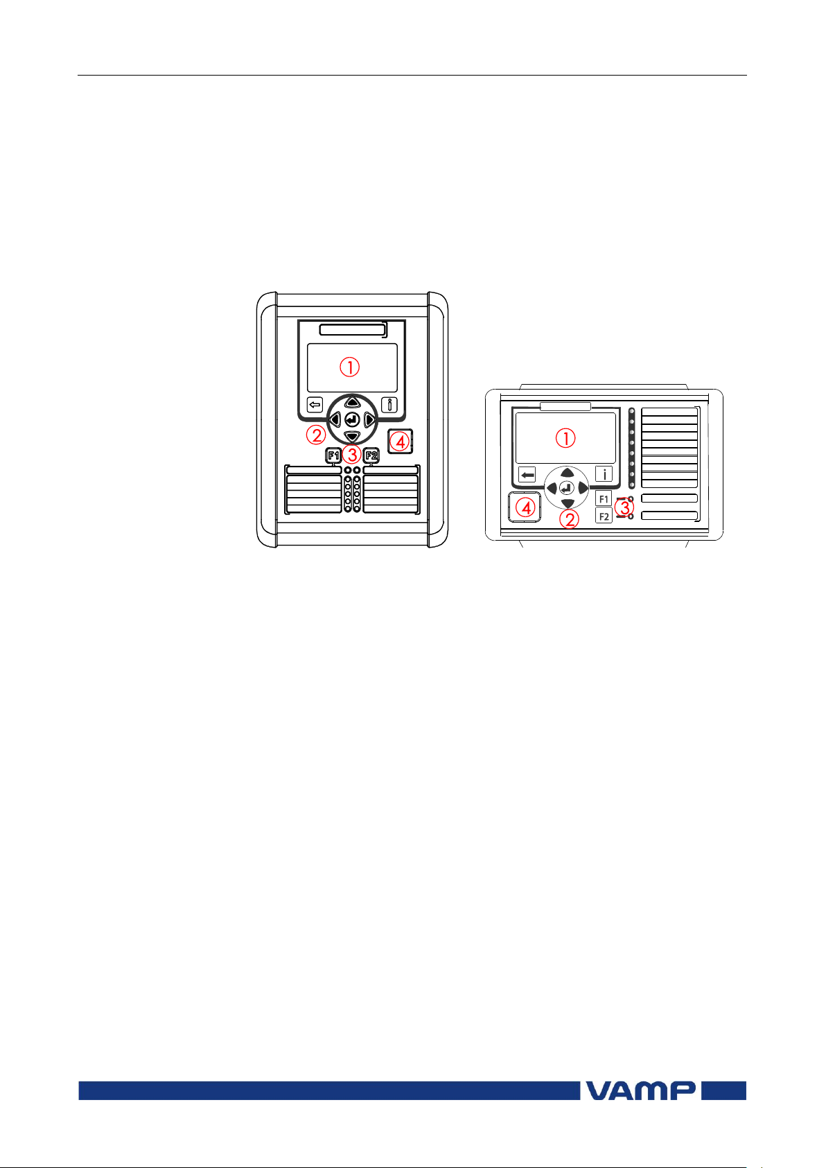
The figure below shows, as an example, the front panel of the
voltage and frequency protection relay VAMP 55 and the
location of the user interface elements used for local control.
Figure 2.1-1. Relay front panel
1. LCD dot matrix display
2. Keypad
3. LED indicators
4. USB communication port for PC
Page 7
Operation and configuration
2 Local panel user interface
2.1 Relay front panel
VM55.EN005
VAMP 24h support phone +358 (0)20 753 3264
7
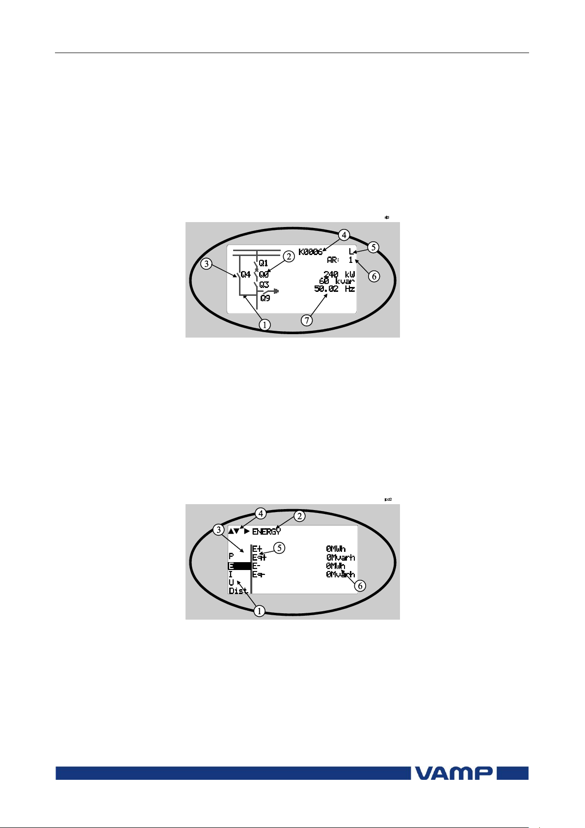
2.1.1. Display
The relay is provided with a backlighted 128x64 LCD dot
matrix display. The display enables showing 21 characters is
one row and eight rows at the same time. The display has two
different purposes: one is to show the single line diagram of the
relay with the object status, measurement values, identification
etc. (Figure 2.1.1-1). The other purpose is to show the
configuration and parameterization values of the relay (Figure
2.1.1-2).
Figure 2.1.1-1 Sections of the LCD dot matrix display
1. Freely configurable single-line diagram
2. Controllable objects (max six objects)
3. Object statuses (max eight objects)
4. Bay identification
5. Local/Remote selection
6. Auto-reclose on/off selection (if applicable)
7. Freely selectable measurement values (max. six values)
Figure 2.1.1-2 Sections of the LCD dot matrix display
1. Main menu column
2. The heading of the active menu
3. The cursor of the main menu
4. Possible navigating directions (push buttons)
5. Measured/setting parameter
6. Measured/set value
Page 8

2.1 Relay front panel
2 Local panel user interface
Operation and configuration
8
VAMP 24h support phone +358 (0)20 753 3264
VM55.EN005
Backlight control
Display backlight can be switched on with a digital input,
virtual input or virtual output. LOCALPANEL CONF/Display
backlight ctrl setting is used for selecting trigger input for
backlight control. When the selected input activates (rising
edge), display backlight is set on for 60 minutes.
2.1.2. Menu navigation and pointers
1. Use the arrow keys UP and DOWN to move up and down in
the main menu, that is, on the left-hand side of the display.
The active main menu option is indicated with a cursor. The
options in the main menu items are abbreviations, e.g. Evnt
= events.
2. After any selection, the arrow symbols in the upper left
corner of the display show the possible navigating directions
(applicable navigation keys) in the menu.
3. The name of the active submenu and a possible ANSI code
of the selected function are shown in the upper part of the
display, e.g. LINE VOLTAGES.
4. Further, each display holds the measured values and units
of one or more quantities or parameters, e.g. U12max 23000
V.
Page 9
Operation and configuration
2 Local panel user interface
2.1 Relay front panel
VM55.EN005
VAMP 24h support phone +358 (0)20 753 3264
9
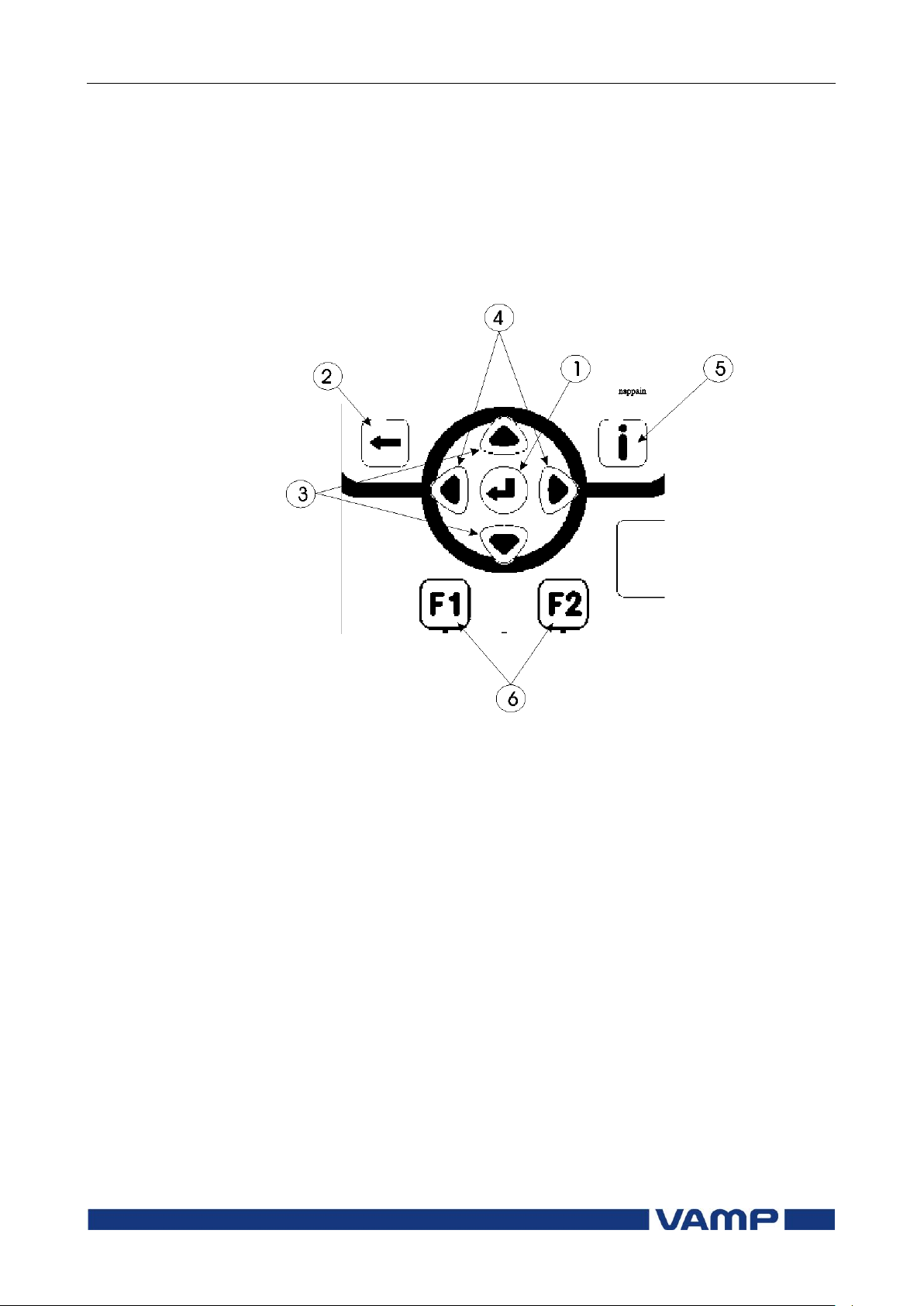
2.1.3. Keypad
You can navigate in the menu and set the required parameter
values using the keypad and the guidance given in the display.
Furthermore, the keypad is used to control objects and switches
on the single line diagram display. The keypad is composed of
four arrow keys, one cancel key, one enter key, one info key and
two configurable function keys.
Figure 2.1.3-1 Keys on the keypad
1. Enter and confirmation key (ENTER)
2. Cancel key (CANCEL)
3. Up/Down [Increase/Decrease] arrow keys (UP/DOWN)
4. Keys for selecting submenus [selecting a digit in a
numerical value] (LEFT/RIGHT)
5. Additional information key (INFO)
6. Function keys 1 and 2 (F1 / F2)
As default F1 toggles Virtual Input 1 (VI1) On/Off
As default F2 toggles Virtual Input 2 (VI2) On/Off
Instructions about programming F1 / F2, see chapter 5.4
Function keys / F1 & F2 in the technical description.
NOTE! The term, which is used for the buttons in this manual, is inside the
brackets.
Page 10
2.1 Relay front panel
2 Local panel user interface
Operation and configuration
10
VAMP 24h support phone +358 (0)20 753 3264
VM55.EN005
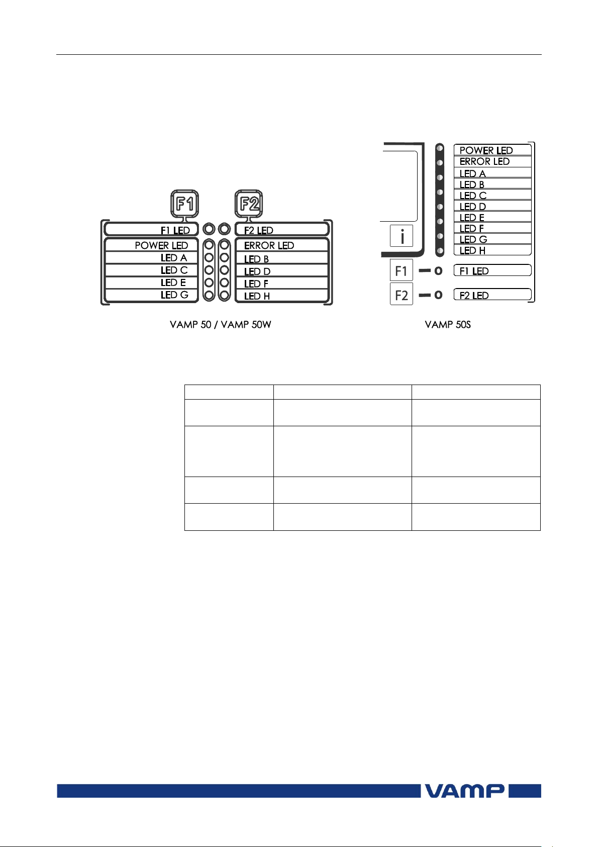
LED indicator
Meaning
Measure/ Remarks
Power LED lit
The auxiliary power has
been switched on
Normal operation state
Error LED lit
Internal fault, operates in
parallel with the self
supervision output relay
The relay attempts to
reboot [REBOOT]. If the
error LED remains lit,
call for maintenance.
A- H LED lit
Application-related status
indicators.
Configurable
F1 / F2 LED lit
Corresponding function
key pressed / activated
Depending of function
programmed to F1 / F2
2.1.4. Operation indicators
The relay is provided with twelve LED indicators:
Figure 2.1.4-1. Operation indicators of the relay
Resetting latched indicators and output relays
All the indicators and output relays can be given a latching
function in the configuration.
There are several ways to reset latched indicators and relays:
From the alarm list, move back to the initial display by
pushing the CANCEL key for approx. 3s. Then reset the
latched indicators and output relays by pushing the ENTER
key.
Acknowledge each event in the alarm list one by one by
pushing the ENTER key equivalent times. Then, in the
initial display, reset the latched indicators and output
relays by pushing the ENTER key.
The latched indicators and relays can also be reset via a remote
communication bus or via a digital input configured for that
purpose.
Page 11
Operation and configuration
2 Local panel user interface
2.2 Local panel operations
VM55.EN005
VAMP 24h support phone +358 (0)20 753 3264
11
Renaming LEDs
In VAMPSET software under the menu ”LED NAMES” it is
possible to assign custom name for each configurable LED.
2.1.5. Adjusting display contrast
The readability of the LCD varies with the brightness and the
temperature of the environment. The contrast of the display
can be adjusted via the PC user interface, see chapter 3.
2.2. Local panel operations
The front panel can be used to control objects, change the local/
remote status, read the measured values, set parameters, and
to configure relay functions. Some parameters, however, can
only be set by means of a PC connected to the local
communication port. Some parameters are factory-set.
2.2.1. Navigating in menus
All the menu functions are based on the main menu/submenu
structure:
1. Use the arrow keys UP and DOWN to move up and down in
the main menu.
2. To move to a submenu, repeatedly push the RIGHT key
until the required submenu is shown. Correspondingly,
push the LEFT key to return to the main menu.
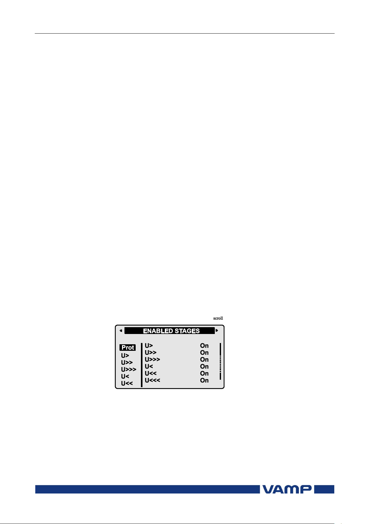
3. Push the ENTER key to confirm the selected submenu. If
there are more than six items in the selected submenu, a
black line appears to the right side of the display (Figure
2.2.1-1). It is then possible to scroll down in the submenu.
Figure 2.2.1-1 Example of scroll indication
4. Push the CANCEL key to cancel a selection.
5. Hold the CANCEL key pushed for appr. 4 sec. to display the
title screen.
6. Pushing the UP or DOWN key in any position of a
submenu, when it is not selected, brings you directly one
step up or down in the main menu.
Page 12
2.2 Local panel operations
2 Local panel user interface
Operation and configuration
12
VAMP 24h support phone +358 (0)20 753 3264
VM55.EN005
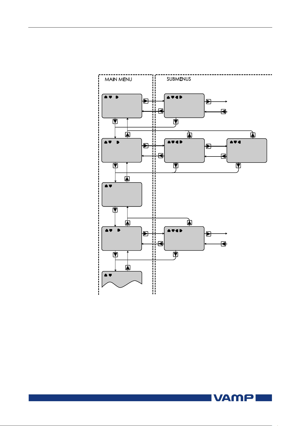
The active main menu selection is indicated with black
background color. The possible navigating directions in the
menu are shown in the upper-left corner by means of black
triangular symbols.
Figure 2.2.1-2 Principles of the menu structure and navigation in the menus
7. Push the INFO key and then the ENTER key to give the
password.
8. Push the INFO key to obtain additional information about
any menu item.
9. Push the CANCEL key to revert to the normal display.
Page 13
Operation and configuration
2 Local panel user interface
2.2 Local panel operations
VM55.EN005
VAMP 24h support phone +358 (0)20 753 3264
13
Main menu
Number
of
menus
Description
ANSI
code
Note
1 Interactive mimic display
1
5 Double size measurements
defined by the user
1
1 Title screen with device name,
time and firmware version.
U
19
Voltage measurements
Umax
9
Time stamped min & max of
voltages
Evnt
2
Events
DR 3 Disturbance recorder
2
Runh
2
Running hour counter. Active
time of a selected digital input
and time stamps of the latest
start and stop.
TIMR
6
Day and week timers
DI 5 Digital inputs including virtual
inputs
DO 4 Digital outputs (relays) and
output matrix
ExtAI
External analogue inputs
3 ExDI
External digital inputs
3 ExDO
External digital outputs
3
Prot
18
Protection counters, combined
overcurrent status, protection
status, protection enabling, and
block matrix
U> 4 1st overvoltage stage
59 4 U>>
3
2nd overvoltage stage
59 4 U>>>
3
3rd overvoltage stage
59 4 Uf>
3
Overexcitation stage volt/hertz
24
4
U1<
4
1st positive sequence
undervoltage stage
27P
4
U1<<
4
2nd positive sequence
undervoltage stage
27P
4
U< 4 1st undervoltage stage
27 4 U<<
3
2nd undervoltage stage
27 4 U<<<
3
3rd undervoltage stage
27
4
Uo>
3
1st residual overvoltage stage
59N
4
Uo>>
3
2nd residual overvoltage stage
59N
4
Main menu
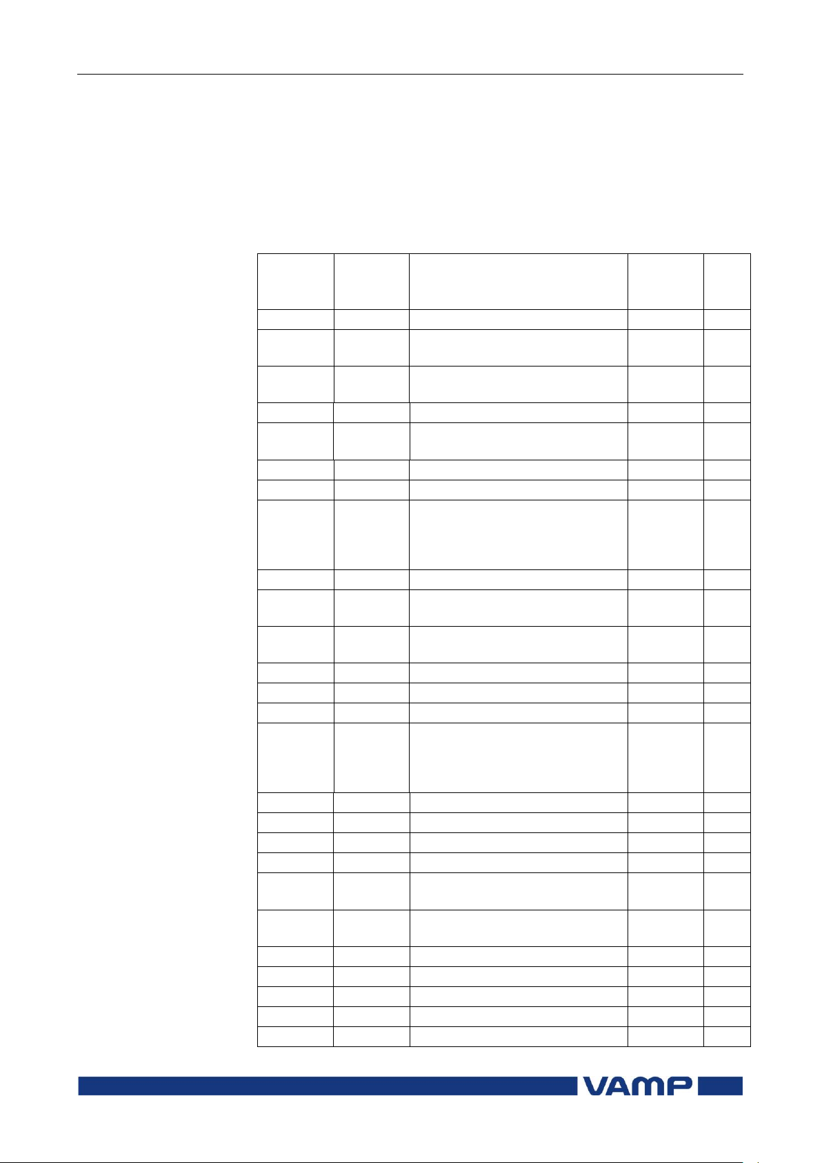
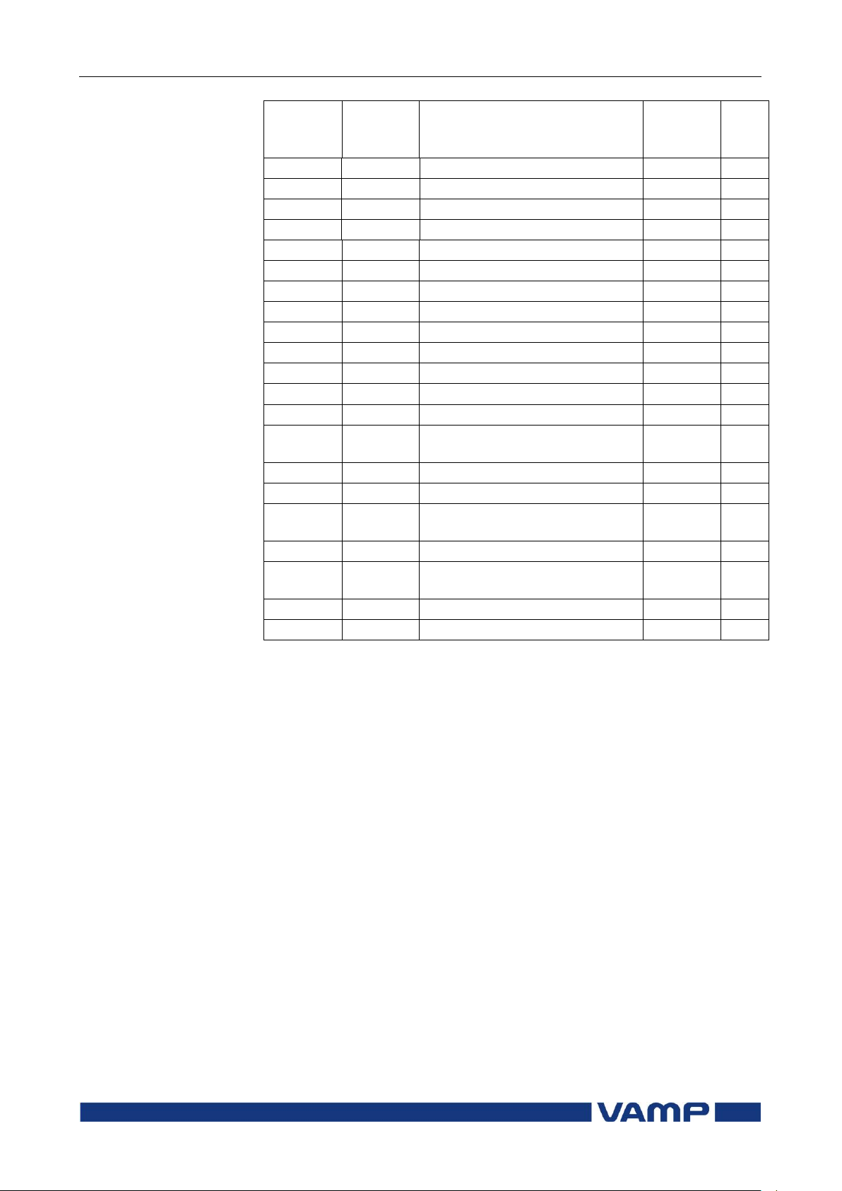
The general menu structure is shown in Figure 2.2.1-2. The
menu is dependent on the user’s configuration and the options
according the order code. For example only the enabled
protection stages will appear in the menu.
A list of the local main menu
Page 14
2.2 Local panel operations
2 Local panel user interface
Operation and configuration
14
VAMP 24h support phone +358 (0)20 753 3264
VM55.EN005
Main
menu
Number
of
menus
Description
ANSI
code
Note
f>< 4 1st over/under-frequency stage
81 4 f>><<
4
2nd over/under-frequency stage
81 4 f< 4 1st underfrequency stage
81L
4
f<< 4 2nd underfrequency stage
81L
4
Prg1
3
1st programmable stage
99 4 Prg2
3
2nd programmable stage
99 4 Prg3
3
3rd programmable stage
99 4 Prg4
3
4th programmable stage
99 4 Prg5
3
5th programmable stage
99 4 Prg6
3
6th programmable stage
99 4 Prg7
3
7th programmable stage
99
4
Prg8
3
8th programmable stage
99
4
SyC1
5
Synchrocheck 1
25
CBFP
3
Circuit breaker failure
protection
50BF
4
AR
15
Auto-reclose
79 OBJ
11
Object definitions
5
Lgic
2
Status and counters of user's
logic
1
CONF
9
Device setup, scaling etc.
6
Bus
18
Serial port and protocol
configuration
7
Opt
1
Option cards
Diag
9
Device selfdiagnosis
1
Configuration is done with VAMPSET
2
Recording files are read with VAMPSET
3
The menu is visible only if protocol "ExternalIO" is selected for one of
the serial ports. Serial ports are configured in menu "Bus".
4
The menu is visible only if the stage is enabled.
5
Objects are circuit breakers, disconnectors etc.
6
There are two extra menus, which are visible only if the access level
"operator" or "configurator" has been opened with the corresponding
password.
7
Detailed protocol configuration is done with VAMPSET.
Notes
2.2.2. Menu structure of protection functions
The general structure of all protection function menus is
similar although the details do differ from stage to stage. As an
example the details of the second overvoltage stage U>> menus
are shown below.
Page 15
Operation and configuration
2 Local panel user interface
2.2 Local panel operations
VM55.EN005
VAMP 24h support phone +358 (0)20 753 3264
15
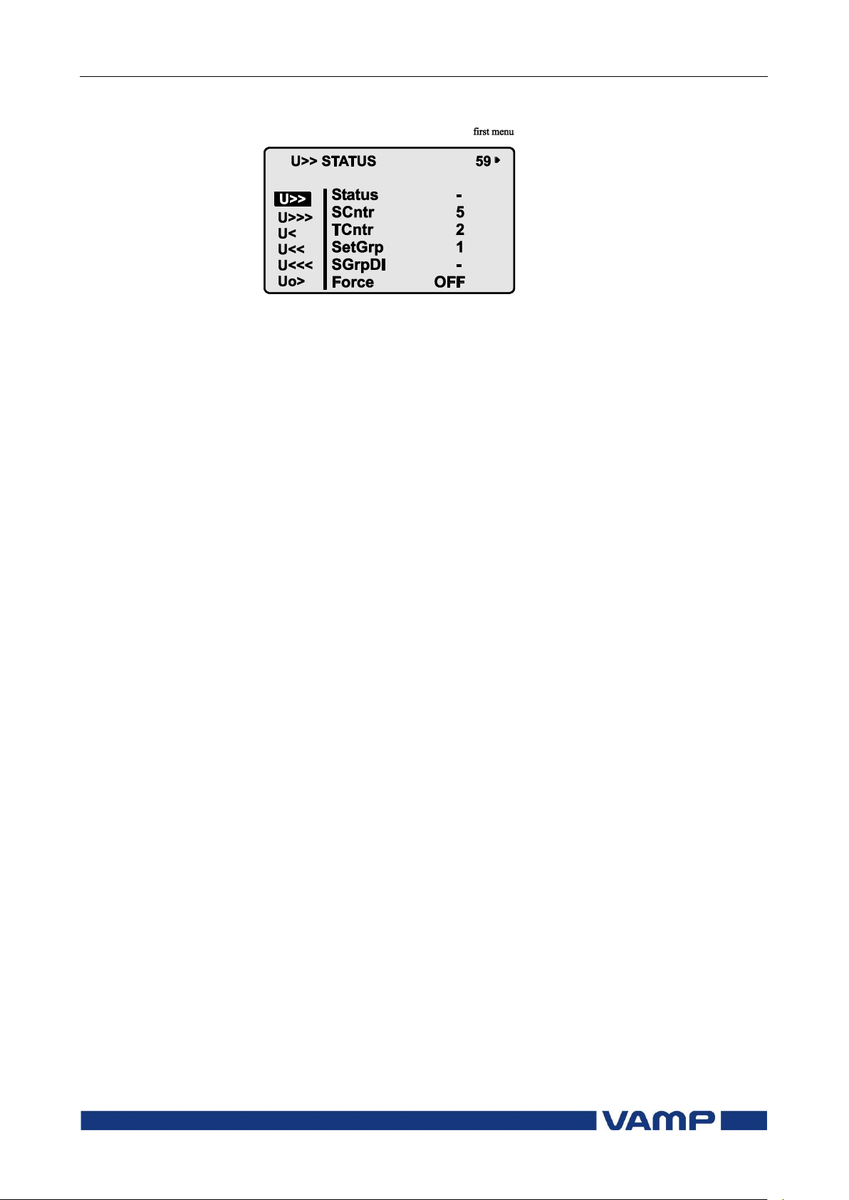
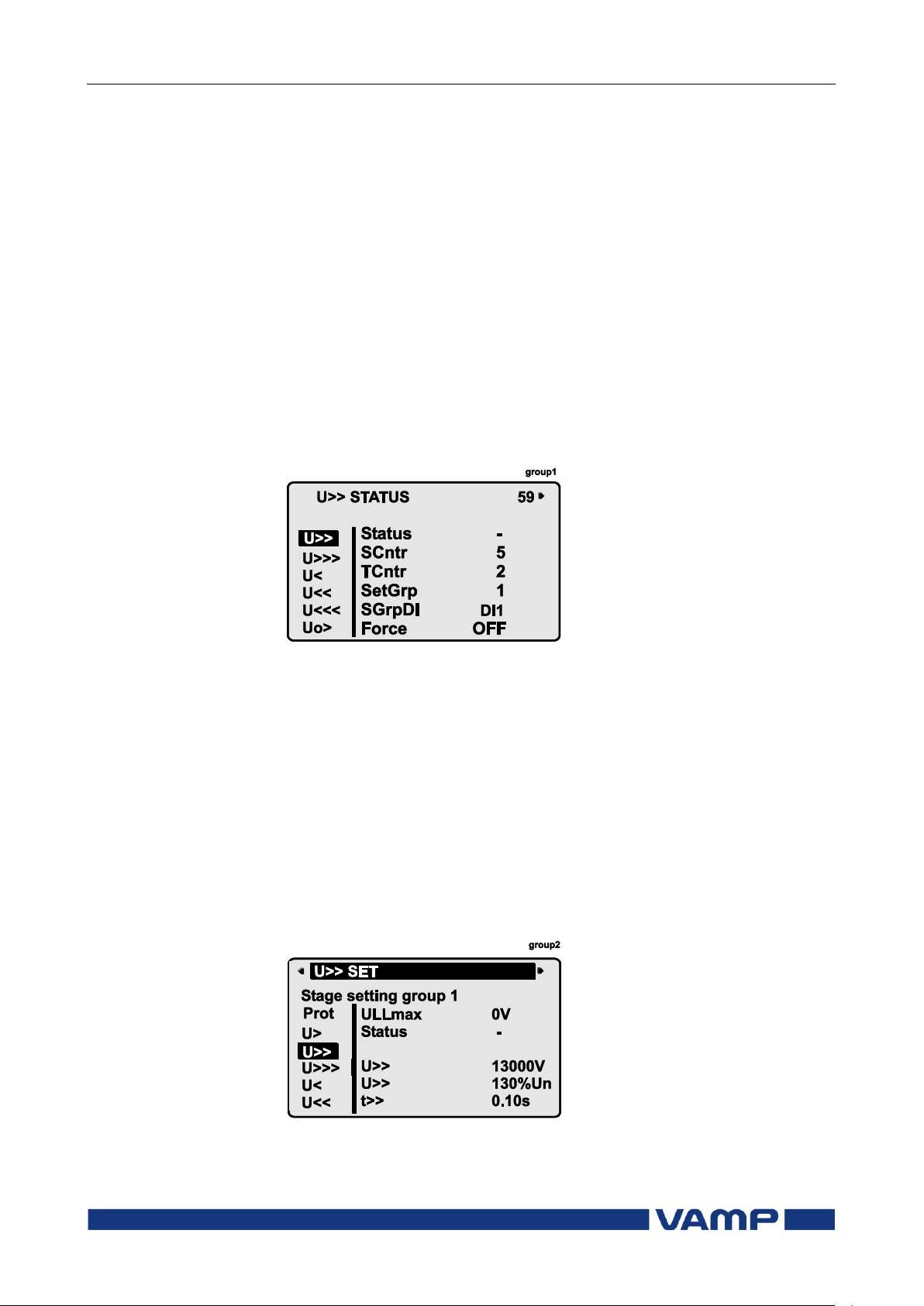
First menu of U>> 59 stage
Figure 2.2.2-1 First menu of U>> 59 stage
This is the status, start and trip counter and setting group
menu. The content is:
Status –
The stage is not detecting any fault at the moment. The
stage can also be forced to pick-up or trip is the operating
level is “Configurator” and the force flag below is on.
Operating levels are explained in chapter 2.2.5
SCntr 5
The stage has picked-up a fault five times since the last
reset or restart. This value can be cleared if the operating
level is at least “Operator”.
TCntr 2
The stage has tripped two times since the last reset or
restart. This value can be cleared if the operating level is at
least “Operator”.
SetGrp 1
The active setting group is one. This value can be edited if
the operating level is at least “Operator”. Setting groups are
explained in chapter 2.2.3.
SGrpDI –
The setting group is not controlled by any digital input. This
value can be edited if the operating level is at least
“Configurator”.
Force Off
The status forcing and output relay forcing is disabled. This
force flag status can be set to “On” or back to “Off” if the
operating level is at least “Configurator”. If no front panel
button is pressed within five minutes and there is no
VAMPSET communication, the force flag will be set to “Off”
position. The forcing is explained in Chapter 2.3.4.
Page 16
2.2 Local panel operations
2 Local panel user interface
Operation and configuration
16
VAMP 24h support phone +358 (0)20 753 3264
VM55.EN005
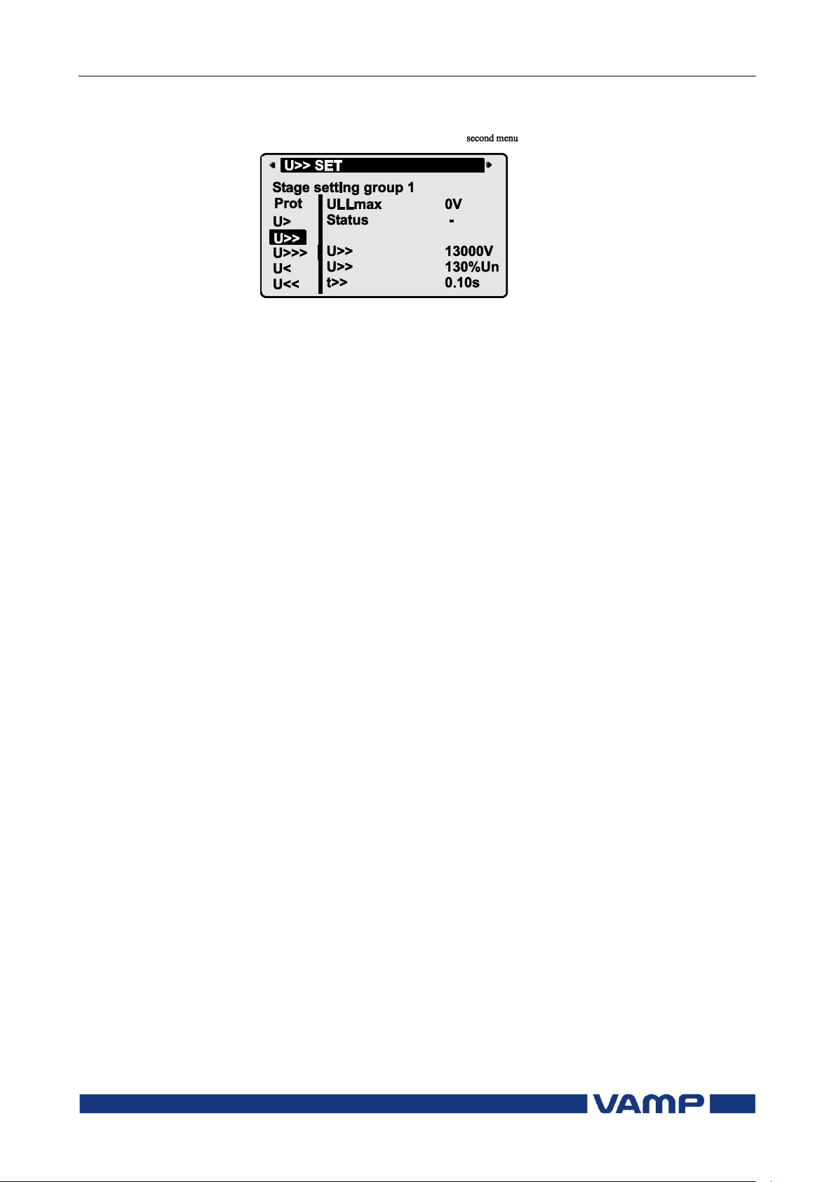
Second menu of U>> 59 stage
Figure 2.2.2-2 Second menu(next on the right) of U> 59 stage
This is the main setting menu. The content is:
Stage setting group 1
These are the group 1 setting values. The other setting
group can be seen by pressing push buttons ENTER and
then RIGHT or LEFT. Setting groups are explained in
chapter 2.2.3.
ILmax 0V
The maximum of three measured voltages is at the moment
0V. This is the value the stage is supervising.
Status –
Status of the stage. This is just a copy of the status value in
the first menu.
U>> 13000 V
The pick-up limit is 13000 V in primary value.
U>> 130%Un
The pick-up limit is 1,3 times the rated voltage. This value
can be edited if the operating level is at least “Operator”.
Operating levels are explained in chapter 2.2.5.
t>> 0.10s
The total operation delay is set to 100 ms. This value can be
edited if the operating level is at least “Operator”.
Page 17
Operation and configuration
2 Local panel user interface
2.2 Local panel operations
VM55.EN005
VAMP 24h support phone +358 (0)20 753 3264
17
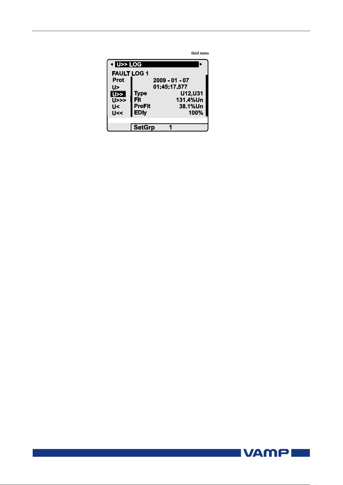
Third menu of U>> 59 stage
Figure 2.2.2-3 Third and last menu (next on the right) of U>> 59 stage
This is the menu for registered values by the U>> stage. Fault
logs are explained in chapter 2.2.4.
FAULT LOG 1
This is the latest of the eight available logs. You may move
between the logs by pressing push buttons ENTER and then
RIGHT or LEFT.
2009 – 01 – 07
Date of the log.
01:45:17.577
Time of the log.
Type U12,U31
The overvoltage fault has been detected in phases L12 and
L31
Flt 131.4 %Un
The fault voltage has been 131.4 % of the nominal value.
PreFlt 38.1 %Un
Prefault voltage has been 38.1 % of the nominal value.
EDly 100%
The elapsed operation delay has been 100% of the setting
0.10 s. Any registered elapsed delay less than 100 % means
that the stage has not tripped, because the fault duration
has been shorter that the delay setting.
SetGrp 1
The setting group has been 1. This line can be reached by
pressing ENTER and several times the DOWN button.
Page 18
2.2 Local panel operations
2 Local panel user interface
Operation and configuration
18
VAMP 24h support phone +358 (0)20 753 3264
VM55.EN005
2.2.3. Setting groups
Most of the protection functions of the relay have two setting
groups. These groups are useful for example when the network
topology is changed frequently. The active group can be
changed by a digital input, through remote communication or
locally by using the local panel.
The active setting group of each protection function can be
selected separately. Figure 2.2.3-1 shows an example where the
changing of the U>> setting group is handled with digital input
one (SGrpDI). If the digital input is TRUE, the active setting
group is group two and correspondingly, the active group is
group one, if the digital input is FALSE. If no digital input is
selected (SGrpDI = -), the active group can be selected by
changing the value of the parameter SetGrp.
Figure 2.2.3-1 Example of protection submenu with setting group
parameters
The changing of the setting parameters can be done easily.
When the desired submenu has been found (with the arrow
keys), press the ENTER key to select the submenu. Now the
selected setting group is indicated in the down-left corner of the
display (See Figure 2.2.3.-2). Set1 is setting group one and Set2
is setting group two. When the needed changes, to the selected
setting group, have been done, press the LEFT or the RIGHT
key to select another group (the LEFT key is used when the
active setting group is 2 and the RIGHT key is used when the
active setting group is 1).
Figure 2.2.3-2 Example of U>> setting submenu
Page 19
Operation and configuration
2 Local panel user interface
2.2 Local panel operations
VM55.EN005
VAMP 24h support phone +358 (0)20 753 3264
19
2.2.4. Fault logs
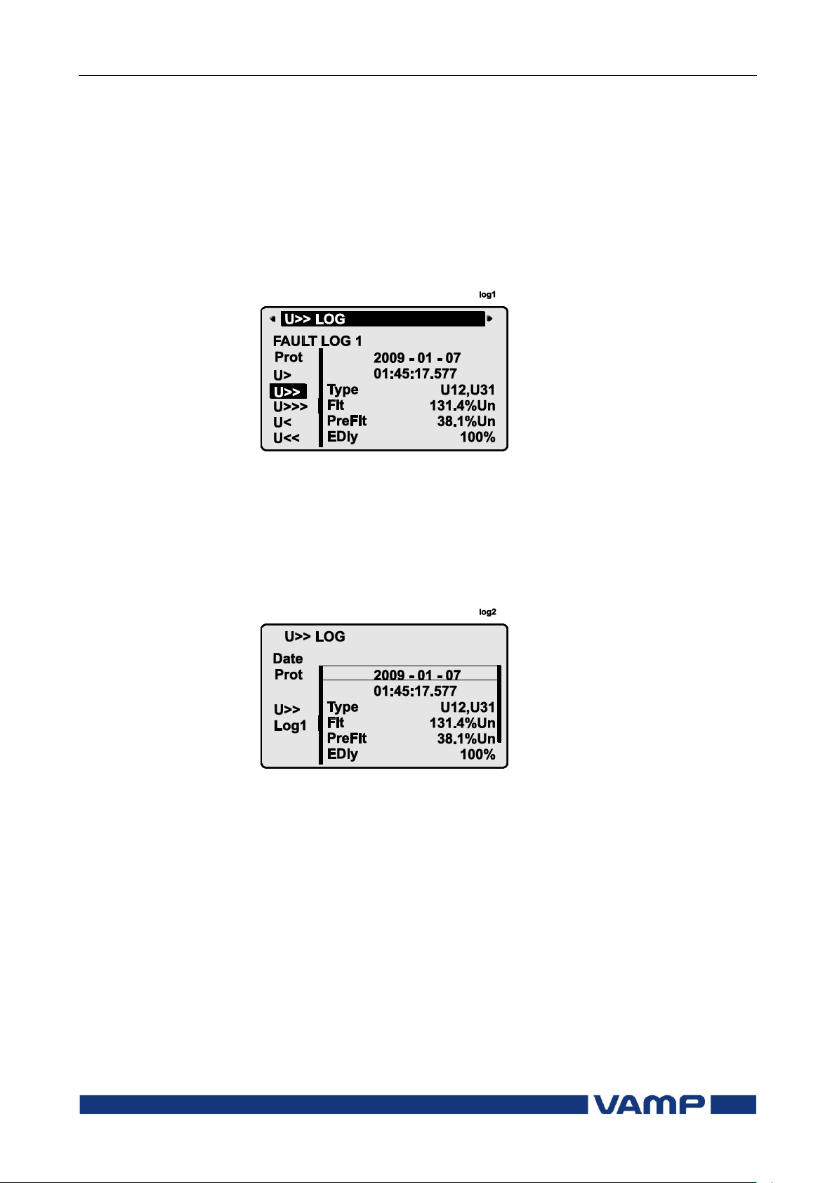
All the protection functions include fault logs. The fault log of a
function can register up to eight different faults with time
stamp information, fault values etc. The fault logs are stored in
non-volatile memory. Each function has its own logs. The fault
logs are not cleared when power is switched off. The user is
able to clear all logs using VAMPSET. Each function has its
own logs (See Figure 2.2.4-1).
Figure 2.2.4-1 Example of fault log
To see the values of, for example, log two, press then ENTER
key to select the current log (log one). The current log number
is then indicated in the down-left corner of the display (See
Figure 2.2.4-2, Log2 = log two). The log two is selected by
pressing the RIGHT key once.
Figure 2.2.4-2 Example of selected fault log
Page 20

2.2 Local panel operations
2 Local panel user interface
Operation and configuration
20
VAMP 24h support phone +358 (0)20 753 3264
VM55.EN005
Use:
Possible to read e.g. parameter values,
measurements and events
Opening:
Level permanently open
Closing:
Closing not possible
Use:
Possible to control objects and to change e.g.
the settings of the protection stages
Opening:
Default password is 1
Setting state:
Push ENTER
Closing:
The level is automatically closed after 10
minutes idle time. Giving the password 9999
can also close the level.
Use:
The configurator level is needed during the
commissioning of the relay. E.g. the scaling of
the voltage and current transformers can be
set.
Opening:
Default password is 2
Setting state:
Push ENTER
Closing:
The level is automatically closed after 10
minutes idle time. Giving the password 9999
can also close the level.
2.2.5. Operating levels
The relay has three operating levels: User level, Operator level
and Configurator level. The purpose of the access levels is to
prevent accidental change of relay configurations, parameters
or settings.
USER level
OPERATOR level
CONFIGURATOR level
Page 21
Operation and configuration
2 Local panel user interface
2.2 Local panel operations
VM55.EN005
VAMP 24h support phone +358 (0)20 753 3264
21
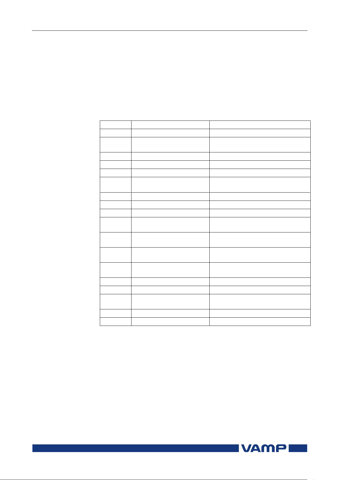
Command
Description
get pwd_break
Get the break code (Example:
6569403)
get serno
Get the serial number of the relay
(Example: 12345)
Command
Description
set pwd_break=4435876
Restore the factory default
passwords (“4435876” is just an
example. The actual code should be
asked from VAMP Ltd.)
Opening access
1. Push the INFO key and the ENTER key on the front panel
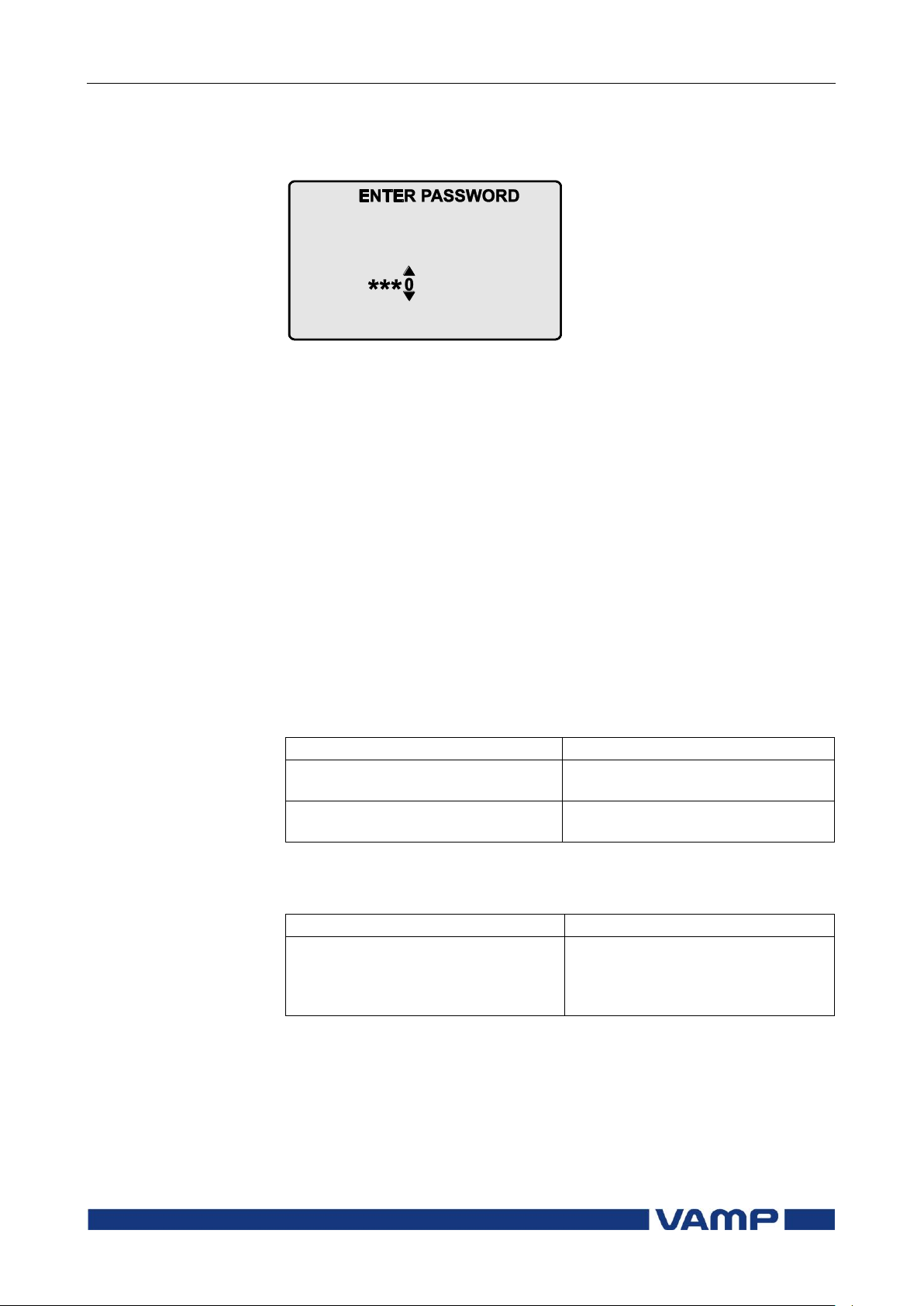
Figure 2.2.5-1 Opening the access level
2. Enter the password needed for the desired level: the
password can contain four digits. The digits are supplied
one by one by first moving to the position of the digit using
the RIGHT key and then setting the desired digit value
using the UP key.
3. Push the ENTER key.
Password handling
The passwords can only be changed using VAMPSET software
connected to the USB -port in front of the relay.
It is possible to restore the password(s) in case the password is
lost or forgotten. In order to restore the password(s), a relay
program is needed. The virtual serial port settings are 38400
bps, 8 data bits, no parity and one stop bit. The bit rate is
configurable via the front panel.
Send both the numbers to [email protected] and ask for a
password break. A device specific break code is sent back to
you. That code will be valid for the next two weeks.
Now the passwords are restored to the default values (See
chapter 2.2.5).
Page 22

2.3 Operating measures
2 Local panel user interface
Operation and configuration
22
VAMP 24h support phone +358 (0)20 753 3264
VM55.EN005
2.3. Operating measures
2.3.1. Control functions
The default display of the local panel is a single-line diagram
including relay identification, Local/Remote indication, Autoreclose on/off selection and selected analogue measurement
values.
Please note that the operator password must be active in order
to be able to control the objects. Please refer to page 21 opening
access.
Toggling Local/Remote control
1. Push the ENTER key. The previously activated object starts
to blink.
2. Select the Local/Remote object (“L” or “R” squared) by using
the arrow keys.
3. Push the ENTER key. The L/R dialog opens. Select
“REMOTE” to enable remote control and disable local
control. Select “LOCAL” to enable local control and disable
remote control.
4. Confirm the setting by pushing the ENTER key. The
Local/Remote state will change.
Object control
Using ENTER and UP / DOWN keys
1. Push the ENTER key. The previously activated object starts
to blink.
2. Select the object to control by using the arrow keys. Please
note that only controllable objects can be selected.
3. Push the ENTER key. A control dialog opens.
4. Select the “Open” or “Close” command by using the UP and
DOWN arrow keys.
5. Confirm the operation by pushing the ENTER key. The
state of the object changes.
Using F1 & F2 in object control mode
1. Push F1 / F2 key. Object assigned to the key starts to blink
and a control dialog opens.
2. Confirm the operation by pushing the ENTER key.
Toggling virtual inputs
1. Push the ENTER key. The previously activated object starts
to blink.
2. Select the virtual input object (empty or black square)
3. The dialog opens
Page 23
Operation and configuration
2 Local panel user interface
2.3 Operating measures
VM55.EN005
VAMP 24h support phone +358 (0)20 753 3264
23
Value
Menu/Submenu
Description
f
U/FREQ
Frequency [Hz]
Uline
U/LINE VOLTAGES
Average value for the three line
voltages [V]
U12
U/LINE VOLTAGES
Phase-to-phase voltage U12 [V]
U23
U/LINE VOLTAGES
Phase-to-phase voltage U23 [V]
U31
U/LINE VOLTAGES
Phase-to-phase voltage U31 [V]
UL
U/PHASE VOLTAGES
Average for the three phase voltages
[V]
UL1
U/PHASE VOLTAGES
Phase-to-earth voltage UL1 [V]
UL2
U/PHASE VOLTAGES
Phase-to-earth voltage UL2 [V]
UL3
U/PHASE VOLTAGES
Phase-to-earth voltage UL3 [V]
Uo
U/SYMMETRIC
VOLTAGES
Residual voltage Uo [%]
U1
U/SYMMETRIC
VOLTAGES
Positive sequence voltage [%]
U2
U/SYMMETRIC
VOLTAGES
Negative sequence voltage [%]
U2/U1
U/SYMMETRIC
VOLTAGES
Negative sequence voltage related to
positive sequence voltage [%]
Count
U/VOLT. INTERRUPTS
Voltage interrupts counter [ ]
Prev
U/VOLT. INTERRUPTS
Previous interruption [ ]
Total
U/VOLT. INTERRUPTS
Total duration of voltage
interruptions [days, hours]
Prev
U/VOLT. INTERRUPTS
Duration of previous interruption [s]
Status
U/VOLT. INTERRUPTS
Voltage status [LOW; NORMAL]
4. Select “VIon” to activate the virtual input or select “VIoff” to
deactivate the virtual input
2.3.2. Measured data
The measured values can be read from the Meas menu and its
submenus. Furthermore, any measurement value in the
following table can be displayed on the main view next to the
single line diagram. Up to six measurements can be shown.
Page 24
2.3 Operating measures
2 Local panel user interface
Operation and configuration
24
VAMP 24h support phone +358 (0)20 753 3264
VM55.EN005
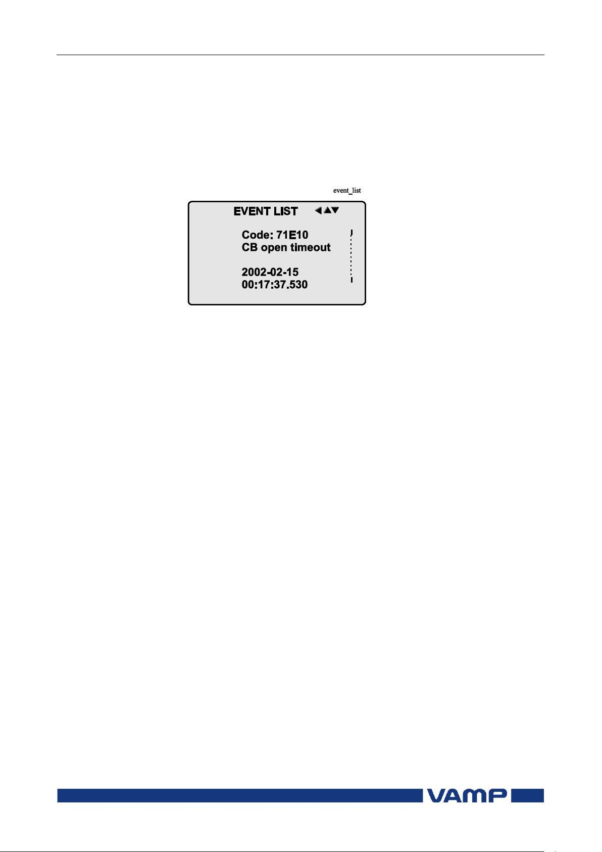
2.3.3. Reading event register
The event register can be read from the Evnt submenu:
1. Push the RIGHT key once.
2. The EVENT LIST appears. The display contains a list of all
the events that have been configured to be included in the
event register.
Figure 2.3.3-1. Example of an event register
3. Scroll through the event list with the UP and DOWN keys.
4. Exit the event list by pushing the LEFT key.
It is possible to set the order in which the events are sorted. If
the “Order” -parameter is set to “New-Old”, then the first event
in the EVENT LIST is the most recent event.
Page 25
Operation and configuration
2 Local panel user interface
2.3 Operating measures
VM55.EN005
VAMP 24h support phone +358 (0)20 753 3264
25
2.3.4. Forced control (Force)
In some menus it is possible to switch a function on and off by
using a force function. This feature can be used, for instance,
for testing a certain function. The force function can be
activated as follows:
1. Move to the setting state of the desired function, for
example DO (see chapter 2.4, on page 26).
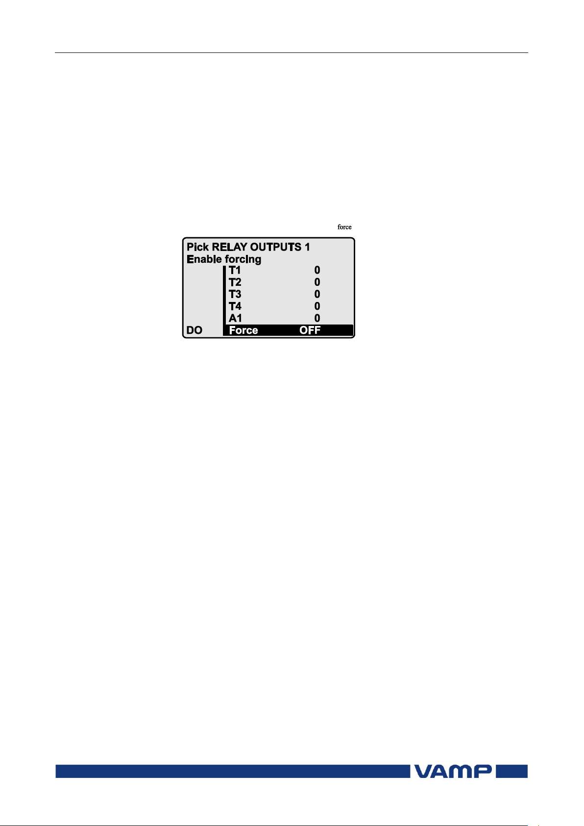
2. Select the Force function (the background color of the force
text is black).
Figure 2.3.4-1 Selecting Force function
3. Push the ENTER key.
4. Push the UP or DOWN key to change the "OFF" text to
"ON", that is, to activate the Force function.
5. Push the ENTER key to return to the selection list. Choose
the signal to be controlled by force with the UP and DOWN
keys, for instance the T1 signal.
6. Push the ENTER key to confirm the selection. Signal T1
can now be controlled by force.
7. Push the UP or DOWN key to change the selection from "0"
(not alert) to "1" (alert) or vice versa.
8. Push the ENTER key to execute the forced control operation
of the selected function, e.g., making the output relay of T1
to pick up.
9. Repeat the steps 7 and 8 to alternate between the on and off
state of the function.
10. Repeat the steps 1...4 to exit the Force function.
11. Push the CANCEL key to return to the main menu.
NOTE! All the interlockings and blockings are bypassed when the force control
is used.
Page 26
2.4 Configuration and parameter
setting
2 Local panel user interface
Operation and configuration
26
VAMP 24h support phone +358 (0)20 753 3264
VM55.EN005
2.4. Configuration and parameter setting
The minimum procedure to configure a relay is
1. Open the access level "Configurator". The default password
for configurator access level is 2.
2. Set the rated values in menu [CONF] including at least
current transformers, voltage transformers and generator
ratings. Also the date and time settings are in this same
main menu.
3. Enable the needed protection functions and disable the rest
of the protection functions in main menu [Prot].
4. Set the setting parameter of the enable protection stages
according the application.
5. Connect the output relays to the start and trip signals of the
enabled protection stages using the output matrix. This can
be done in main menu [DO], although the VAMPSET
program is recommended for output matrix editing.
6. Configure the needed digital inputs in main menu [DI].
7. Configure blocking and interlockings for protection stages
using the block matrix. This can be done in main menu
[Prot], although VAMPSET is recommended for block
matrix editing.
Some of the parameters can only be changed via the USB-port
using the VAMPSET software. Such parameters, (for example
passwords, blockings and mimic configuration) are normally set
only during commissioning.
Some of the parameters require the restarting of the relay. This
restarting is done automatically when necessary. If a
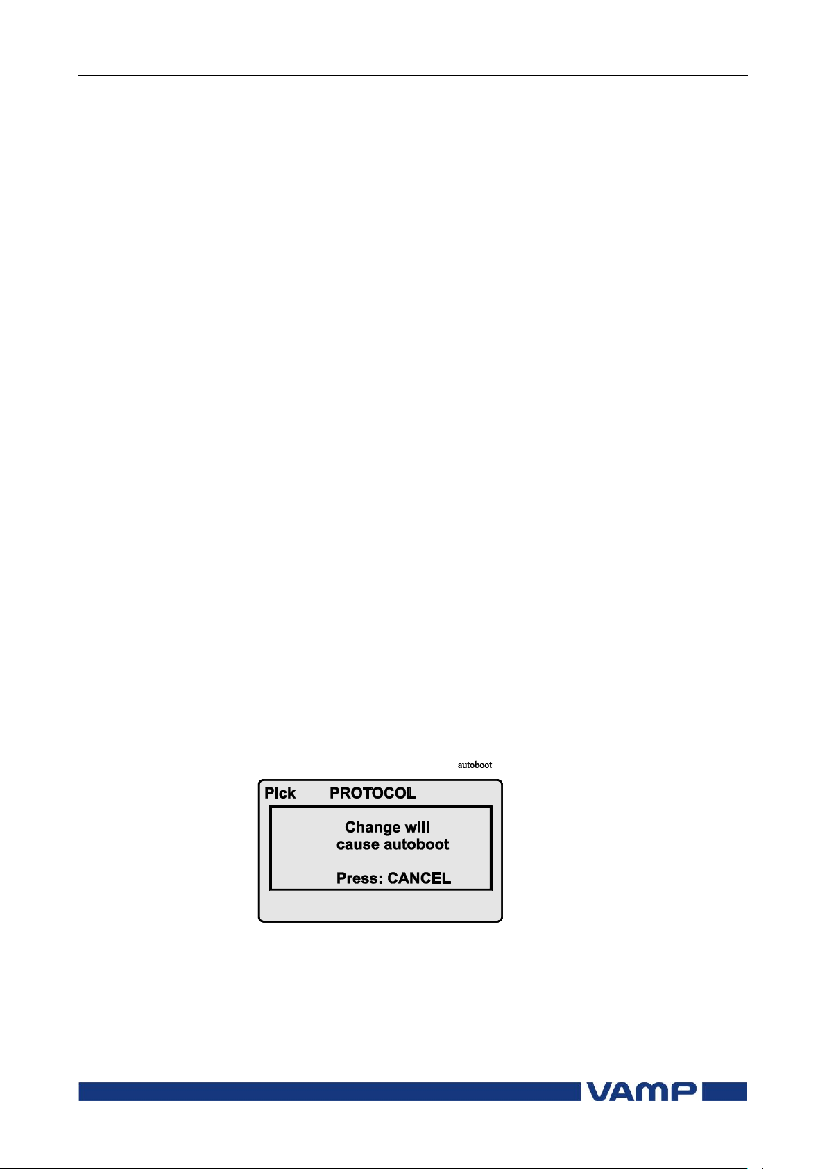
parameter change requires restarting, the display will show as
Figure 2.4-1.
Figure 2.4-1 Example of auto-reset display
Press CANCEL to return to the setting view. If a parameter
must be changed, press the ENTER key again. The parameter
can now be set. When the parameter change is confirmed with
the ENTER key, a [RESTART]- text appears to the top-right
corner of the display. This means that auto-resetting is
Page 27
Operation and configuration
2 Local panel user interface
2.4 Configuration and parameter
setting
VM55.EN005
VAMP 24h support phone +358 (0)20 753 3264
27
pending. If no key is pressed, the auto-reset will be executed
within few seconds.
2.4.1. Parameter setting
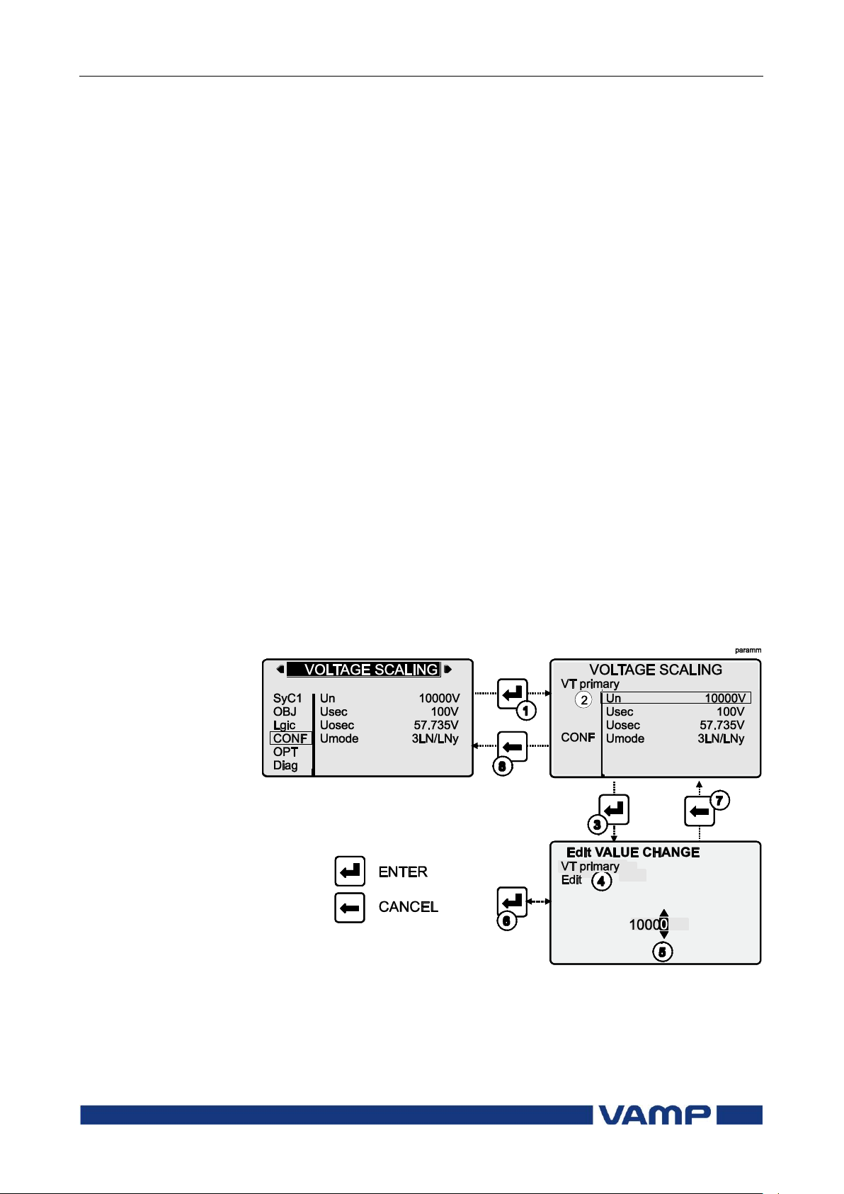
1. Move to the setting state of the desired menu (for example
CONF/VOLTAGE SCALING) by pushing the ENTER key.
The Pick text appears in the upper-left part of the display.
2. Enter the password associated with the configuration level
by pushing the INFO key and then using the arrow keys
and the ENTER key (default value is 0002). For more
information about the access levels, please refer to Chapter
2.2.5.
3. Scroll through the parameters using the UP and DOWN
keys. A parameter can be set if the background color of the
line is black. If the parameter cannot be set the parameter
is framed.
4. Select the desired parameter (for example Un) with the
ENTER key.
5. Use the UP and DOWN keys to change a parameter value.
If the value contains more than one digit, use the LEFT and
RIGHT keys to shift from digit to digit, and the UP and
DOWN keys to change the digits.
6. Push the ENTER key to accept a new value. If you want to
leave the parameter value unchanged, exit the edit state by
pushing the CANCEL key.
Figure 2.4.1-1.Changing parameters
Page 28
2.4 Configuration and parameter
setting
2 Local panel user interface
Operation and configuration
28
VAMP 24h support phone +358 (0)20 753 3264
VM55.EN005
2.4.2. Setting range limits
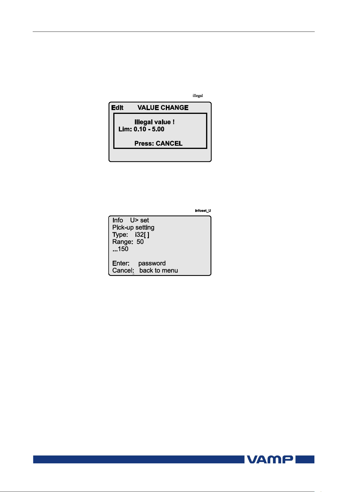
If the given parameter setting values are out-of-range values, a
fault message will be shown when the setting is confirmed with
the ENTER key. Adjust the setting to be within the allowed
range.
Figure 2.4.2-1 Example of a fault message
The allowed setting range is shown in the display in the setting
mode. To view the range, push the INFO key. Push the
CANCEL key to return to the setting mode.
Figure 2.4.2-2 Allowed setting ranges show in the display
2.4.3. Disturbance recorder menu DR
Via the submenus of the disturbance recorder menu the
following functions and features can be read and set:
DISTURBANCE RECORDER
Recording mode (Mode)
Sample rate (SR)
Recording time (Time)
Pre trig time (PreTrig)
Manual trigger (ManTrig)
Count of ready records (ReadyRec)
REC. CHANNELS
Add a link to the recorder (AddCh)
Clear all links (ClrCh)
Page 29

Operation and configuration
2 Local panel user interface
2.4 Configuration and parameter
setting
VM55.EN005
VAMP 24h support phone +358 (0)20 753 3264
29
Available links:
DO, DI
Uline, Uphase
U2/U1, U2, U1
f
Uo
UL3, UL2, UL1
U31, U23, U12
fy, U12y
2.4.4. Configuring digital inputs DI
The following functions can be read and set via the submenus
of the digital inputs menu:
The status of digital inputs (DIGITAL INPUTS 1,2)
Operation counters (DI COUNTERS)
Operation delay (DELAYs for DigIn)
The polarity of the input signal (INPUT POLARITY). Either
normally open (NO) or normally closed (NC) circuit.
Event enabling EVENT MASK1
2.4.5. Configuring digital outputs DO
The following functions can be read and set via the submenus
of the digital outputs menu:
The status of the output relays (RELAY OUTPUTS1 and 2)
The forcing of the output relays (RELAY OUTPUTS1 and 2)
(only if Force = ON):
o Forced control (0 or 1) of the Trip relays
o Forced control (0 or 1) of the Alarm relays
o Forced control (0 or 1) of the IF relay
The configuration of the output signals to the output relays.
The configuration of the operation indicators (LED) Alarm
and Trip and application specific alarm leds A, B, C, D, E, F,
G and H (that is, the output relay matrix).
NOTE! The amount of Trip and Alarm relays depends on the relay type and
optional hardware.
Page 30

2.4 Configuration and parameter
setting
2 Local panel user interface
Operation and configuration
30
VAMP 24h support phone +358 (0)20 753 3264
VM55.EN005
2.4.6. Configuring analogue outputs AO (Option)
Via the submenus of the analogue output menu the following
functions can be read and set:
ANALOG OUTPUT
Value of AO1 (AO1)
Forced control of analogue output (Force)
ANALOG OUTPUT
Value linked to the analogue output (Lnk1)
(See list available links)
Scaled minimum of linked value (Min)
Scaled maximum of linked value (Max)
Scaled minimum of analogue output (AOmin)
Scaled maximum of analogue output (AOmax)
Value of analogue output (AO1)
Available links:
f
U12, U23, U31
UL1, UL2, UL3
Uline, Uphase
PrgVal
Uo
2.4.7. Protection menu Prot
The following functions can be read and set via the submenus
of the Prot menu:
Reset all the counters (PROTECTION SET/ClAll)
Read the status of all the protection functions (PROTECT
STATUS 1-x)
Enable and disable protection functions (ENABLED
STAGES 1-x)
Define the interlockings using block matrix (only with
VAMPSET).
Each stage of the protection functions can be disabled or
enabled individually in the Prot menu. When a stage is
enabled, it will be in operation immediately without a need to
reset the relay.
The relay includes several protection functions. However, the
processor capacity limits the number of protection functions
that can be active at the same time.
Page 31

Operation and configuration
2 Local panel user interface
2.4 Configuration and parameter
setting
VM55.EN005
VAMP 24h support phone +358 (0)20 753 3264
31
2.4.8. Configuration menu CONF
The following functions and features can be read and set via
the submenus of the configuration menu:
DEVICE SETUP
Bit rate for the command line interface in communication
ports and the USB-port in the front panel. The front panel
is always using this setting. If SPABUS is selected for the
rear panel port, the bit rate is according SPABUS settings.
Access level [Acc]
LANGUAGE
List of available languages in the relay
VOLTAGE SCALING
Rated VT primary voltage (Uprim)
Rated VT secondary voltage (Usec)
Rated U
Voltage measuring mode (Umode)
VT secondary voltage (Uosec)
0
UNITS FOR MIMIC DISPLAY
Unit for voltages (V). The choices are V (volt) or kV
(kilovolt).
DEVICE INFO
Relay type (Type VAMP 55)
Serial number (SerN)
Software version (PrgVer)
Bootcode version (BootVer)
DATE/TIME SETUP
Day, month and year (Date)
Time of day (Time)
Date format (Style). The choices are "yyyy-mm-dd",
"dd.nn.yyyy" and "mm/dd/yyyy".
CLOCK SYNCHRONISATION
Digital input for minute sync pulse (SyncDI). If any digital
input is not used for synchronization, select "".
Daylight saving time for NTP synchronization (DST).
Detected source of synchronization (SyScr).
Synchronization message counter (MsgCnt).
Latest synchronization deviation (Dev).
Page 32

2.4 Configuration and parameter
setting
2 Local panel user interface
Operation and configuration
32
VAMP 24h support phone +358 (0)20 753 3264
VM55.EN005
The following parameters are visible only when the access level
is higher than "User".
Offset, i.e. constant error, of the synchronization source
(SyOS).
Auto adjust interval (AAIntv).
Average drift direction (AvDrft): "Lead" or "lag".
Average synchronization deviation (FilDev).
2.4.9. Protocol menu Bus
There are three optional communication ports in the rear
panel. The availability depends on the communication options
(see chapter Ordering code in the technical description). In
addition there is a USB-connector in the front panel overruling
the local port in the rear panel.
REMOTE PORT
Communication protocol for remote port [Protocol].
Message counter [Msg#]. This can be used to verify that the
device is receiving messages.
Communication error counter [Errors].
Communication time-out error counter [Tout].
Information of bit rate/data bits/parity/stop bits.
This value is not directly editable. Editing is done in the
appropriate protocol setting menus.
The counters are useful when testing the communication.
PC (LOCAL/SPA BUS)
This is a second menu for local port. The VAMPSET
communication status is showed.
Bytes/size of the transmitter buffer [Tx].
Message counter [Msg#]. This can be used to verify that the
device is receiving messages.
Communication error counter [Errors]
Communication time-out error counter [Tout].
Same information as in the previous menu.
EXTENSION PORT
Communication protocol for extension port [Protocol].
Message counter [Msg#]. This can be used to verify that the
device is receiving messages.
Communication error counter [Errors].
Communication time-out error counter [Tout].
Information of bit rate/data bits/parity/stop bits.
This value is not directly editable. Editing is done in the
appropriate protocol setting menus.
Page 33

Operation and configuration
2 Local panel user interface
2.4 Configuration and parameter
setting
VM55.EN005
VAMP 24h support phone +358 (0)20 753 3264
33
Ethernet
These parameters are used by the ethernet interface module.
For changing the nnn.nnn.nnn.nnn style parameter values,
VAMPSET is recommended.
Ethernet port protocol [Protoc].
IP Port for protocol [Port]
IP address [IpAddr].
Net mask [NetMsk].
Gateway [Gatew].
Name server [NameSw].
Network time protocol (NTP) server [NTPSvr].
TCP Keep alive interval [KeepAlive]
MAC address [MAC]
IP Port for Vampset [VS Port]
Message counter [Msg#]
Error counter [Errors]
Timeout counter [Tout]
MODBUS
Modbus address for this slave device [Addr]. This address
has to be unique within the system.
Modbus bit rate [bit/s]. Default is "9600".
Parity [Parity]. Default is "Even".
For details see the technical description part of the manual.
EXTERNAL I/O protocol
External I/O is actually a set of protocols which are designed to
be used with the extension I/O modules connected to the
extension port. Only one instance of this protocol is possible.
Selectable protocols:
Modbus: This is a modbus master protocol.
Bit rate [bit/s]. Default is ”9600”.
Parity [Parity]. Default is ”Even”.
RTDInput: This protocol is designed to be used together
with VIO 12A RTD input module.
Bit rate [bit/s]. Default is ”9600”.
Parity [Parity]. Default is ”Even”.
For details see the technical desctiption part of the manual.
SPA BUS
Several instances of this protocol are possible.
SPABUS address for this device [Addr]. This address has to
be unique within the system.
Bit rate [bit/s]. Default is "9600".
Event numbering style [Emode]. Default is "Channel".
For details see the technical description part of the manual.
Page 34

2.4 Configuration and parameter
setting
2 Local panel user interface
Operation and configuration
34
VAMP 24h support phone +358 (0)20 753 3264
VM55.EN005
IEC 60870-5-103
Only one instance of this protocol is possible.
Address for this device [Addr]. This address has to be
unique within the system.
Bit rate [bit/s]. Default is "9600".
Minimum measurement response interval [MeasInt].
ASDU6 response time mode [SyncRe].
For details see the technical description part of the manual.
IEC 103 DISTURBANCE RECORDINGS
For details see the technical description part of the manual.
PROFIBUS
Only one instance of this protocol is possible.
[Mode]
Bit rate [bit/s]. Use 2400 bps. This parameter is the bit rate
between the main CPU and the Profibus ASIC. The actual
Profibus bit rate is automatically set by the Profibus master
and can be up to 12 Mbit/s.
Event numbering style [Emode].
Size of the Profibus Tx buffer [InBuf].
Size of the Profibus Rx buffer [OutBuf].
When configuring the Profibus master system, the length of
these buffers are needed. The size of the both buffers is set
indirectly when configuring the data items for Profibus.
Address for this slave device [Addr]. This address has to be
unique within the system.
Profibus converter type [Conv]. If the shown type is a dash
“-“, either Profibus protocol has not been selected or the
device has not restarted after protocol change or there is a
communication problem between the main CPU and the
Profibus ASIC.
For details see the technical description part of the manual.
DNP3
Only one instance of this protocol is possible.
Bit rate [bit/s]. Default is "9600".
[Parity].
Address for this device [SlvAddr]. This address has to be
unique within the system.
Master's address [MstrAddr].
For further details see the technical description part of the
manual.
Page 35
Operation and configuration
2 Local panel user interface
2.4 Configuration and parameter
setting
VM55.EN005
VAMP 24h support phone +358 (0)20 753 3264
35
IEC 60870-5-101
Bit rate [bit/s]. Default is “9600”.
[Parity].
Link layer address for this device [LLAddr].
ASDU address [ALAddr].
For further details see the technical description part of the
manual.
2.4.10. Single line diagram editing
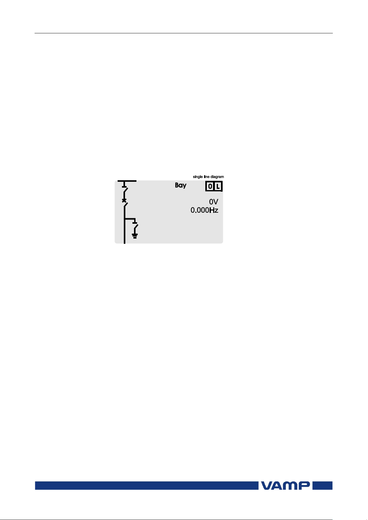
The single-line diagram is drawn with the VAMPSET software.
For more information, please refer to the VAMPSET manual
(VMV.EN0xx).
Figure 2.4.10-1 Single line diagram
2.4.11. Blocking and interlocking configuration
The configuration of the blockings and interlockings is done
with the VAMPSET software. Any start or trip signal can be
used for blocking the operation of any protection stage.
Furthermore, the interlocking between objects can be
configured in the same blocking matrix of the VAMPSET
software. For more information, please refer to the VAMPSET
manual (VMV.EN0xx).
Page 36

3 VAMPSET PC software
Operation and configuration
36
VAMP 24h support phone +358 (0)20 753 3264
VM55.EN005
3. VAMPSET PC software
The PC user interface can be used for:
On-site parameterization of the relay
Loading relay software from a computer
Reading measured values, registered values and events to a
computer.
Continuous monitoring of all values and events.
A USB port is available for connecting a local PC with
VAMPSET to the relay. A standard USB-B cable can be used.
The VAMPSET program can also use the TCP/IP LAN
connection. Optional hardware is required for Ethernet
connection.
There is a free of charge PC program called VAMPSET
available for configuration and setting of VAMP relays. Please
download the latest VAMPSET.exe from our web page
www.vamp.fi. For more information about the VAMPSET
software, please refer to the user’s manual with the code
VMV.EN0xx. Also the VAMPSET user’s manual is available at
our web site.
When the relay is connected to a PC with a USB, a virtual
comport will be created. The comport number may vary
depending on your computer hardware. In order to check the
correct port number, please go to Windows Device Manager:
Control Panel->System->Hardware->Device Manager and
under Ports(COM&LPT) for “USB Serial Port”. The correct
comport must be selected from the VAMPSET menu: Settings>Communication Settings. Speed setting can be set up to
187500 bps. Default setting in the relay is 38400 bps which can
be manually changed from the front panel of the device.
By default every new relay will create a new comport. To avoid
this behavior, the user needs to add a REG_BINARY value
called IgnoreHWSerNum04036001 to the Windows registry and
set it to 01. The location for this value is
HKEY_LOCAL_MACHINE\SYSTEM\CurrentControlSet\Con
trol\UsbFlags\.
Page 37

Technical description Table of Contents
VM55.EN005
VAMP 24h support phone +358 (0)20 753 3264
37
Table of Contents
1. Introduction .......................................................................... 40
1.1. Main features ................................................................... 40
1.2. Principles of numerical protection techniques .......... 41
2. Protection functions ............................................................. 44
2.1. Maximum number of protection stages in one
application ................................................................................ 44
2.2. General features of protection stages ........................ 44
2.3. List of protection functions ............................................. 49
2.4. Overvoltage protection U> (59) ................................... 50
2.5. Volts/hertz over-excitation protection Uf> (24)........... 53
2.6. Undervoltage protection U1< (27P) .............................. 56
2.7. Undervoltage protection U< (27) ................................. 60
2.8. Zero sequence voltage protection U0> (59N) ............ 63
2.9. Overfrequency and underfrequency Protection f>, f<
(81H/81L) ................................................................................... 66
2.10. Synchrocheck (25) .......................................................... 69
2.11. Circuit breaker failure protection CBFP (50BF) ........... 76
2.12. Programmable stages (99) ............................................ 78
3. Supporting functions ............................................................ 82
3.1. Event log ........................................................................... 82
3.2. Disturbance recorder ..................................................... 84
3.3. Voltage sags and swells ................................................. 88
3.4. Voltage interruptions ...................................................... 90
3.5. Voltage transformer supervision ................................... 92
3.6. System clock and synchronization ............................... 93
3.7. Self-supervision ................................................................. 97
3.7.1. Diagnostics .............................................................. 97
4. Measurement functions ....................................................... 99
4.1. Measurement accuracy ................................................ 99
4.2. Minimum and maximum values.................................. 100
4.3. Voltage measurement modes .................................... 100
4.4. Symmetric components ............................................... 101
4.5. Primary, secondary and per unit scaling................... 105
4.5.1. Voltage scaling ..................................................... 105
4.6. Analogue output (option) ........................................... 108
4.6.1. mA scaling example ............................................ 108
5. Control functions ................................................................ 109
5.1. Output relays ................................................................. 109
5.2. Digital inputs ................................................................... 110
5.3. Virtual inputs and outputs ............................................ 112
5.4. Function keys / F1 & F2 ................................................. 113
5.5. Output matrix ................................................................. 114
5.6. Blocking matrix .............................................................. 115
Page 38

Table of Contents
Technical description
38
VAMP 24h support phone +358 (0)20 753 3264
VM55.EN005
5.7. Controllable objects ..................................................... 116
5.7.1. Local/Remote selection ...................................... 118
5.8. Logic functions .............................................................. 119
6. Communication ................................................................. 120
6.1. Communication ports .................................................. 120
6.1.1. Local port (Front panel) ....................................... 121
6.1.2. Remote port .......................................................... 123
6.1.3. Extension port ........................................................ 124
6.1.4. Ethernet port .......................................................... 125
6.2. Communication protocols .......................................... 126
6.2.1. PC communication .............................................. 126
6.2.2. Modbus TCP and Modbus RTU ........................... 127
6.2.3. Profibus DP ............................................................. 128
6.2.4. SPA-bus ................................................................... 130
6.2.5. IEC 60870-5-103 ..................................................... 131
6.2.6. DNP 3.0 ................................................................... 133
6.2.7. IEC 60870-5-101 ..................................................... 134
6.2.8. External I/O (Modbus RTU master) ..................... 135
6.2.9. IEC 61850 ................................................................ 135
6.2.10. EtherNet/IP ............................................................. 137
7. Application ......................................................................... 139
7.1. Trip circuit supervision ................................................... 139
7.1.1. Trip circuit supervision with one digital input .... 140
7.1.2. Trip circuit supervision with two digital inputs ... 145
8. Connections ....................................................................... 149
8.1. Rear panel view ............................................................ 149
8.2. Auxiliary voltage ............................................................ 151
8.3. Output relays ................................................................. 151
8.4. Serial communication connection............................. 151
8.4.1. Pin assignments of communication options ..... 152
8.4.2. Front panel connector ......................................... 154
8.5. Optional digital input/output card ............................ 155
8.6. External option modules .............................................. 158
8.6.1. External input / output module .......................... 158
8.7. Connection examples .................................................. 164
9. Technical data ................................................................... 167
9.1. Connections................................................................... 167
9.1.1. Measuring circuitry ............................................... 167
9.1.2. Auxiliary voltage ................................................... 167
9.1.3. Digital inputs .......................................................... 167
9.1.4. Trip contacts .......................................................... 168
9.1.5. Alarm contacts ..................................................... 168
9.1.6. Local serial communication port ....................... 168
9.1.7. Remote control connection (option) ................ 168
9.1.8. Analogue output connection (option) ............. 169
Page 39

Technical description
Table of Contents
VM55.EN005
VAMP 24h support phone +358 (0)20 753 3264
39
9.2. Tests and environmental conditions .......................... 169
9.2.1. Disturbance tests .................................................. 169
9.2.2. Test voltages .......................................................... 169
9.2.3. Mechanical tests .................................................. 169
9.2.4. Environmental conditions .................................... 169
9.2.5. Casing .................................................................... 170
9.2.6. Package................................................................. 170
9.3. Protection stages .......................................................... 170
9.3.1. Voltage protection ............................................... 170
9.3.2. Frequency protection .......................................... 172
9.3.3. Synchrocheck function ........................................ 173
9.3.4. Circuit-breaker failure protection ...................... 173
9.3.5. Digital input / output card (option) ................... 174
9.4. Supporting functions ..................................................... 174
9.4.1. Disturbance recorder (DR) .................................. 174
9.4.2. Voltage sag & swell .............................................. 175
9.4.3. Voltage interruptions ............................................ 175
10. Abbreviations and symbols .............................................. 176
11. Construction ....................................................................... 178
12. Order information ............................................................... 180
13. Revision history ................................................................... 182
14. Reference information ....................................................... 183
Page 40

1.1 Main features
1 Introduction
Technical description
40
VAMP 24h support phone +358 (0)20 753 3264
VM55.EN005
1. Introduction
This part of the user manual describes the protection functions,
provides application examples and contains technical data of
the functions.
The numerical device includes basic voltage and frequency
protection functions needed in common applications. Further,
the device includes several programmable functions, such as
trip circuit supervision and check of synchronism and also
communication protocols for various protection and
communication applications.
1.1. Main features
Fully digital signal handling with microprocessor
technology, and high measuring accuracy on all the setting
ranges due to an accurate A/D conversion technique.
Set of functions for voltage and frequency based protection
of lines, generators and transformers
The device can be matched to the requirements of the
application by disabling the functions that are not needed.
Flexible control and blocking possibilities due to digital
signal control inputs (DI) and outputs (DO).
Easy adaptability of the device to various substations and
alarm systems due to flexible signal-grouping matrix in the
device.
Possibility to control objects (e.g. circuit-breakers,
disconnectors) from relay HMI or SCADA/automation
system
Freely configurable large display with six measurement
values.
Freely configurable interlocking schemes with basic logic
functions.
Recording of events and fault values into an event register
from which the data can be read via relay HMI or by means
of a PC based VAMPSET user interface.
All events, indications, parameters and waveforms are in
non-volatile memory.
Easy configuration, parameterisation and reading of
information via local HMI, or with a VAMPSET user
interface.
Easy connection to various automation systems due to
several available communication protocols. Native
IEC61850 implementation is available as option.
Page 41

Technical description
1 Introduction
1.2 Principles of numerical
protection techniques
VM55.EN005
VAMP 24h support phone +358 (0)20 753 3264
41
Flexible communication option concept available to support
different media requirements (serial interfaces, optical
fibres, Ethernet etc),
Built-in, self-regulating ac/dc converter for auxiliary power
supply from any source within the range from 40 to 265 Vdc
or Vac. The alternative power supply is for 18 to 36 Vdc.
Built-in disturbance recorder for evaluating all the analogue
and digital signals.
1.2. Principles of numerical protection
techniques
The device is fully designed using numerical technology. This
means that all the signal filtering, protection and control
functions are implemented through digital processing.
The numerical technique used in the device is primarily based
on an adapted Fast Fourier Transformation (FFT). In FFT the
number of calculations (multiplications and additions), which
are required to filter out the measuring quantities, remains
reasonable.
By using synchronized sampling of the measured analog
signals and a sample rate according to the 2n series, the FFT
technique leads to a solution, which can be realized with a 16
bit micro controller, without using a separate DSP (Digital
Signal Processor).
The synchronized sampling means an even number of 2n
samples per period (e.g. 32 samples per a period). This means
that the frequency must be measured and the number of the
samples per period must be controlled accordingly so that the
number of the samples per period remains constant if the
frequency changes. VAMP relays have built-in automatical
frequency tracking and as an alternative the system frequency
can be set manually.
Apart from the FFT calculations, some protection functions also
require the symmetrical components to be calculated for
obtaining the positive, negative and zero phase sequence
components of the measured quantity.
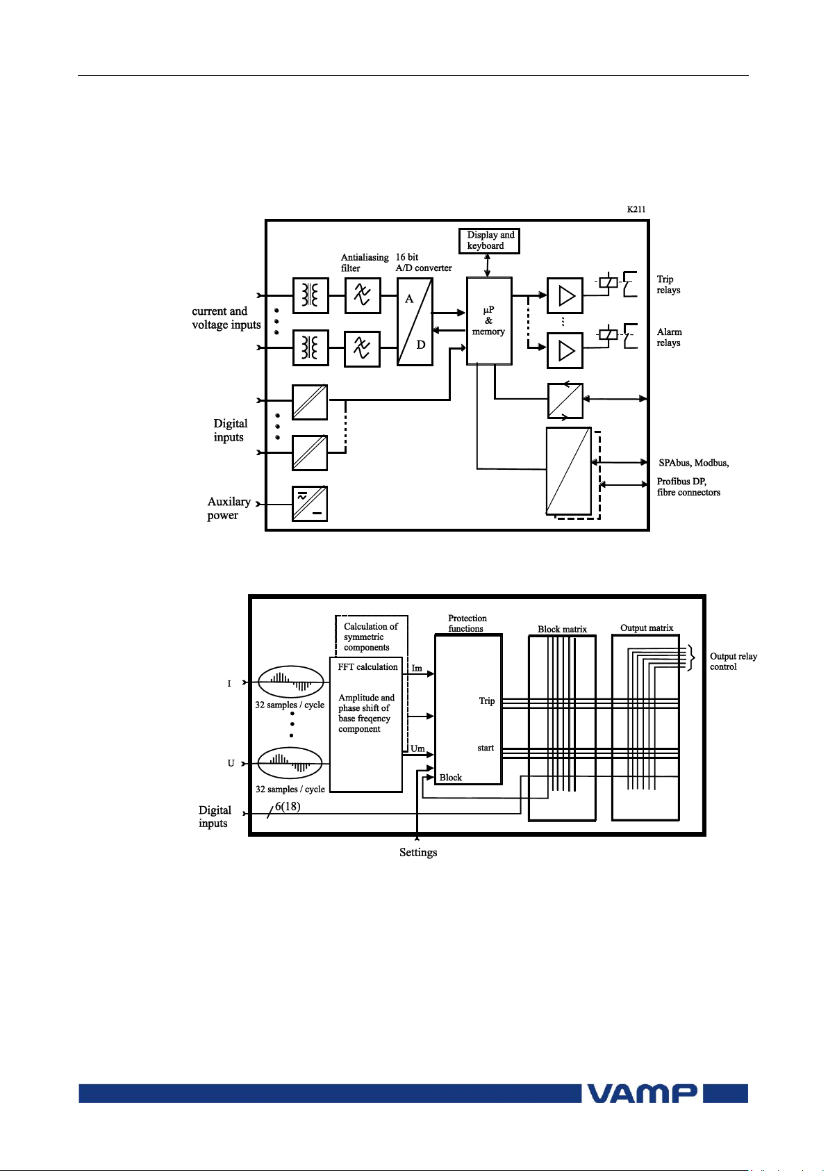
Figure 1.2-1 shows a principle block diagram of a numerical
device. The main components are the energizing inputs, digital
input elements, output relays, A/D converters and the micro
controller including memory circuits. Further, a device contains
a power supply unit and a human-machine interface (HMI).
Page 42
1.2 Principles of numerical
protection techniques
1 Introduction
Technical description
42
VAMP 24h support phone +358 (0)20 753 3264
VM55.EN005
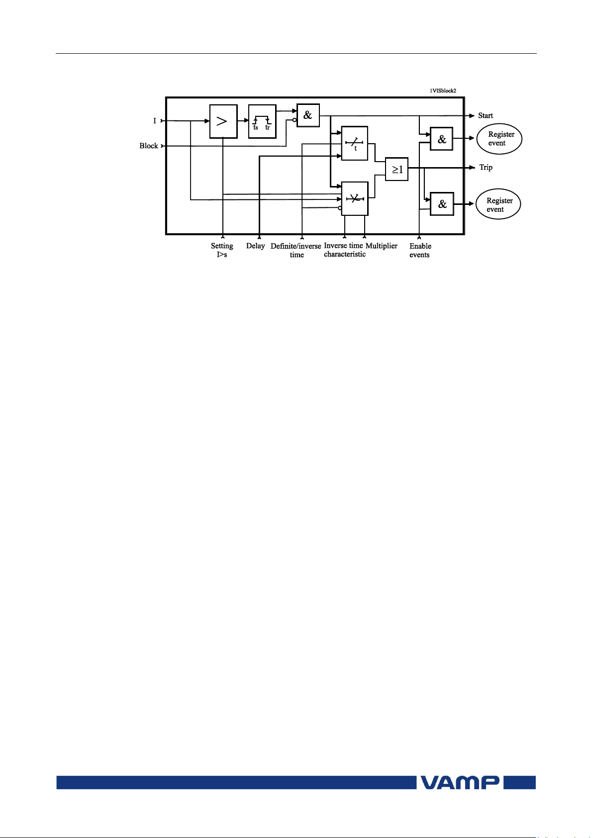
Figure 1.2-2 shows the heart of the numerical technology. That
is the main block diagram for calculated functions.
Figure 1.2-3 shows a principle diagram of a single-phase
overvoltage function.
Figure 1.2-1 Principle block diagram of the VAMP hardware
Figure 1.2-2 Block diagram of signal processing and protection software
Page 43
Technical description
1 Introduction
1.2 Principles of numerical
protection techniques
VM55.EN005
VAMP 24h support phone +358 (0)20 753 3264
43
Figure 1.2-3 Block diagram of a basic protection function
Page 44

2.1 Maximum number of protection
stages in one application
2 Protection functions
Technical description
44
VAMP 24h support phone +358 (0)20 753 3264
VM55.EN005
Ok = „„
The stage is idle and is measuring the analog
quantity for the protection. No fault detected.
Blocked
The stage is detecting a fault but blocked by
some reason.
Start
The stage is counting the operation delay.
Trip
The stage has tripped and the fault is still on.
2. Protection functions
Each protection stage can independently be enabled or disabled
according to the requirements of the intended application.
2.1. Maximum number of protection
stages in one application
The device limits the maximum number of enabled stages to
about 30, depending of the type of the stages. For more
information, please see the configuration instructions in
chapter 2.4 in the Operation and Configuration instruction.
2.2. General features of protection stages
Setting groups
Most stages have two setting groups. Changing between setting
groups can be controlled manually or using any of the digital
inputs, virtual inputs, virtual outputs or LED indicator signals.
By using virtual I/O the active setting group can be controlled
using the local panel display, any communication protocol or
using the inbuilt programmable logic functions.
Forcing start or trip condition for testing
The status of a protection stage can be one of the followings:
The blocking reason may be an active signal via the block
matrix from other stages, the programmable logic or any digital
input. Some stages also have inbuilt blocking logic. For more
details about block matrix, see chapter 5.6.
Page 45

Technical description
2 Protection functions
2.2 General features of protection
stages
VM55.EN005
VAMP 24h support phone +358 (0)20 753 3264
45
Forcing start or trip condition for testing purposes
There is a "Force flag" parameter which, when activated, allows
forcing the status of any protection stage to be "start" or "trip"
for a half second. By using this forcing feature any voltage
injection to the device is not necessary to check the output
matrix configuration, to check the wiring from the output
relays to the circuit breaker and also to check that
communication protocols are correctly transferring event
information to a SCADA system.
After testing the force flag will automatically reset 5-minute
after the last local panel push button activity.
The force flag also enables forcing of the output relays.
Start and trip signals
Every protection stage has two internal binary output signals:
start and trip. The start signal is issued when a fault has been
detected. The trip signal is issued after the configured
operation delay unless the fault disappears before the end of
the delay time.
Output matrix
Using the output matrix the user connects the internal start
and trip signals to the output relays and indicators. For more
details see chapter 5.4.
Blocking
Any protection function, except arc protection, can be blocked
with internal and external signals using the block matrix
(chapter 5.6). Internal signals are for example logic outputs and
start and trip signals from other stages and external signals
are for example digital and virtual inputs.
When a protection stage is blocked, it won't pick-up in case of a
fault condition is detected. If blocking is activated during the
operation delay, the delay counting is frozen until the blocking
goes off or the pick-up reason, i.e. the fault condition,
disappears. If the stage is already tripping, the blocking has no
effect.
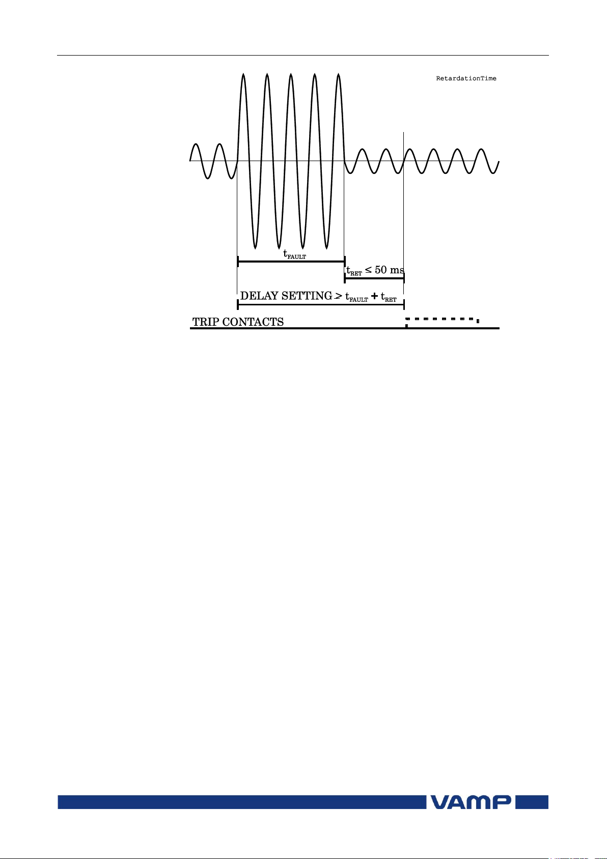
Retardation time
Retardation time is the time a protection relay needs to notice,
that a fault has been cleared during the operation time delay.
This parameter is important when grading the operation time
delay settings between relays.
Page 46
2.2 General features of protection
stages
2 Protection functions
Technical description
46
VAMP 24h support phone +358 (0)20 753 3264
VM55.EN005
Figure 2.2-1. Definition for retardation time. If the delay setting would be
slightly shorter, an unselective trip might occur (the dash line pulse).
For example when there is a big fault in an outgoing feeder, it
might start i.e. pick-up both the incoming and outgoing feeder
relay. However the fault must be cleared by the outgoing feeder
relay and the incoming feeder relay must not trip. Although the
operating delay setting of the incoming feeder is more than at
the outgoing feeder, the incoming feeder might still trip, if the
operation time difference is not big enough. The difference
must be more than the retardation time of the incoming feeder
relay plus the operating time of the outgoing feeder circuit
breaker.
Figure 2.2-1 shows an overvoltage fault seen by the incoming
feeder, when the outgoing feeder does clear the fault. If the
operation delay setting would be slightly shorter or if the fault
duration would be slightly longer than in the figure, an
unselective trip might happen (the dashed 40 ms pulse in the
figure). In VAMP devices the retardation time is less than 50
ms.
Page 47
Technical description
2 Protection functions
2.2 General features of protection
stages
VM55.EN005
VAMP 24h support phone +358 (0)20 753 3264
47
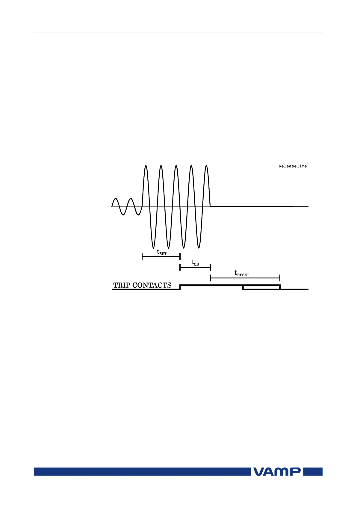
Reset time (release time)
Figure 2.2-2 shows an example of reset time i.e. release delay,
when the relay is clearing an overvoltage fault. When the
relay's trip contacts are closed the circuit breaker (CB) starts to
open. After the CB contacts are open current will still flow
through opened contacts through arc. The voltage is finally cut
off when the arc extinguishes at the next zero crossing of the
fault current. This is the start moment of the reset delay. After
the reset delay the trip contacts and start contact are opened.
Reset time varies from fault to fault depending on the fault
type. The reset time also depends on the specific protection
stage. The maximum reset time for each stage is specified in
chapter 9.3. For most stages it is less than 95 ms.
Figure 2.2-2. Reset time is the time it takes the trip or start relay contacts
to open after the fault has been cleared.
Hysteresis or dead band
When comparing a measured value against a pick-up value,
some amount of hysteresis is needed to avoid oscillation near
equilibrium situation. With zero hysteresis any noise in the
measured signal or any noise in the measurement itself would
cause unwanted oscillation between fault-on and fault-off
situations.
Page 48
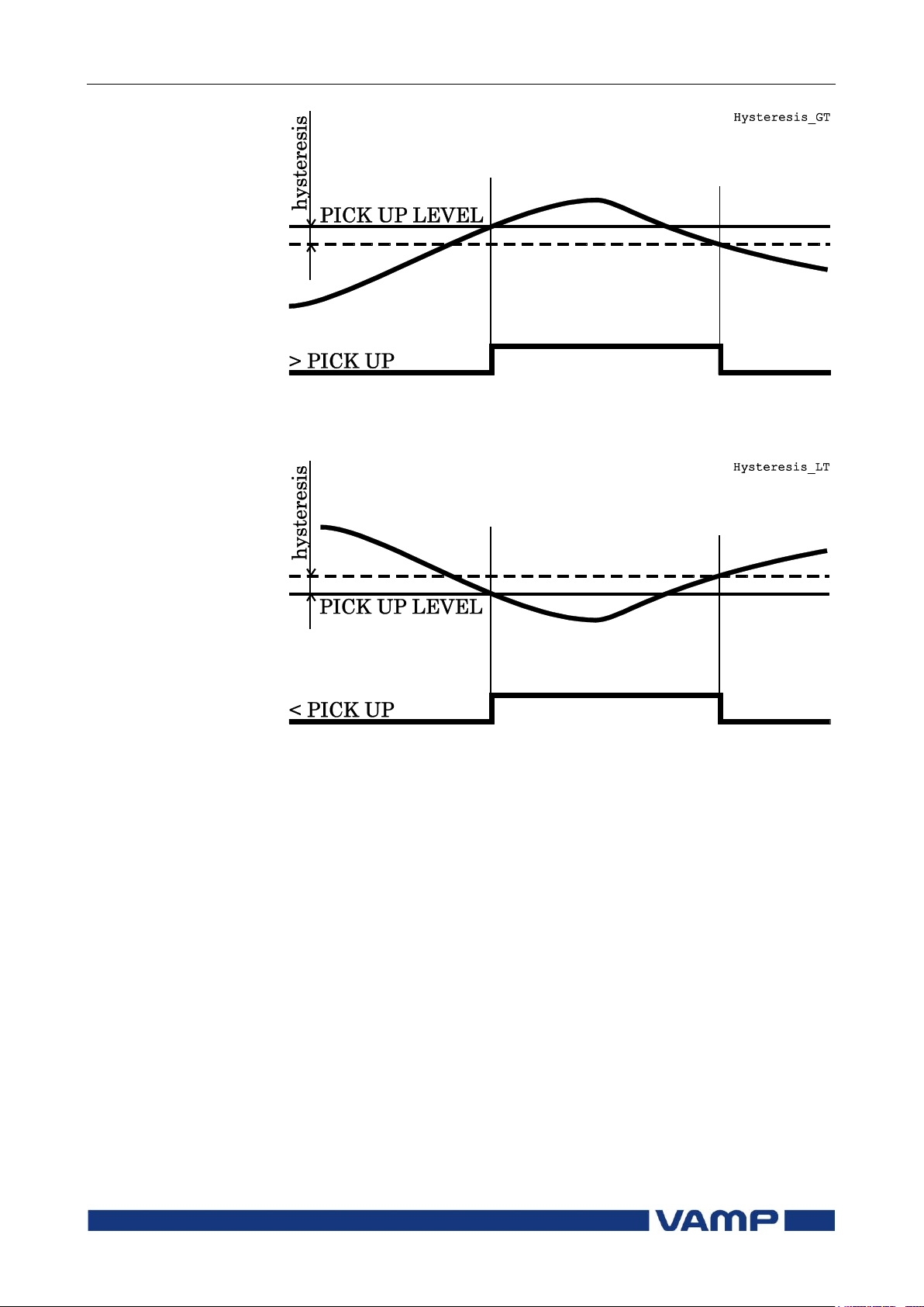
2.2 General features of protection
stages
2 Protection functions
Technical description
48
VAMP 24h support phone +358 (0)20 753 3264
VM55.EN005
Figure 2.2-3. Behaviour of a greater than comparator. For example in
overvoltage stages the hysteresis (dead band) acts according this figure.
Figure 2.2-4. Behaviour of a less than comparator. For example in undervoltage and under frequency stages the hysteresis (dead band) acts
according this figure.
Page 49
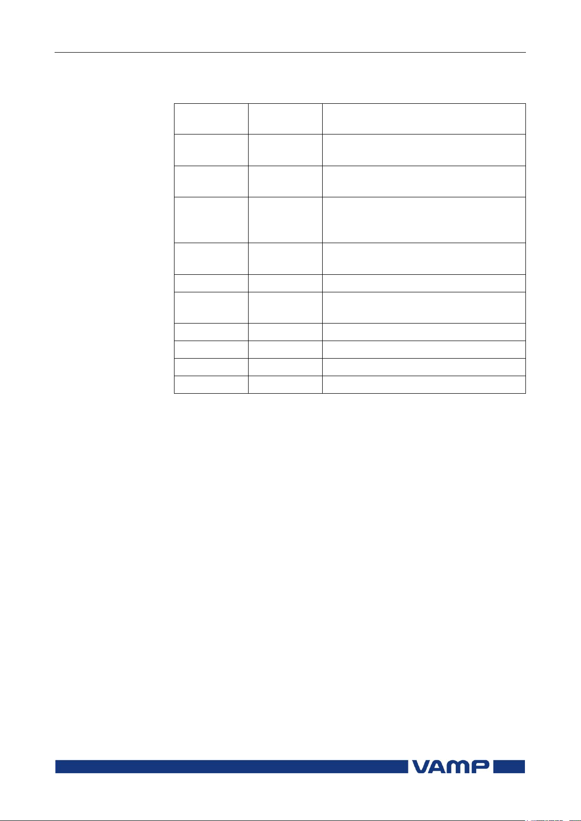
Technical description
2 Protection functions
2.3 List of protection functions
VM55.EN005
VAMP 24h support phone +358 (0)20 753 3264
49
IEEE/ANSI
code
IEC symbol
Function name
59
U>, U>>,
U>>>
Overvoltage protection
24
U/f>
Volts/hertz over excitation
protection
27P
U1<, U1<<
Positive sequence undervoltage
protection for generator
applications
27
U<, U<<,
U<<<
Undervoltage protection
59N
U0>, U0>>
Zero sequence voltage protection
81H/81L
f><, f>><<
Overfrequency and underfrequency
protection
81L
f<, f<<
Underfrequency protection
25
∆f, ∆U, ∆φ
Synchrocheck
50BF
CBFP
Circuit-breaker failure protection
99
Prg1…8
Programmable stages
2.3. List of protection functions
Page 50

2.4 Overvoltage protection U> (59)
2 Protection functions
Technical description
50
VAMP 24h support phone +358 (0)20 753 3264
VM55.EN005
2.4. Overvoltage protection U> (59)
Enable_U_Over VS_U_Over The overvoltage function measures the fundamental frequency
component of the line-to-line voltages regardless of the voltage
measurement mode (chapter 4.3). By using line-to-line voltages
any phase-to-ground over-voltages during earth faults have no
effect. (The earth fault protection functions will take care of
earth faults.) Whenever any of these three line-to-line voltages
exceeds the user's pick-up setting of a particular stage, this
stage picks up and a start signal is issued. If the fault situation
remains on longer than the user's operation time delay setting,
a trip signal is issued.
In rigidly earthed 4-wire networks with loads between phase
and neutral overvoltage protection may be needed for phase-toground voltages, too. In such applications the programmable
stages can be used. See chapter 2.12.
Three independent stages
There are three separately adjustable stages: U>, U>> and
U>>>. All the stages can be configured for definite time (DT)
operation characteristic.
Configurable release delay
The U> stage has a settable release delay, which enables
detecting intermittent faults. This means that the time counter
of the protection function does not reset immediately after the
fault is cleared, but resets after the release delay has elapsed.
If the fault appears again before the release delay time has
elapsed, the delay counter continues from the previous value.
This means that the function will eventually trip if faults are
occurring often enough.
Configurable hysteresis
The dead band is 3 % by default. It means that an overvoltage
fault is regarded as a fault until the voltage drops below 97 %
of the pick up setting. In a sensitive alarm application a
smaller hysteresis is needed. For example if the pick up setting
is about only 2 % above the normal voltage level, hysteresis
must be less than 2 %. Otherwise the stage will not release
after fault.
Setting groups
There are two settings groups available for each stage.
Switching between setting groups can be controlled by digital
inputs, virtual inputs (mimic display, communication, logic)
and manually.
Figure 2.4-1 shows the functional block diagram of the
overvoltage function stages U>, U>> and U>>>.
Page 51
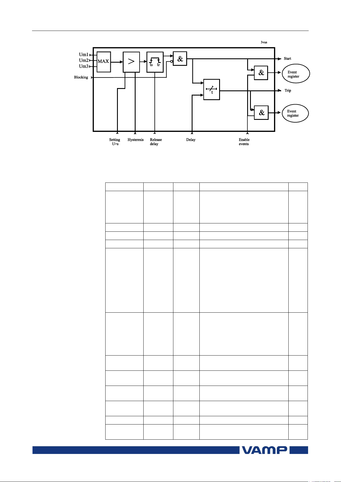
Technical description
2 Protection functions
2.4 Overvoltage protection U> (59)
VM55.EN005
VAMP 24h support phone +358 (0)20 753 3264
51
Parameter
Value
Unit
Description
Note
Status
Blocked
Start
Trip
Current status of the stage
F
F
SCntr
Cumulative start counter
C
TCntr
Cumulative trip counter
C
SetGrp
1 or 2
Active setting group
Set
SGrpDI
-
DIx
VIx
LEDx
VOx
Fx
Digital signal to select the
active setting group
None
Digital input
Virtual input
LED indicator signal
Virtual output
Function key
Set
Force
Off
On
Force flag for status forcing for
test purposes. This is a
common flag for all stages and
output relays, too.
Automatically reset by a 5minute timeout.
Set
Umax V
The supervised value. Max. of
U12, U23 and U31
U>, U>>,
U>>>
V Pick-up value scaled to
primary value
U>, U>>,
U>>>
%Un
Pick-up setting relative to UN
Set
t>, t>>,
t>>>
s Definite operation time
Set
RlsDly s
Release delay (U> stage only)
Set
Hyster
3
(default)
%
Dead band size i.e. hysteresis
Set
Figure 2.4-1 Block diagram of the three-phase overvoltage stages U>, U>>
and U>>>.
Parameters of the overvoltage stages U>, U>>, U>>> (59):
Page 52
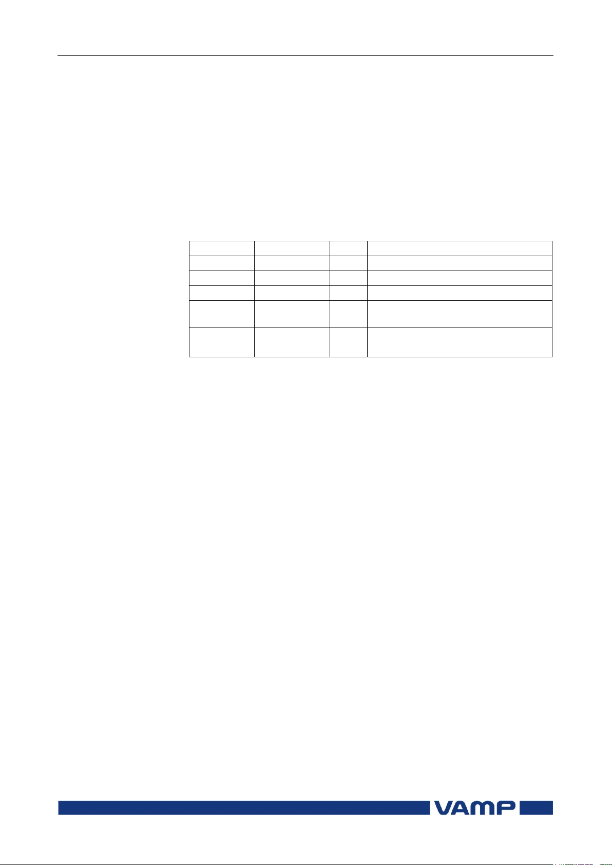
2.4 Overvoltage protection U> (59)
2 Protection functions
Technical description
52
VAMP 24h support phone +358 (0)20 753 3264
VM55.EN005
Parameter
Value
Unit
Description
yyyy-mm-dd
Time stamp of the recording, date
hh:mm:ss.ms
Time stamp, time of day
Flt %Un
Maximum fault voltage
EDly %
Elapsed time of the operating time
setting. 100% = trip
SetGrp
1
2
Active setting group during fault
For details of setting ranges see chapter 9.3.
Set = An editable parameter (password needed)
C = Can be cleared to zero
F = Editable when force flag is on
Recorded values of the latest eight faults
There are detailed information available of the eight latest
faults: Time stamp, fault voltage, elapsed delay and setting
group.
Recorded values of the overvoltage stages (8 latest faults)
U>, U>>, U>>> (59):
Page 53
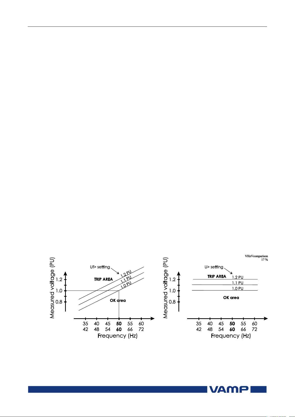
Technical description
2 Protection functions
2.5 Volts/hertz over-excitation
protection Uf> (24)
VM55.EN005
VAMP 24h support phone +358 (0)20 753 3264
53
2.5. Volts/hertz over-excitation protection
Uf> (24)
The saturation of any inductive network components like
transformers, inductors, motors and generators, depend on the
voltage and frequency. The lower the frequency, the lower is
the voltage at which the saturation begins.
The volts/hertz over-excitation protection stage is sensitive to
the voltage/frequency ratio instead of voltage only. Figure 2.5-1
shows the difference between volts/hertz and a standard
overvoltage function. The maximum of the three line-to-line
voltage is used regardless of the voltage measurement mode
(chapter 4.3). By using line-to-line voltages any phase-toground over-voltages during earth faults have no effect. (The
earth fault protection functions will take care of earth faults.)
The used net frequency is automatically adopted according the
local network frequency.
Overexcitation protection is needed for generators, which are
excitated even during start up and shut down. If such a
generator is connected to a unit transformer, also the unit
transformer needs volts/hertz over-excitation protection.
Another application is sensitive overvoltage protection of
modern transformers with no flux density margin in networks
with unstable frequency.
Setting groups
There are two settings groups available. Switching between
setting groups can be controlled by digital inputs, virtual
inputs (mimic display, communication, logic) and manually.
Figure 2.5-1 This figure shows the difference between volts/hertz and
normal overvoltage protection. The volts/hertz characteristics on the left
depend on the frequency while the standard overvoltage function on the
right is insensitive to frequency. The network frequency, 50 Hz or 60 Hz, is
automatically adopted by the relay.
Page 54
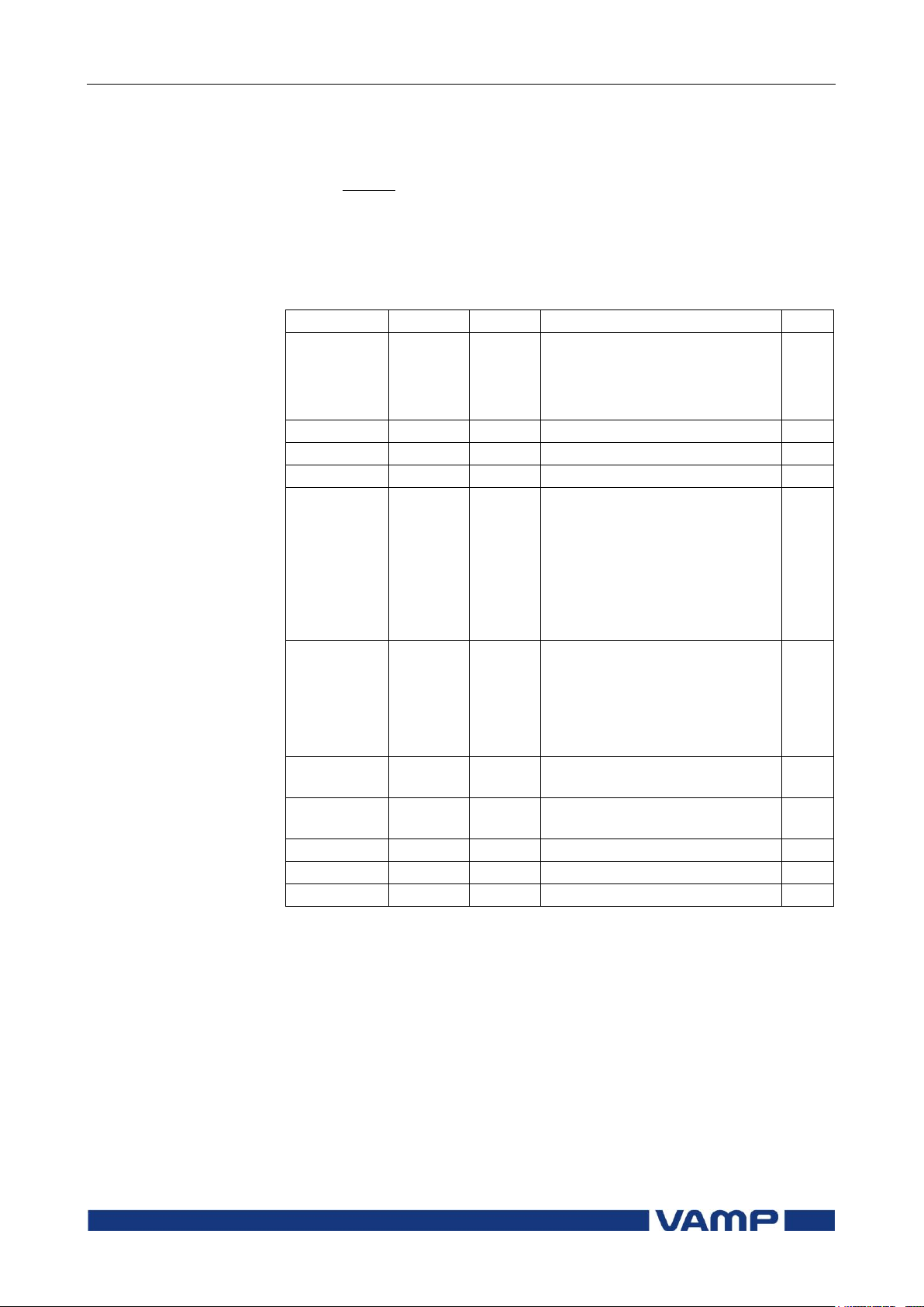
2.5 Volts/hertz over-excitation
protection Uf> (24)
2 Protection functions
Technical description
54
VAMP 24h support phone +358 (0)20 753 3264
VM55.EN005
RATED
RATED
f
U
PU 1
Parameter
Value
Unit
Description
Note
Status
Blocked
Start
Trip
Current status of the stage
F
F
SCntr
Cumulative start counter
C
TCntr
Cumulative trip counter
C
SetGrp
1 or 2
Active setting group
Set
SGrpDI
-
DIx
VIx
LEDx
VOx
Digital signal to select the
active setting group
None
Digital input
Virtual input
LED indicator signal
Virtual output
Set
Force
Off
On
Force flag for status forcing for
test purposes. This is a
common flag for all stages and
output relays, too.
Automatically reset by a 5minute timeout.
Set
Umax V
The supervised value. Max. of
U12, U23 and U31
f
Hz
The supervised frequency
value
U/f %
Calculated Umax/f
Uf> %
Pick-up setting
Set
t> s
Definite operation time
Set
The setting unit is per unit (PU).
, where
U
is the nominal voltage of the protected device and f
RATED
RATED
is the basic network frequency.
Parameters of the volts/hertz over-excitation stage Uf> (24)
For details of setting ranges see chapter 9.3.
Set = An editable parameter (password needed)
C = Can be cleared to zero
F = Editable when force flag is on
Recorded values of the latest eight faults
There are detailed information available of the eight latest
faults: Time stamp, fault voltage, fault frequency, elapsed delay
and setting group.
Page 55
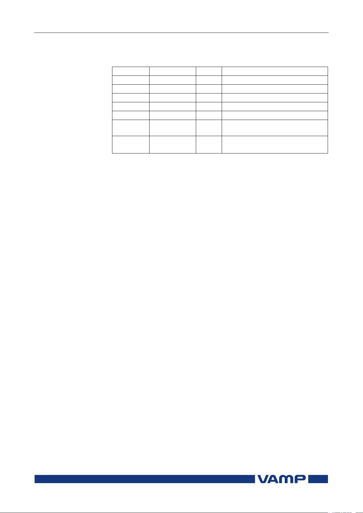
Technical description
2 Protection functions
2.5 Volts/hertz over-excitation
protection Uf> (24)
VM55.EN005
VAMP 24h support phone +358 (0)20 753 3264
55
Parameter
Value
Unit
Description
yyyy-mm-dd
Time stamp of the recording, date
hh:mm:ss.ms
Time stamp, time of day
Flt %
Fault value V/Hz
U %Un
Fault voltage
f Hz
Fault frequency
EDly %
Elapsed time of the operating time
setting. 100% = trip
SetGrp
1
2
Active setting group during fault
Recorded values of the volts/hertz over-excitation stage
Uf> (8 latest faults) Uf> (24)
Page 56

2.6 Undervoltage protection U1<
(27P)
2 Protection functions
Technical description
56
VAMP 24h support phone +358 (0)20 753 3264
VM55.EN005
2.6. Undervoltage protection U
This a special undervoltage protection for generator
applications, where the voltage is measured at the generator
side of the generator circuit breaker. There are special self
blocking features for starting up and shutting down a
generator.
This undervoltage function measures the positive sequence of
fundamental frequency component U1 of the measured voltages
(for calculation of U1 see chapter 4.4). By using positive
sequence all the three phases are supervised with one value
and in case the generator looses connection to the network (loss
of mains), the undervoltage situation is detected faster than by
using just the minimum of the three line-to-line voltages.
Whenever the positive sequence voltage U1 drops below the
user's pick-up setting of a particular stage, this stage picks up
and a start signal is issued. If the fault situation remains on
longer than the user's operation time delay setting, a trip
signal is issued.
Blocking during VT fuse failure
< (27P)
1
As all the protection stages the undervoltage function can be
blocked with any internal or external signal using the block
matrix. For example if the secondary voltage of one of the
measuring transformers disappears because of a fuse failure
(See VT supervision function in chapter 3.5). The blocking
signal can also be a signal from the user's logic (see chapter
5.8).
Self blocking at very low voltage
The stages will be blocked when the voltage is below a separate
low voltage blocking setting. With this setting, LVBlk, both
stages are blocked, when the voltage U1 drops below the given
limit. The idea is to avoid purposeless alarms, when the
generator is not running. The LVBlk setting is common for
both stages. The self blocking can not be disabled.
Initial self blocking
When the voltage U1 has been below the block limit, the stages
will be blocked until the pick-up setting has been reached.
Page 57
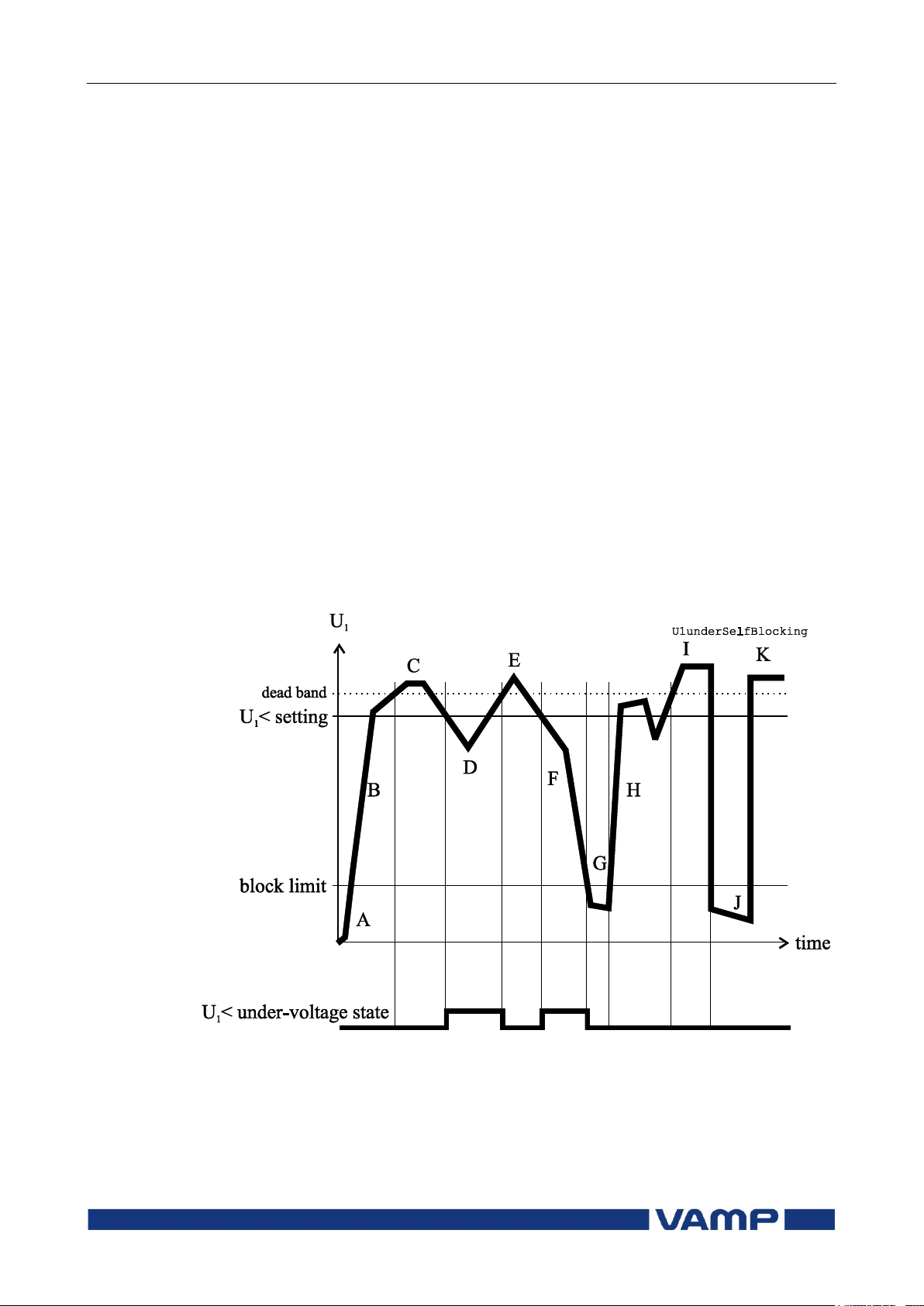
Technical description
2 Protection functions
2.6 Undervoltage protection U1<
(27P)
VM55.EN005
VAMP 24h support phone +358 (0)20 753 3264
57
A
The positive sequence voltage U1 is below the block
limit. This is not regarded as an under voltage
situation.
B
The positive sequence voltage U1 is above the block
limit but below the pick-up level. However, this is not
regarded as an under voltage situation, because the
voltage has never been above the pick-up level since
being below the block limit.
C
Voltage is OK, because it is above the pick-up limit.
D
This is an under voltage situation.
E
Voltage is OK.
F
This is an under voltage situation.
G
Voltage is under block limit and this is not regarded as
an under voltage situation.
H
Same as B.
I
Voltage is OK.
J
Same as G
K
Voltage is OK.
Figure 2.6-1 shows an example of low voltage self blocking.
Figure 2.6-1 Positive sequence under voltage state and block limit.
Two independent stages
There are two separately adjustable stages: U1< and U1<<.
Both stages can be configured for definite time (DT) operation
characteristic.
Page 58
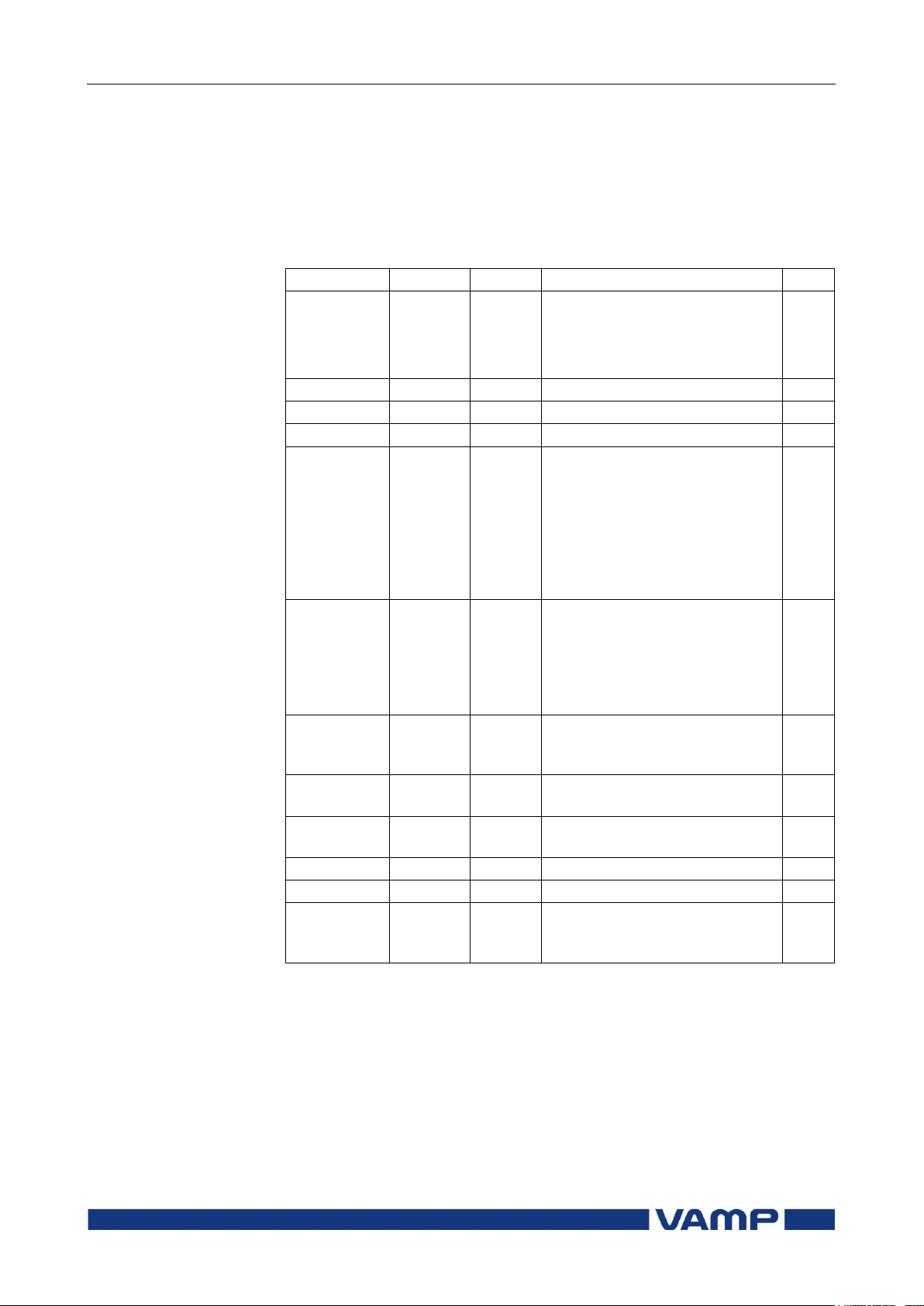
2.6 Undervoltage protection U1<
(27P)
2 Protection functions
Technical description
58
VAMP 24h support phone +358 (0)20 753 3264
VM55.EN005
Parameter
Value
Unit
Description
Note
Status
Blocked
Start
Trip
Current status of the stage
F
F
SCntr
Cumulative start counter
C
TCntr
Cumulative trip counter
C
SetGrp
1 or 2
Active setting group
Set
SGrpDI
-
DIx
VIx
LEDx
VOx
Digital signal to select the
active setting group
None
Digital input
Virtual input
LED indicator signal
Virtual output
Set
Force
Off
On
Force flag for status forcing for
test purposes. This is a
common flag for all stages and
output relays, too.
Automatically reset by a 5minute timeout.
Set
U1 V
The supervised positive
sequence voltage in primary
volts
U1 %
The supervised positive
sequence voltage of Un/3
U1<, U1<<
V Pick-up value scaled to
primary value
U1<, U1<<
%
Pick-up setting of Un/3
Set
t<, t<< s
Definite operation time
Set
LVBlk
%Un
Low limit for self blocking.
This is a common setting for
both stages.
Set
Setting groups
There are two settings groups available for both stages.
Switching between setting groups can be controlled by digital
inputs, virtual inputs (mimic display, communication, logic)
and manually.
Parameters of the under voltage stages U1<, U1<< (27P)
For details of setting ranges see chapter 9.3.
Set = An editable parameter (password needed)
C = Can be cleared to zero
F = Editable when force flag is on
Recorded values of the latest eight faults
There are detailed information available of the eight latest
faults: Time stamp, fault voltage, elapsed delay and setting
group.
Page 59

Technical description
2 Protection functions
2.6 Undervoltage protection U1<
(27P)
VM55.EN005
VAMP 24h support phone +358 (0)20 753 3264
59
Parameter
Value
Unit
Description
yyyy-mm-dd
Time stamp of the recording, date
hh:mm:ss.ms
Time stamp, time of day
Flt %Un
Minimum fault voltage
EDly %
Elapsed time of the operating time
setting. 100% = trip
SetGrp
1
2
Active setting group during fault
Recorded values of the undervoltage stages (8 latest faults)
U1<, U1<< (27P)
Page 60

2.7 Undervoltage protection U< (27)
2 Protection functions
Technical description
60
VAMP 24h support phone +358 (0)20 753 3264
VM55.EN005
A
The maximum of the three line-to-line voltages U
LLmax
is below the block limit. This is not regarded as an
under voltage situation.
B
The voltage U
LLmin
is above the block limit but below
the pick-up level. This is an undervoltage situation.
C
Voltage is OK, because it is above the pick-up limit.
D
This is an under voltage situation.
E
Voltage is OK.
F
This is an under voltage situation.
G
The voltage U
LLmin
is under block limit and this is not
regarded as an under voltage situation.
H
This is an under voltage situation.
I
Voltage is OK.
J
Same as G
K
Voltage is OK.
2.7. Undervoltage protection U< (27)
Enable_U_Under VS_U_Under This is a basic undervoltage protection. The function measures
the three line-to-line voltages and whenever the smallest of
them drops below the user's pick-up setting of a particular
stage, this stage picks up and a start signal is issued. If the
fault situation remains on longer than the user's operation time
delay setting, a trip signal is issued.
Self blocking at very low voltage
The stages can be blocked with a separate low limit setting.
With this setting, the particular stage will be blocked, when the
biggest of the three line-to-line voltages drops below the given
limit. The idea is to avoid purposeless tripping, when voltage is
switched off. If the operating time is less than 0.08 s, the
blocking level setting should not be less than 15 % to the
blocking action to be enough fast. The self blocking can be
disabled by setting the low voltage block limit equal to zero.
Figure 2.7-1shows an example of low voltage self blocking.
Page 61
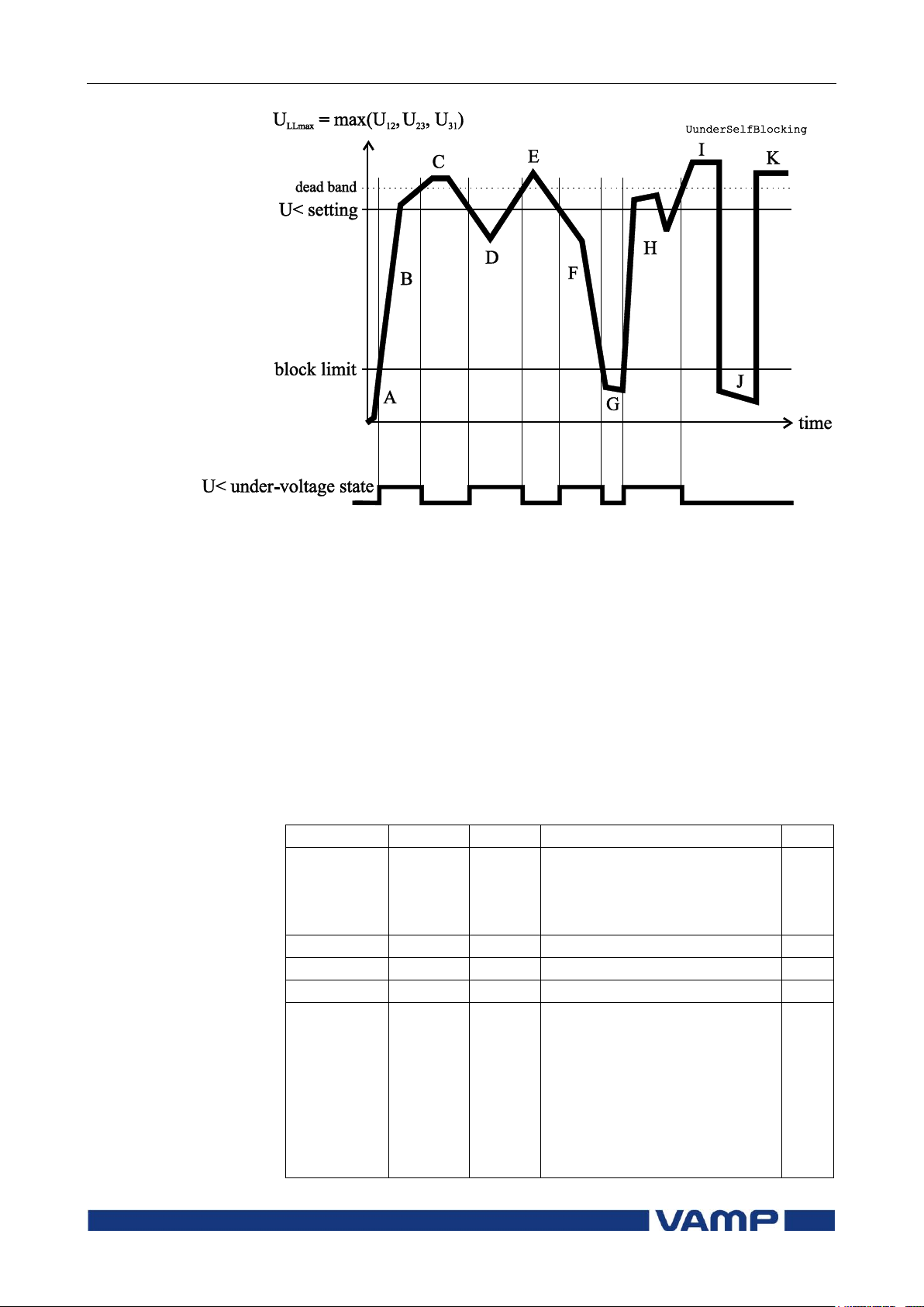
Technical description
2 Protection functions
2.7 Undervoltage protection U< (27)
VM55.EN005
VAMP 24h support phone +358 (0)20 753 3264
61
Parameter
Value
Unit
Description
Note
Status
Blocked
Start
Trip
Current status of the stage
F
F
SCntr
Cumulative start counter
C
TCntr
Cumulative trip counter
C
SetGrp
1 or 2
Active setting group
Set
SGrpDI
-
DIx
VIx
LEDx
VOx
Fx
Digital signal to select the
active setting group
None
Digital input
Virtual input
LED indicator signal
Virtual output
Function key
Set
Figure 2.7-1.Under voltage state and block limit.
Three independent stages
There are three separately adjustable stages: U<, U<< and
U<<<. All these stages can be configured for definite time (DT)
operation characteristic.
Setting groups
There are two settings groups available for all stages.
Switching between setting groups can be controlled by digital
inputs, virtual inputs (mimic display, communication, logic)
and manually.
Parameters of the under voltage stages U<, U<<, U<<< (27):
Page 62

2.7 Undervoltage protection U< (27)
2 Protection functions
Technical description
62
VAMP 24h support phone +358 (0)20 753 3264
VM55.EN005
Parameter
Value
Unit
Description
Note
Force
Off
On
Force flag for status forcing for
test purposes. This is a
common flag for all stages and
output relays, too.
Automatically reset by a 5minute timeout.
Set
MinU V
The supervised minimum of
line-to-line voltages in primary
volts
U<, U<<,
U<<<
V Pick-up value scaled to
primary value
U<, U<<,
U<<<
%Un
Pick-up setting
Set
t<, t<<,
t<<<
S Definite operation time
Set
LVBlk
%Un
Low limit for self blocking
Set
RlsDly S
Release delay (U< stage only)
Set
Hyster
Default
3.0 %
%
Dead band setting
Set
Parameter
Value
Unit
Description
yyyy-mm-dd
Time stamp of the recording, date
hh:mm:ss.ms
Time stamp, time of day
Flt %Un
Minimum fault voltage
EDly %
Elapsed time of the operating time
setting. 100% = trip
PreFlt
%Un
Supervised value before fault, 1 s
average value.
SetGrp
1
2
Active setting group during fault
For details of setting ranges see chapter 9.3.
Set = An editable parameter (password needed)
C = Can be cleared to zero
F = Editable when force flag is on
Recorded values of the latest eight faults
There are detailed information available of the eight latest
faults for each of the stages: Time stamp, fault voltage, elapsed
delay, voltage before the fault and setting group.
Recorded values of the undervoltage stages (8 latest faults)
U<, U<<, U<<< (27):
Page 63

Technical description
2 Protection functions
2.8 Zero sequence voltage
protection U0> (59N)
VM55.EN005
VAMP 24h support phone +358 (0)20 753 3264
63
2.8. Zero sequence voltage protection U
(59N)
The zero sequence voltage protection is used as unselective
backup for earth faults and also for selective earth fault
protections for motors having a unit transformer between the
motor and the busbar.
This function is sensitive to the fundamental frequency
component of the zero sequence voltage. The attenuation of the
third harmonic is more than 60 dB. This is essential, because
3n harmonics exist between the neutral point and earth also
when there is no earth fault.
Whenever the measured value exceeds the user's pick-up
setting of a particular stage, this stage picks up and a start
signal is issued. If the fault situation remains on longer than
the user's operation time delay setting, a trip signal is issued.
Measuring the zero sequence voltage
The zero sequence voltage is either measured with three
voltage transformers (e.g. broken delta connection), one voltage
transformer between the motor's neutral point and earth (see
chapter 4.3):
0
>
U
: The zero sequence voltage is measured with voltage
0
transformer(s) for example using a broken delta connection.
The setting values are relative to the VT0 secondary voltage
defined in configuration.
NOTE! The U0 signal must be connected according the connection diagram
(Figure 8.7-3) in order to get a correct polarization.
Two independent stages
There are two separately adjustable stages: U0> and U0>>.
Both stages can be configured for definite time (DT) operation
characteristic.
The zero sequence voltage function comprises two separately
adjust-table zero sequence voltage stages (stage U0> and U0>>).
Setting groups
There are two settings groups available for both stages.
Switching between setting groups can be controlled by digital
inputs, virtual inputs (mimic display, communication, logic)
and manually.
Page 64
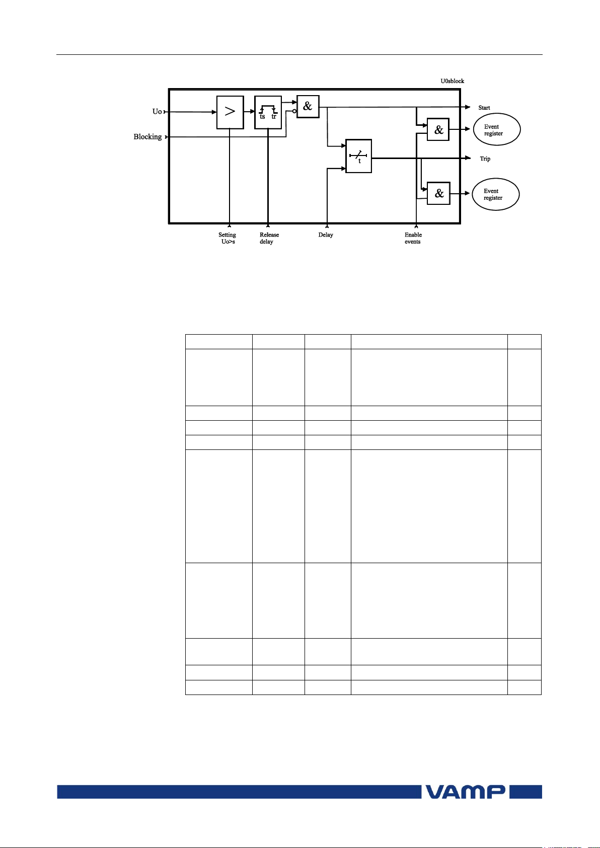
2.8 Zero sequence voltage
protection U0> (59N)
2 Protection functions
Technical description
64
VAMP 24h support phone +358 (0)20 753 3264
VM55.EN005
Parameter
Value
Unit
Description
Note
Status
Blocked
Start
Trip
Current status of the stage
F
F
SCntr
Cumulative start counter
C
TCntr
Cumulative trip counter
C
SetGrp
1 or 2
Active setting group
Set
SGrpDI
-
DIx
VIx
LEDx
VOx
Fx
Digital signal to select the
active setting group
None
Digital input
Virtual input
LED indicator signal
Virtual output
Function key
Set
Force
Off
On
Force flag for status forcing for
test purposes. This is a
common flag for all stages and
output relays, too.
Automatically reset by a 5minute timeout.
Set
Uo %
The supervised value relative
to Un/3
Uo>, Uo>>
%
Pick-up value relative to Un/3
Set
t>, t>> s
Definite operation time
Set
Figure 2.8-1 Block diagram of the zero sequence voltage stages U0> and
U0>>
Parameters of the residual overvoltage stages U0>, U0>>
(59N):
For details of setting ranges see chapter 9.3.
Set = An editable parameter (password needed)
C = Can be cleared to zero
F = Editable when force flag is on
Page 65
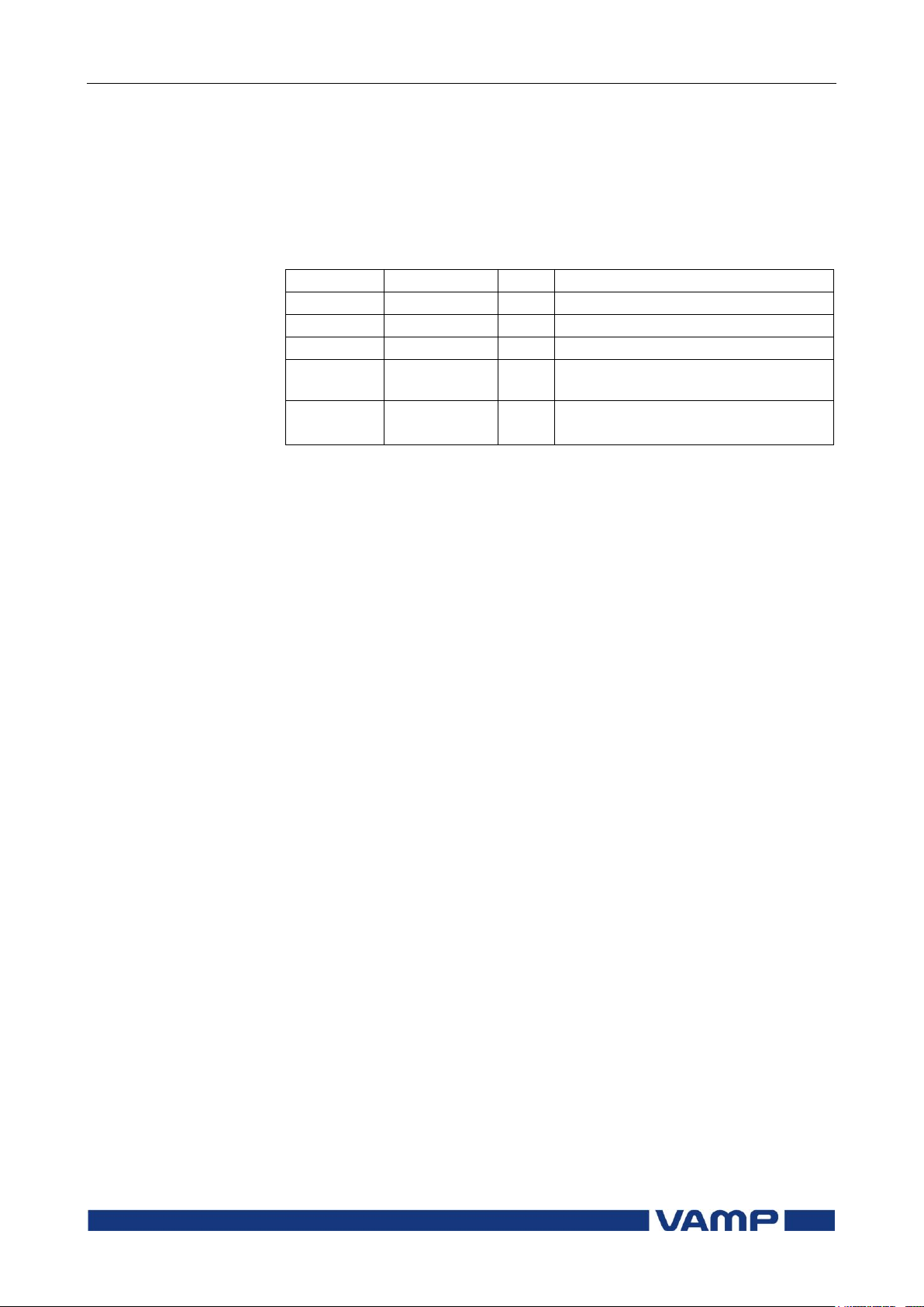
Technical description
2 Protection functions
2.8 Zero sequence voltage
protection U0> (59N)
VM55.EN005
VAMP 24h support phone +358 (0)20 753 3264
65
Parameter
Value
Unit
Description
yyyy-mm-dd
Time stamp of the recording, date
hh:mm:ss.ms
Time stamp, time of day
Flt %
Fault voltage relative to Un/3
EDly %
Elapsed time of the operating time
setting. 100% = trip
SetGrp
1
2
Active setting group during fault
Recorded values of the latest eight faults
There are detailed information available of the eight latest
faults: Time stamp, fault voltage, elapsed delay and setting
group.
Recorded values of the residual overvoltage stages
U0>, U0>> (59N):
Page 66

2.9 Overfrequency and
underfrequency Protection f>, f<
(81H/81L)
2 Protection functions
Technical description
66
VAMP 24h support phone +358 (0)20 753 3264
VM55.EN005
2.9. Overfrequency and underfrequency
Protection f>, f< (81H/81L)
Enable_f VS_f_Over Frequency protection is used for load sharing, loss of mains
detection and as a backup protection for over-speeding.
The frequency function measures the frequency from the two
first voltage inputs. At least one of these two inputs must have
a voltage connected to be able to measure the frequency.
Whenever the frequency crosses the user's pick-up setting of a
particular stage, this stage picks up and a start signal is
issued. If the fault situation remains on longer than the user's
operation delay setting, a trip signal is issued. For situations,
where no voltage is present an adapted frequency is used. See
chapter 1.2.
Protection mode for f>< and f>><< stages
These two stages can be configured either for overfrequency or
for underfrequency.
Under voltage self blocking of underfrequency stages
The underfrequency stages are blocked when biggest of the
three line-to-line voltages is below the low voltage block limit
setting. With this common setting, LVBlk, all stages in
underfrequency mode are blocked, when the voltage drops
below the given limit. The idea is to avoid purposeless alarms,
when the voltage is off.
Initial self blocking of underfrequency stages
When the biggest of the three line-to-line voltages has been
below the block limit, the under frequency stages will be
blocked until the pick-up setting has been reached.
Four independent frequency stages
There are four separately adjustable frequency stages: f><,
f>><<, f<, f<<. The two first stages can be configured for either
overfrequency or underfrequency usage. So totally four
underfrequency stages can be in use simultaneously. Using the
programmable stages even more can be implemented (chapter
2.12). All the stages have definite operation time delay (DT).
Setting groups
There are two settings groups available for each stage.
Switching between setting groups can be controlled by digital
inputs, virtual inputs (mimic display, communication, logic)
and manually.
Page 67
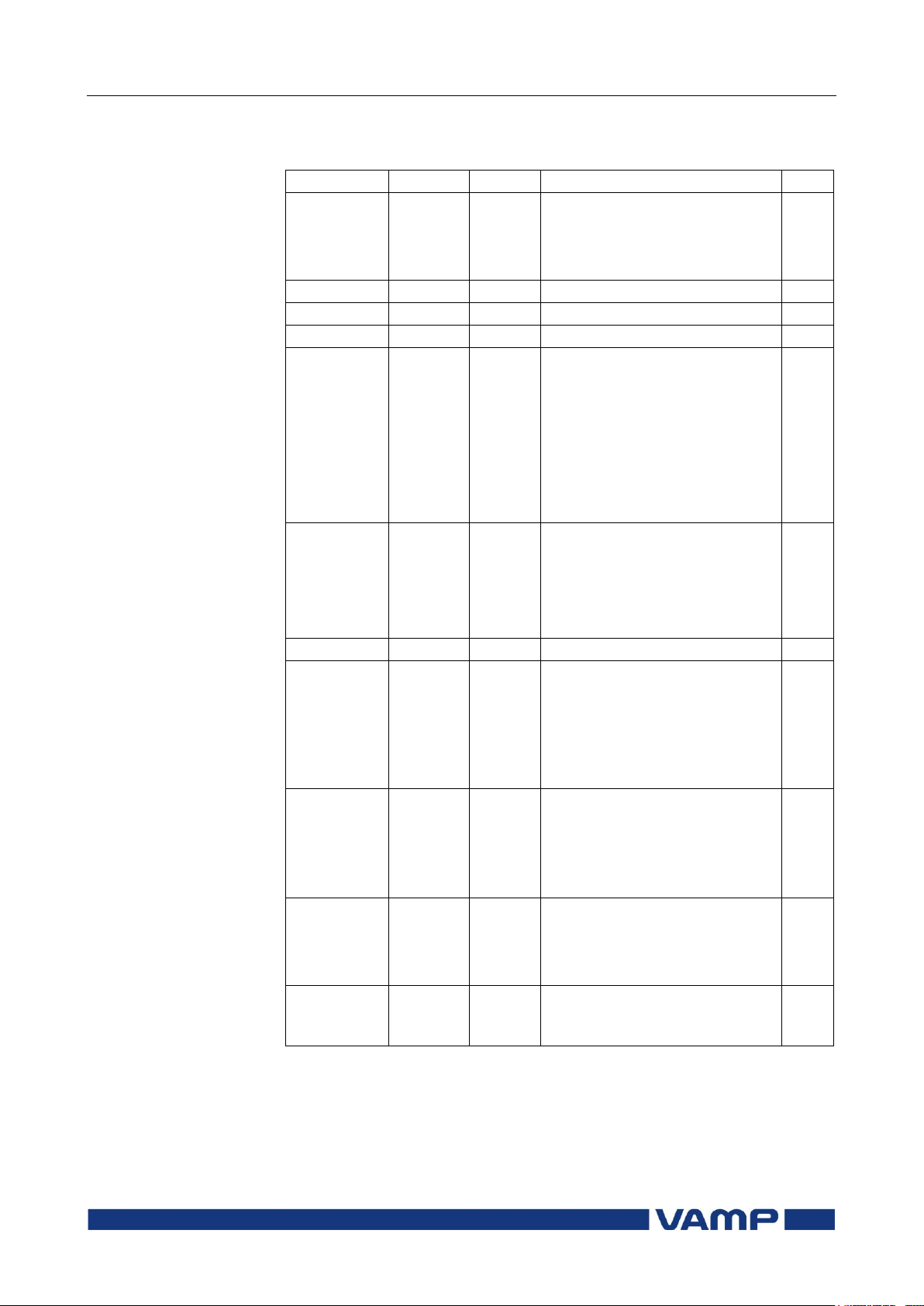
Technical description
2 Protection functions
2.9 Overfrequency and
underfrequency Protection f>, f<
(81H/81L)
VM55.EN005
VAMP 24h support phone +358 (0)20 753 3264
67
Parameter
Value
Unit
Description
Note
Status
Blocked
Start
Trip
Current status of the stage
F
F
SCntr
Cumulative start counter
C
TCntr
Cumulative trip counter
C
SetGrp
1 or 2
Active setting group
Set
SGrpDI
-
DIx
VIx
LEDx
VOx
Fx
Digital signal to select the
active setting group
None
Digital input
Virtual input
LED indicator signal
Virtual output
Function key
Set
Force
Off
On
Force flag for status forcing for
test purposes. This is a
common flag for all stages and
output relays, too.
Automatically reset by a 5minute timeout.
Set
f Hz
The supervised value.
fX
fXX
f<
f<<
Hz
Pick-up value
Over/under stage f><. See
Mode
Over/under stage f>><<.
Under stage f<
Under stage f<<
Set
tX
tXX
t<
t<<
s Definite operation time
f>< stage
f>><< stage
f< stage
f<< stage
Set
Mode
>
<
Operation mode. (only for f><
and f>><<)
Overfrequency mode
Underfrequency mode
Set
LVblck
%Un
Low limit for self blocking.
This is a common setting for
all four stages.
Set
Parameters of the over & underfrequency stages
f><, f>><<, f<, f<< (81H/81L):
For details of setting ranges see chapter 9.3.
Set = An editable parameter (password needed)
C = Can be cleared to zero
F = Editable when force flag is on
Page 68
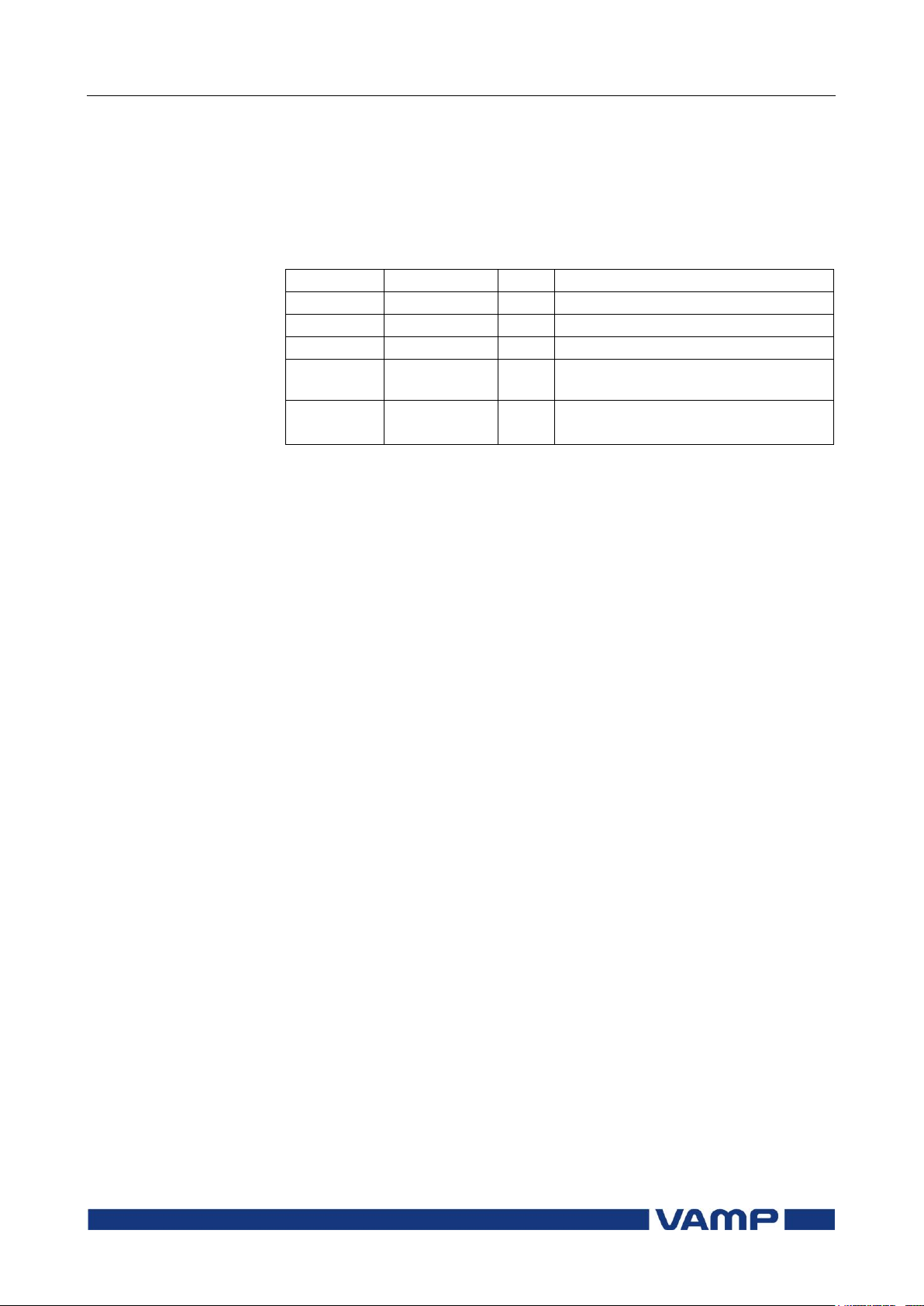
2.9 Overfrequency and
underfrequency Protection f>, f<
(81H/81L)
2 Protection functions
Technical description
68
VAMP 24h support phone +358 (0)20 753 3264
VM55.EN005
Parameter
Value
Unit
Description
yyyy-mm-dd
Time stamp of the recording, date
hh:mm:ss.ms
Time stamp, time of day
Flt Hz
Faulty frequency
EDly %
Elapsed time of the operating time
setting. 100% = trip
SetGrp
1
2
Active setting group during fault
Recorded values of the latest eight faults
There are detailed information available of the eight latest
faults: Time stamp, frequency during fault, elapsed delay and
setting group.
Recorded values of the over & under frequency stages (8
latest faults) f><, f>><<, f<, f<< (81H/81L):
Page 69

Technical description
2 Protection functions
2.10 Synchrocheck (25)
VM55.EN005
VAMP 24h support phone +358 (0)20 753 3264
69
Parameter
Values
Unit
Default
Description
Side
U12/U12y;
-
U12/U12z
Voltage selection. The
stage 1 has fixed voltages
U12/U12y or U12/U1y
CBObj
Obj1
-
Obj1
The selected object for CB
control. The synchrocheck
closing command will use
the closing command of
the selected object.
NOTE! The stage 1 is
always using the object 1.
Smode
Async;
Sync; Off
-
Sync
Synchrocheck mode.
Off = only voltage check
Async = the function
checks dU, df and dangle.
Furthermore, the
frequency slip, df,
determines the remaining
time for closing. This time
must be longer than “CB
time”.
Sync mode =
Synchronization is tried to
make exactly when angle
difference is zero. In this
mode df-setting should be
enough small (<0.3Hz).
2.10. Synchrocheck (25)
VS_Sync VS_Scaling Enable_Sync Synchrocheck is a function that will check synchronism in both
sides of the opened circuit breaker. The function will monitor
voltage amplitude, frequency and phase angle difference
between two voltages. The reference for synchrocheck can be
phase to ground or phase to phase voltage.
Voltage measuring mode must be selected to enable
synchrocheck from the desired reference. Available voltage
modes are 3LN/LLy for phase to phase voltage reference and
3LN/LNy for phase to ground reference.
The voltage used for sychrochecking is always phase-to-phase
voltage U
Setting parameters of synchrocheck stage SyC1 (25):
or phase to ground voltage U1
12
Page 70
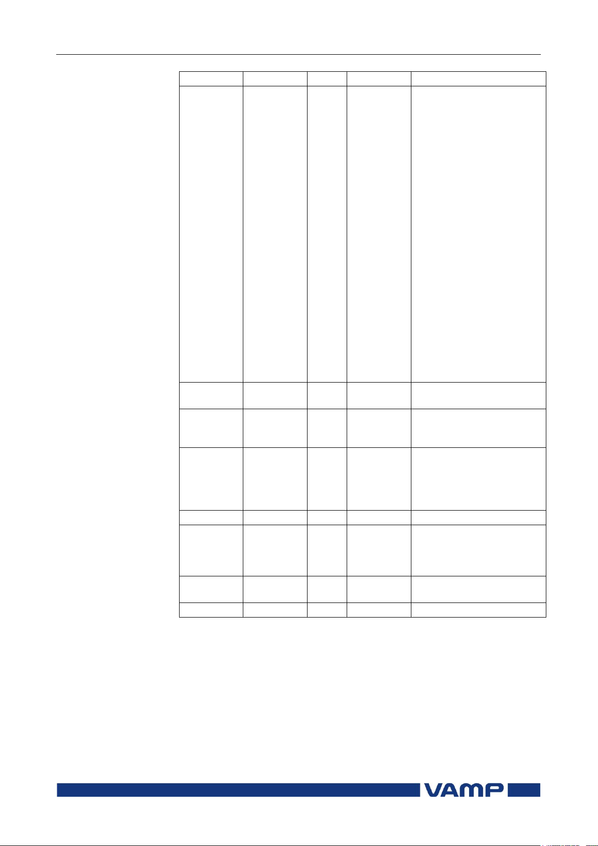
2.10 Synchrocheck (25)
2 Protection functions
Technical description
70
VAMP 24h support phone +358 (0)20 753 3264
VM55.EN005
Parameter
Values
Unit
Default
Description
Umode
-,
DD,
DL,
LD,
DD/DL,
DD/LD,
DL/LD,
DD/DL/LD
- - Voltage check mode:
The first letter refers to
the reference voltage and
the second letter refers to
the comparison voltage.
D means that the side
must be “dead” when
closing (dead = The
voltage below the dead
voltage limit setting)
L means that the side
must be “live” when
closing (live = The voltage
higher than the live
voltage limit setting)
Example: DL mode for
stage 1:
The U12 side must be
“dead” and the U12y side
must be “live”.
Cbtime
0.04 … 0.6
s
0.1
Typical closing time of the
circuit-breaker.
Dibypass
Digital
inputs
- - Bypass input. If the input
is active, the function is
bypassed.
Bypass
0; 1 - 0
The bypass status. “1”
means that the function is
bypassed. This parameter
can also be used for
manual bypass.
CBCtrl
Open;Close
- - Circuit-breaker control
ShowInfo
Off; On
-
On
Additional information
display about the
sychrocheck status to the
mimic.
SGrpDI
Digital
inputs
- - The input for changing
the setting group.
SetGrp
1; 2 - 1
The active setting group.
Page 71
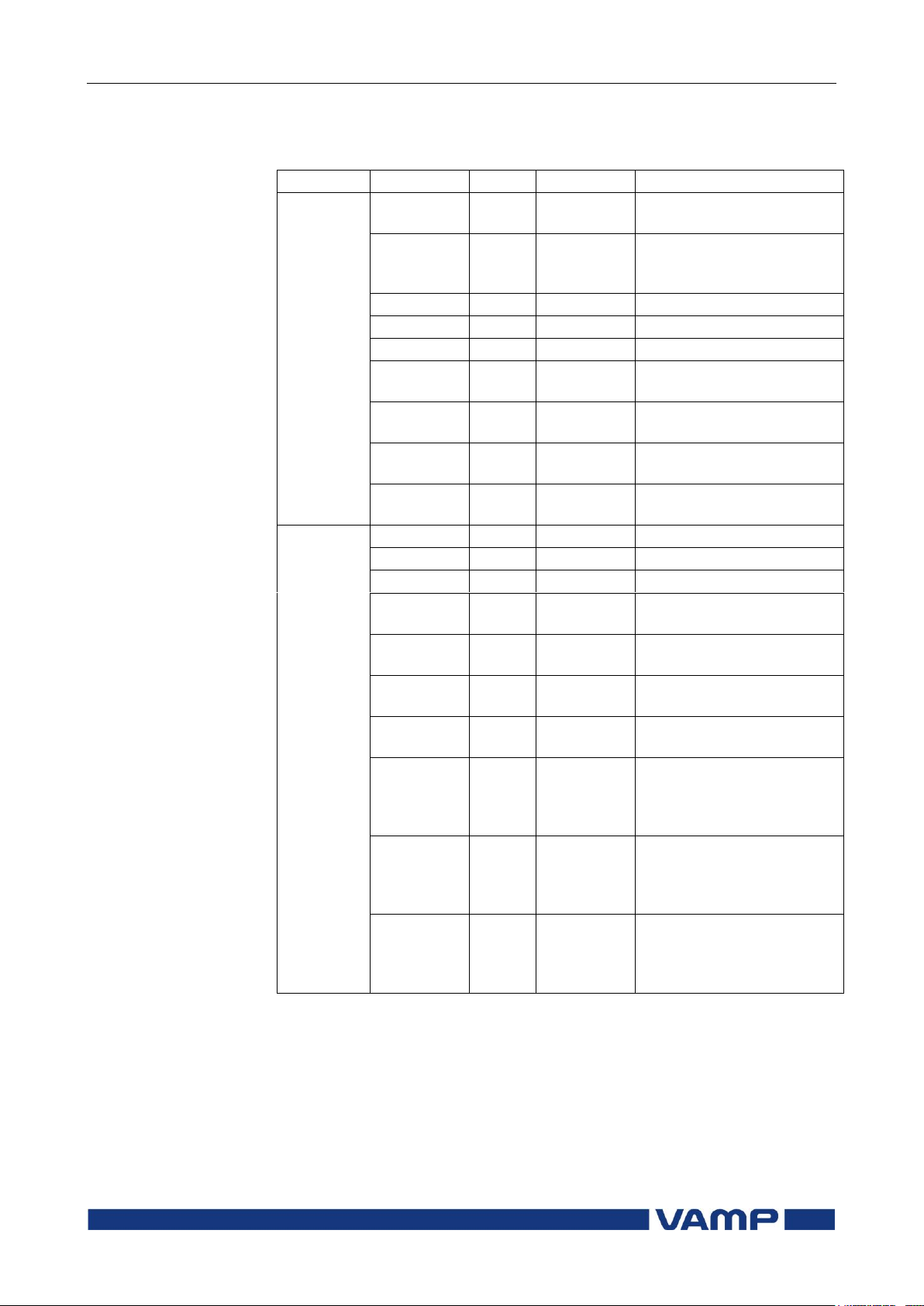
Technical description
2 Protection functions
2.10 Synchrocheck (25)
VM55.EN005
VAMP 24h support phone +358 (0)20 753 3264
71
Parameter
Values
Unit
Description
Measured
values
df - Hz
Measured frequency
difference
dU - % Un / deg
Measured voltage
amplitude and phase
angle difference
UState
-
-
Voltage status (e.g. DD)
SState
-
-
Synchrocheck status
ReqTime
-
-
Request time status
f
1)
-
Hz
Measured frequency
(reference side)
fy1) - Hz
Measured frequency
(comparison side)
U121)
-
% Un
Measured voltage
(reference side)
U12y1)
-
% Un
Measured voltage
(comparison side)
Recorded
values
ReqCntr
-
-
Request counter
SyncCntr
-
-
Synchronising counter
FailCntr
-
-
Fail counter
f1) - Hz
Recorded frequency
(reference side)
fy1) - Hz
Recorded frequency
(comparison side)
U121)
-
% Un
Recorded voltage
(reference side)
U12y1)
-
% Un
Recorded voltage
(comparison side)
dAng
-
Deg
Recorded phase angle
difference, when close
command is given from
the function
dAngC
-
Deg
Recorded phase angle
difference, when the
circuit-breaker actually
closes.
EDly
-
%
The elapsed time
compared to the set
request timeout setting,
100% = timeout
Measured and recorded values of synchrocheck stages
SyC1 (25):
1) Please note that the labels (parameter names) change according to the
voltage selection.
Page 72
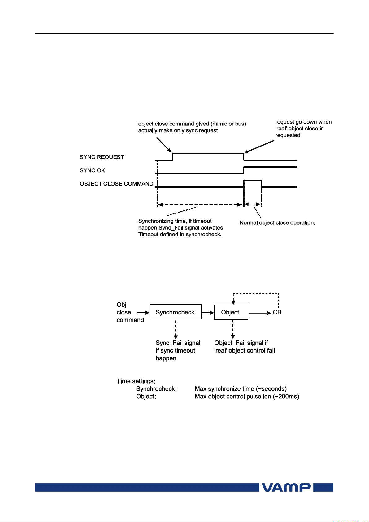
2.10 Synchrocheck (25)
2 Protection functions
Technical description
72
VAMP 24h support phone +358 (0)20 753 3264
VM55.EN005
The following signals of the stage are available in the output
matrix and the logic: “Request”, “OK” and “Fail”. The “request”signal is active, when a request has received but the breaker is
not yet closed. The “OK”-signal is active, when the
synchronising conditions are met, or the voltage check criterion
is met. The “fail”-signal is activated, if the function fails to close
the breaker within the request timeout setting. See below the
figure.
Figure 2.10-1 The principle of the synchrocheck function
Please note that the control pulse of the selected object should
be long enough. For example, if the voltages are in opposite
direction, the synchronising conditions are met after several
seconds.
Figure 2.10-2 The block diagram of the synchrocheck and the controlling
object
Please note that the wiring of the secondary circuits of voltage
transformers to the device terminal depends on the selected
voltage measuring mode.
Page 73

Technical description
2 Protection functions
2.10 Synchrocheck (25)
VM55.EN005
VAMP 24h support phone +358 (0)20 753 3264
73
Voltage
input
Terminals
Signals in mode
“3LN+LLy/LNy”
Ua
X1:1-5
U1
Ub
X1:2-5
U2
Uc
X1:3-5
U3
Ud
X1:4-5
U
12y/U1y
Number of synchrocheck stages
1
Availability of U0
No
Table 2.10-1 Voltage measurement modes for synchrocheck
function
The following application examples show the correct connection
of the voltage inputs. In the Figure 2.10-3 and Figure 2.10-4,
the applications require only one stage (Voltage measuring
modes are “3LN+LLy/LNy ”).
Page 74
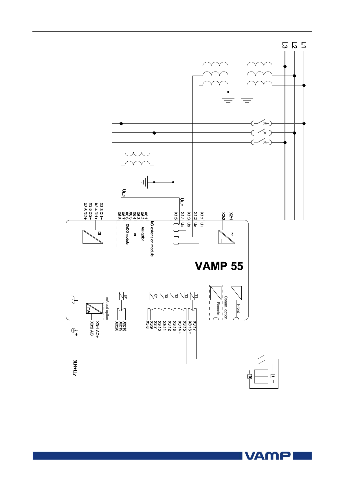
2.10 Synchrocheck (25)
2 Protection functions
Technical description
74
VAMP 24h support phone +358 (0)20 753 3264
VM55.EN005
* Voltage measurement of the 50-series relays should be at the same
potential with the grounding of the relay. Normally this happens
“automatically” on field but pay attention when doing tests with the
relay.
Figure 2.10-3 One synchrocheck stage with “3LN+LLy”-mode.
Page 75
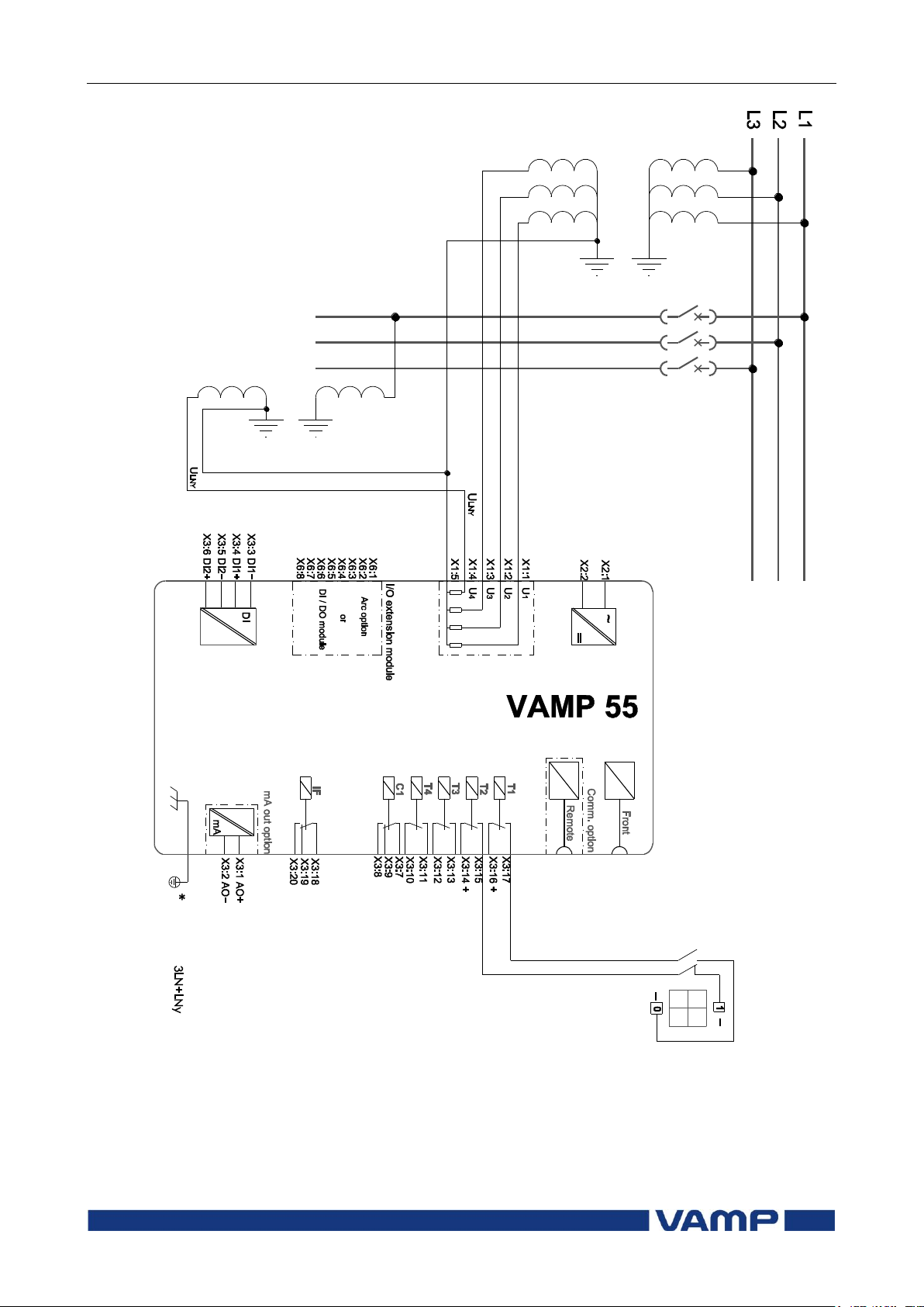
Technical description
2 Protection functions
2.10 Synchrocheck (25)
VM55.EN005
VAMP 24h support phone +358 (0)20 753 3264
75
* Voltage measurement of the 50-series relays should be at the same
potential with the grounding of the relay. Normally this happens
“automatically” on field but pay attention when doing tests with the
relay.
Figure 2.10-4 One synchrocheck stage with “3LN+LNy”-mode.
Page 76

2.11 Circuit breaker failure
protection CBFP (50BF)
2 Protection functions
Technical description
76
VAMP 24h support phone +358 (0)20 753 3264
VM55.EN005
Parameter
Value
Unit
Description
Note
Status
Blocked
Start
Trip
Current status of the stage
F
F
SCntr
Cumulative start counter
C
TCntr
Cumulative trip counter
C
Force
Off
On
Force flag for status forcing for
test purposes. This is a
common flag for all stages and
output relays, too.
Automatically reset by a 5minute timeout.
Set
Cbrelay
1 - 14
The supervised output relay.
Relay T1 – T14 (depending on
the orderinf code)
Set
t> s
Definite operation time.
Set
2.11. Circuit breaker failure protection CBFP
(50BF)
The circuit breaker failure protection can be used to trip any
upstream circuit breaker (CB), if the fault has not disappeared
within a given time after the initial trip command. A different
output contact of the device must be used for this backup trip.
The operation of the circuit-breaker failure protection (CBFP)
is based on the supervision of the signal to the selected trip
relay and the time the fault remains on after the trip command.
If this time is longer than the operating time of the CBFP
stage, the CBFP stage activates another output relay, which
will remain activated until the primary trip relay resets.
The CBFP stage is supervising all the protection stages using
the same selected trip relay, since it supervises the control
signal of this device. See chapter 5.5 for details about the
output matrix and the trip relays.
Parameters of the circuit breaker failure stage CBFP (50BF)
For details of setting ranges see chapter 9.3.
Set = An editable parameter (password needed)
C = Can be cleared to zero
F = Editable when force flag is on
Recorded values of the latest eight faults
There are detailed information available of the eight latest
faults: Time stamp and elapsed delay.
Page 77

Technical description
2 Protection functions
2.11 Circuit breaker failure
protection CBFP (50BF)
VM55.EN005
VAMP 24h support phone +358 (0)20 753 3264
77
Parameter
Value
Unit
Description
yyyy-mm-dd
Time stamp of the recording, date
hh:mm:ss.ms
Time stamp, time of day
EDly %
Elapsed time of the operating time
setting. 100% = trip
Recorded values of the circuit breaker failure stage (8 latest
faults) CBFP (50BF)
Page 78

2.12 Programmable stages (99)
2 Protection functions
Technical description
78
VAMP 24h support phone +358 (0)20 753 3264
VM55.EN005
Priority
If operation times less than 60 milliseconds are needed
select 10 ms. For operation times under one second 20 ms
is recommended. For longer operation times and THD
signals 100 ms is recommended.
Link
The name of the supervised signal (see table below).
Cmp
Compare mode. „>‟ for over or „<‟ for under comparison.
Pick-up
Limit of the stage. The available setting range and the unit
depend on the selected signal.
T
Definite time operation delay
Hyster
Dead band (hysteresis)
NoCmp
Only used with compare mode under („<‟). This is the limit
to start the comparison. Signal values under NoCmp are
not regarded as fault.
2.12. Programmable stages (99)
For special applications the user can built his own protection
stages by selecting the supervised signal and the comparison
mode.
The following parameters are available:
Page 79
Technical description
2 Protection functions
2.12 Programmable stages (99)
VM55.EN005
VAMP 24h support phone +358 (0)20 753 3264
79
U12, U23, U31
Line-to-line voltages
UL1, UL2, UL3
Phase-to-ground voltages
Uo
Zero-sequence voltage
f
Frequency
THDUa
Total harmonic distortion of input Ua
THDUb
Total harmonic distortion of input Ub
THDUc
Total harmonic distortion of input Uc
fy
Frequency behind circuit breaker
U12y
Voltage behind circuit breaker
U12z
Voltage behind 2nd circuit breaker
ULLmin,
ULLmax
Minimum and maximum of line voltages
ULNmin,
ULNmax
Minimum and maximum of phase
voltages
Table 2.12-1Available signals to be supervised by the programmable stages
Eight independent stages
The device has eight independent programmable stages. Each
programmable stage can be enabled or disabled to fit the
intended application.
Setting groups
There are two settings groups available. Switching between
setting groups can be controlled by digital inputs, virtual
inputs (communication, logic) and manually.
There are two identical stages available with independent
setting parameters.
Page 80
2.12 Programmable stages (99)
2 Protection functions
Technical description
80
VAMP 24h support phone +358 (0)20 753 3264
VM55.EN005
Parameter
Value
Unit
Description
Note
Status
Blocked
Start
Trip
Current status of the stage
F
F
SCntr
Cumulative start counter
C
TCntr
Cumulative trip counter
C
SetGrp
1 or 2
Active setting group
Set
SgrpDI
-
Dix
Vix
LEDx
Vox
Fx
Digital signal to select the
active setting group
None
Digital input
Virtual input
LED indicator signal
Virtual output
Function key
Set
Force
Off
On
Force flag for status forcing
for test purposes. This is a
common flag for all stages and
output relays, too.
Automatically reset by a 5minute timeout.
Set
Link
(See
Table
2.12-1)
Name for the supervised
signal
Set
(See Table
2.12-1)
Value of the supervised signal
Cmp
>
<
Mode of comparison
Over protection
Under protection
Set
Pickup
Pick up value scaled to
primary level
Pickup
pu
Pick up setting in pu
Set
t s
Definite operation time.
Set
Hyster
% Dead band setting
Set
NoCmp
pu
Minimum value to start under
comparison. (Mode=‟<‟)
Set
Parameters of the programmable stages PrgN (99)
Set = An editable parameter (password needed)
C = Can be cleared to zero
F = Editable when force flag is on
Recorded values of the latest eight faults
There is detailed information available of the eight latest
faults: Time stamp, fault value and elapsed delay.
Page 81

Technical description
2 Protection functions
2.12 Programmable stages (99)
VM55.EN005
VAMP 24h support phone +358 (0)20 753 3264
81
Parameter
Value
Unit
Description
yyyy-mm-dd
Time stamp of the recording, date
hh:mm:ss.ms
Time stamp, time of day
Flt pu
Fault value
Edly %
Elapsed time of the operating time
setting. 100% = trip
SetGrp
1
2
Active setting group during fault
Recorded values of the programmable stages PrgN (99)
Page 82
3.1 Event log
3 Supporting functions
Technical description
82
VAMP 24h support phone +358 (0)20 753 3264
VM55.EN005
EVENT
Description
Local
panel
Communication
protocols
Code: 30E2
Channel 30,
event 2
Yes
Yes
U> trip on
Event text
Yes
No
120 Un%
Fault value
Yes
No
2007-01-31
Date
Yes
Yes
08:35:13.413
Time
Yes
Yes
Type: 1-N, 2-N, 3-N
Fault type
Yes
No
3. Supporting functions
3.1. Event log
Event log is a buffer of event codes and time stamps including
date and time. For example each start-on, start-off, trip-on or
trip-off of any protection stage has a unique event number code.
Such a code and the corresponding time stamp is called an
event. The event codes are listed in a separate document
“Modbus_Profibus_Spabus_event.pdf”.
As an example of information included with a typical event an
overvoltage trip event of the first 59 stage U> is shown in the
following table.
Events are the major data for a SCADA system. SCADA
systems are reading events using any of the available
communication protocols. Event log can also be scanned using
the front panel or using VAMPSET. With VAMSET the events
can be stored to a file especially in case the relay is not
connected to any SCADA system.
Only the latest event can be read when using communication
protocols or VAMPSET. Every reading increments the internal
read pointer to the event buffer. (In case of communication
error, the latest event can be reread any number of times using
an other parameter.) On the local panel scanning the event
buffer back and forth is possible.
Event enabling/masking
In case of an uninteresting event, it can be masked, which
prevents the particular event(s) to be written in the event
buffer.
As a default there is room for 200 latest events in the buffer.
Event buffer size can be modified from 50 to 2000 in all v.10.xx
softwares. Modification can be done in “Local panel conf” –
menu. Alarm screen (popup screen) can also be enabled in this
same menu when Vampset –setting tool is used. The oldest one
Page 83
Technical description
3 Supporting functions
3.1 Event log
VM55.EN005
VAMP 24h support phone +358 (0)20 753 3264
83
Parameter
Value
Description
Note
Count
Number of events
ClrEn
Clear
Clear event buffer
Set
Order
Old-
New
New-
Old
Order of the event buffer for local
display
Set
FVSca
PU
Pri
Scaling of event fault value
Per unit scaling
Primary scaling
Set
Display
Alarms
On
Off
Alarm pop-up display is enabled
No alarm display
Set
FORMAT OF EVENTS ON THE LOCAL DISPLAY
Code: CHENN
CH = event channel, NN=event code
Event description
Event channel and code in plain text
yyyy-mm-dd
Date (for available date formats see chapter 3.6)
hh:mm:ss.nnn
Time
will be overwritten, when a new event does occur. The shown
resolution of a time stamp is one millisecond, but the actual
resolution depends of the particular function creating the
event. For example most protection stages create events with
10 ms or 20 ms resolution. The absolute accuracy of all time
stamps depends on the time synchronizing of the relay. See
chapter 3.6 for system clock synchronizing.
Event buffer overflow
The normal procedure is to poll events from the device all the
time. If this is not done, the event buffer will eventually
overflow. On the local screen this is indicated with string
“OVF” after the event code.
Setting parameters for events
Page 84

3.2 Disturbance recorder
3 Supporting functions
Technical description
84
VAMP 24h support phone +358 (0)20 753 3264
VM55.EN005
3.2. Disturbance recorder
The disturbance recorder can be used to record all the
measured signals, that is, currents, voltages and the status
information of digital inputs (DI) and digital outputs (DO). The
digital inputs include also the arc protection signals S1, S2, BI
and BO, if the optional arc protection is available.
Triggering the recorder
The recorder can be triggered by any start or trip signal from
any protection stage or by a digital input. The triggering signal
is selected in the output matrix (vertical signal DR). The
recording can also be triggered manually. All recordings are
time stamped.
Reading recordings
The recordings can be uploaded, viewed and analysed with the
VAMPSET program. The recording is in COMTRADE format.
This means that also other programs can be used to view and
analyse the recordings made by the relay.
For more details, please see a separate VAMPSET manual.
Number of channels
At the maximum, there can be 12 recordings, and the
maximum selection of channels in one recording is also 12
(limited in waveform recording). The digital inputs reserve one
channel (includes all the inputs). Also the digital outputs
reserve one channel (includes all the outputs). If digital inputs
and outputs are recorded, there will be still 10 channels left for
analogue waveforms.
Page 85

Technical description
3 Supporting functions
3.2 Disturbance recorder
VM55.EN005
VAMP 24h support phone +358 (0)20 753 3264
85
Parameter
Value
Unit
Description
Note
Mode
Saturated
Overflow
Behaviour in memory full
situation:
No more recordings are
accepted
The oldest recorder will be
overwritten
Set
SR
32/cycle
16/cycle
8/cycle
1/10ms
1/20ms
1/200ms
1/1s
1/5s
1/10s
1/15s
1/30s
1/1min
Sample rate
Waveform
Waveform
Waveform
One cycle value *)
One cycle value
**)
Average
Average
Average
Average
Average
Average
Average
Set
Time s
Recording length
Set
PreTrig
% Amount of recording data
before the trig moment
Set
MaxLen
s Maximum time setting.
This value depends on
sample rate, number and
type of the selected
channels and the
configured recording
length.
Status
Run
Trig
FULL
Status of recording
Not active
Waiting a triggering
Recording
Memory is full in saturated
mode
ManTrig
Trig
Manual triggering
Set
ReadyRec
n/m
n = Available recordings
m = maximum number of
recordings
The value of „m‟ depends on
sample rate, number and
type of the selected
channels and the
configured recording
length.
Disturbance recorder parameters
Page 86
3.2 Disturbance recorder
3 Supporting functions
Technical description
86
VAMP 24h support phone +358 (0)20 753 3264
VM55.EN005
Parameter
Value
Unit
Description
Note
AddCh
Add one channel.
Maximum simultaneous
number of channels is 12.
Set
U12, U23,
U31
Line-to-line voltage
UL1, UL2,
UL3
Phase-to-neutral voltage
Uo Zero sequence voltage
f Frequency
DO
Digital outputs
DI Digital inputs
U1 Positive sequence voltage
U2 Negative sequence voltage
U2/U1
Relative voltage unbalance
Uphase
Average (UL1 + UL2 +
UL3)/3
Uline
Average (U12 + U23 +
U31)/3
THDUa
Total harmonic distortion
of input Ua
THDUb
Total harmonic distortion
of input Ub
THDUc
Total harmonic distortion
of input Uc
fy Frequency behind circuit
breaker
fz Frequency behind 2nd
circuit breaker
U12y ***
Voltage behind circuit
breaker
AddCh
ULLmin ***
Minimum of line voltages
ULLmax ***
Maximum of line voltages
ULNmin ***
Minimum of phase voltages
ULNmax
***
Maximum of phase voltages
ClrCh
Clear
Remove all channels
Set
(Ch)
List of selected channels
Set = An editable parameter (password needed)
*) This is the fundamental frequency rms value of one cycle updated every
10 ms.
**) This is the fundamental frequency rms value of one cycle updated every
20 ms.
Page 87
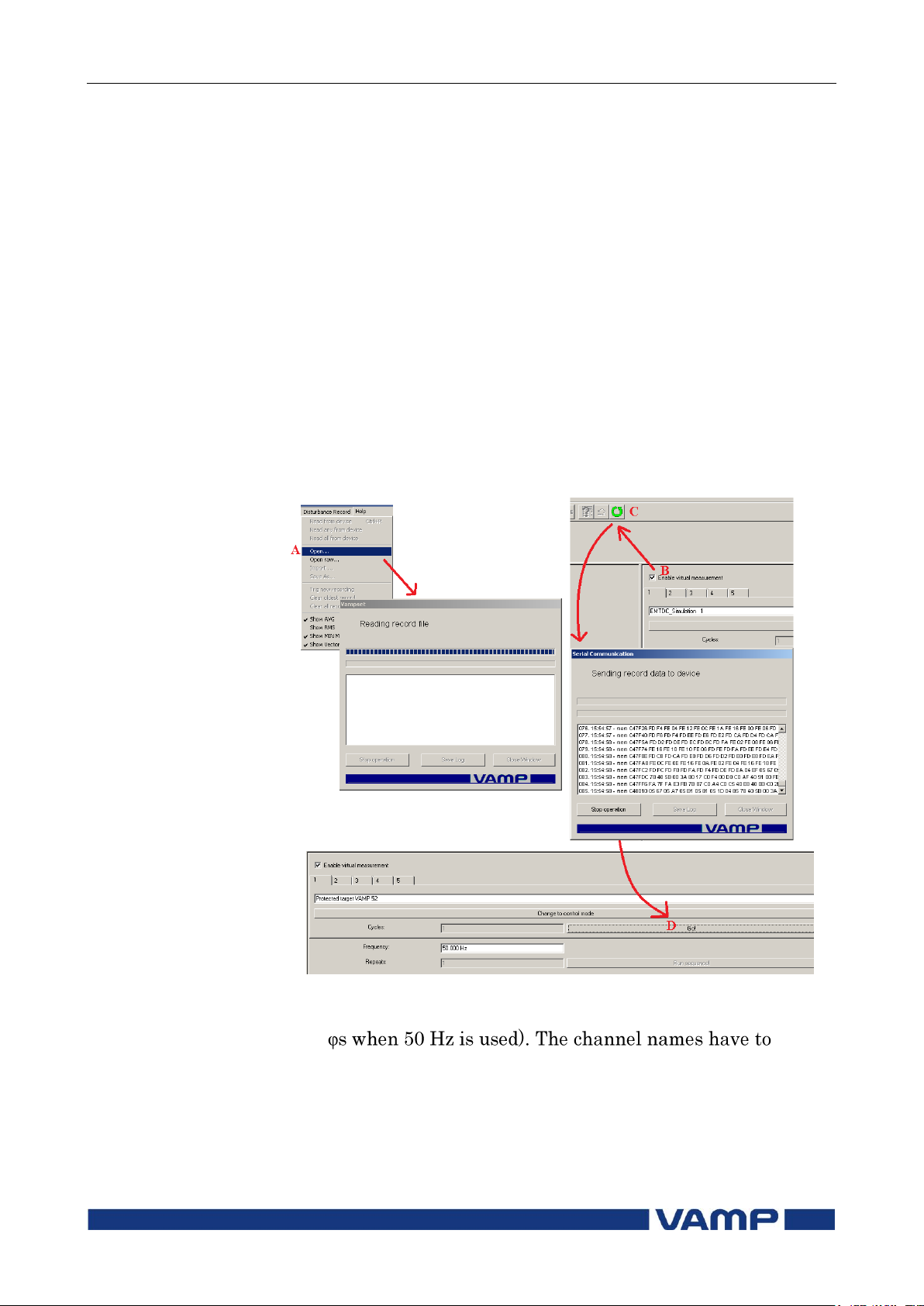
Technical description
3 Supporting functions
3.2 Disturbance recorder
VM55.EN005
VAMP 24h support phone +358 (0)20 753 3264
87
Running virtual comtrade files with VAMP relays
Virtual comtrade files can be run with VAMP relays with the
v.10.74 software or a later version. Relay behaviour can be
analysed by playing the recorder data over and over again in
the relay memory.
Steps of opening the VAMPSET setting tool.
1. Go to “Disturbance record” and select Open… (A).
2. Select the comtrade file from you hard disc or equivalent.
VAMPSET is now ready to read the recording.
3. The virtual measurement has to be enabled (B) in order to
send record data to the relay (C).
4. Sending the file to the relay‟s memory takes a few seconds.
Initiate playback of the file by pressing the Go! button (D).
The “Change to control mode” button takes you back to the
virtual measurement.
Note! The sample rate of the comtrade file has to be 32/cycle
(625
correspond to the channel names in Vamp relays: IL1, IL2, IL3,
Io1, Io2, U12, U23, UL1, UL2, UL3 and Uo.
Page 88
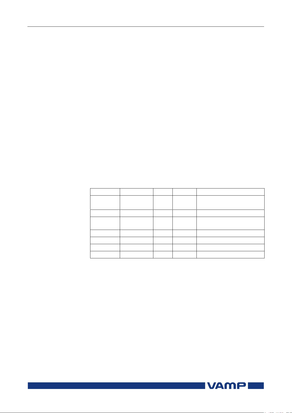
3.3 Voltage sags and swells
3 Supporting functions
Technical description
88
VAMP 24h support phone +358 (0)20 753 3264
VM55.EN005
Parameter
Value
Unit
Default
Description
U>
20 … 150
%
110
Setting value of swell limit
U<
10 … 120
%
90
Setting value of sag limit
Delay
0.04 … 1.00
s
0.06
Delay for sag and swell
detection
SagOn
On; Off
-
On
Sag on event
SagOff
On; Off
-
On
Sag off event
SwelOn
On; Off
-
On
Swell on event
SwelOf
On; Off
-
On
Swell off event
3.3. Voltage sags and swells
VS_SagSwell The power quality of electrical networks has become
increasingly important. The sophisticated loads (e.g. computers
etc.) require uninterruptible supply of “clean” electricity. VAMP
protection platform provides many power quality functions that
can be used to evaluate, monitor and alarm on the basis of the
quality. One of the most important power quality functions are
voltage sag and swell monitoring.
VAMP provides separate monitoring logs for sags and swells.
The voltage log is trigged, if any voltage input either goes
under the sag limit (U<) or exceeds the swell limit (U>). There
are four registers for both sags and swells in the fault log. Each
register will have start time, phase information, duration,
minimum, average, maximum voltage values of each sag and
swell event. Furthermore, there are total number of sags and
swells counters as well as total timers for sags and swells.
The voltage power quality functions are located under the
submenu “U”.
Setting parameters of sags and swells monitoring:
Page 89
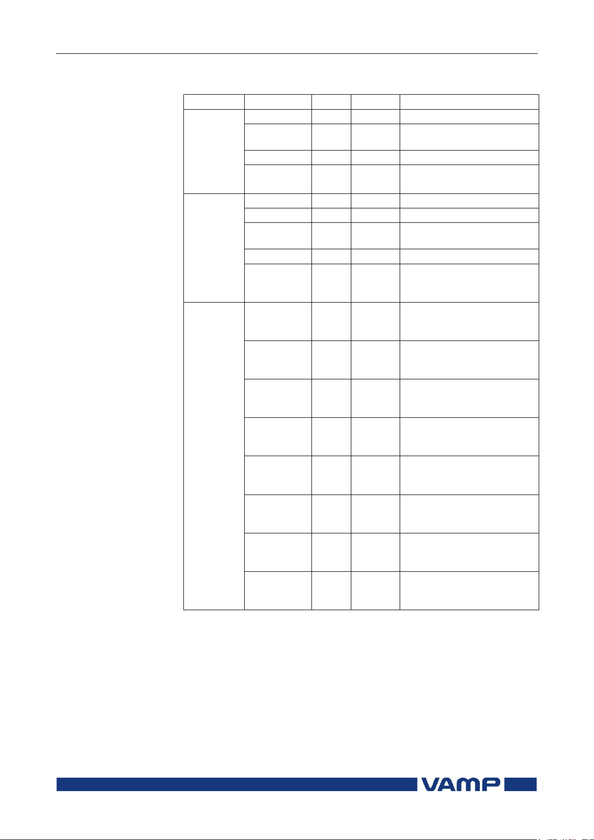
Technical description
3 Supporting functions
3.3 Voltage sags and swells
VM55.EN005
VAMP 24h support phone +358 (0)20 753 3264
89
Parameter
Value
Unit
Description
Recorded
values
Count -
Cumulative sag counter
Total -
Cumulative sag time
counter
Count -
Cumulative swell counter
Total -
Cumulative swell time
counter
Sag/ swell
logs 1…4
Date -
Date of the sag/swell
Time -
Time stamp of the sag/swell
Type -
Voltage inputs that had the
sag/swell
Time s
Duration of the sag/swell
Min1 %Un
Minimum voltage value
during the sag/swell in the
input 1
Min2 %Un
Minimum voltage value
during the sag/swell in the
input 2
Min3 %Un
Minimum voltage value
during the sag/swell in the
input 3
Ave1 %Un
Average voltage value
during the sag/swell in the
input 1
Ave2 %Un
Average voltage value
during the sag/swell in the
input 2
Ave3 %Un
Average voltage value
during the sag/swell in the
input 3
Max1
%Un
Maximum voltage value
during the sag/swell in the
input 1
Max2
%Un
Maximum voltage value
during the sag/swell in the
input 2
Max3
%Un
Maximum voltage value
during the sag/swell in the
input 3
Recorded values of sags and swells monitoring:
For details of setting ranges see chapter 9.4.2.
Page 90
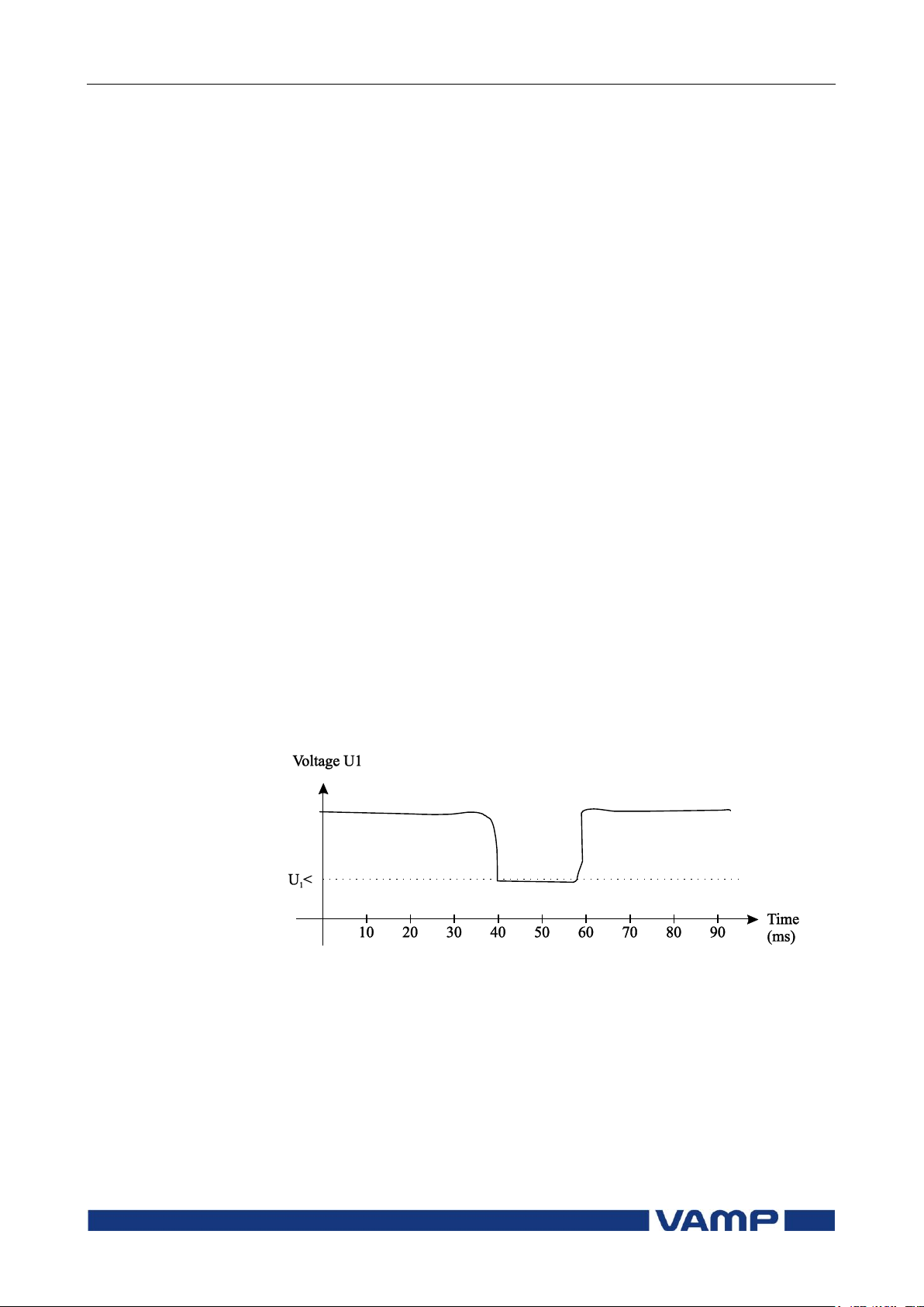
3.4 Voltage interruptions
3 Supporting functions
Technical description
90
VAMP 24h support phone +358 (0)20 753 3264
VM55.EN005
3.4. Voltage interruptions
VS_VoltageInts The device includes a simple function to detect voltage
interruptions. The function calculates the number of voltage
interruptions and the total time of the voltage-off time within a
given calendar period. The period is based on the real time
clock of the device. The available periods are:
8 hours, 00:00 – 08:00, 08:00 – 16:00, 16:00 – 24:00
one day, 00:00 – 24:00
one week, Monday 00:00 – Sunday 24:00
one month, the first day 00:00 – the last day 24:00
one year, 1st January 00:00 – 31st December 24:00
After each period, the number of interruptions and the total
interruption time are stored as previous values. The
interruption counter and the total time are cleared for a new
period. The old previous values are overwritten.
The voltage interruption is based on the value of the positive
sequence voltage U1 and a user given limit value. Whenever
the measured U1 goes below the limit, the interruption counter
is increased, and the total time counter starts increasing.
Shortest recognized interruption time is 40 ms. If the voltageoff time is shorter it may be recognized depending on the
relative depth of the voltage dip.
If the voltage has been significantly over the limit U1< and then
there is a small and short under-swing, it will not be recognized
(Figure 3.4-1).
Figure 3.4-1. A short voltage interruption which is probably not recognized
On the other hand, if the limit U1< is high and the voltage has
been near this limit, and then there is a short but very deep
dip, it will be recognized (Figure 3.4-2).
Page 91
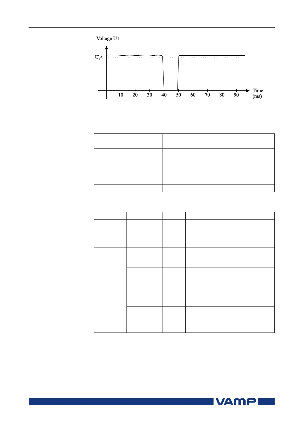
Technical description
3 Supporting functions
3.4 Voltage interruptions
VM55.EN005
VAMP 24h support phone +358 (0)20 753 3264
91
Parameter
Value
Unit
Default
Description
U1<
10.0 … 120.0
%
64
Setting value
Period
8h
Day
Week
Month
-
Month
Length of the observation
period
Date - - Date
Time - - Time
Parameter
Value
Unit
Description
Measured
value
Voltage
LOW;
OK
-
Current voltage status
U1 %
Measured positive
sequence voltage
Recorded
values
Count -
Number of voltage sags
during the current
observation period
Prev -
Number of voltage sags
during the previous
observation period
Total s
Total (summed) time of
voltage sags during the
current observation period
Prev s
Total (summed) time of
voltage sags during the
previous observation
period
Figure 3.4-2 A short voltage interrupt that will be recognized
Setting parameters of the voltage sag measurement
function:
Measured and recorded values of voltage sag measurement
function:
For details of setting ranges see chapter 9.4.3.
Page 92
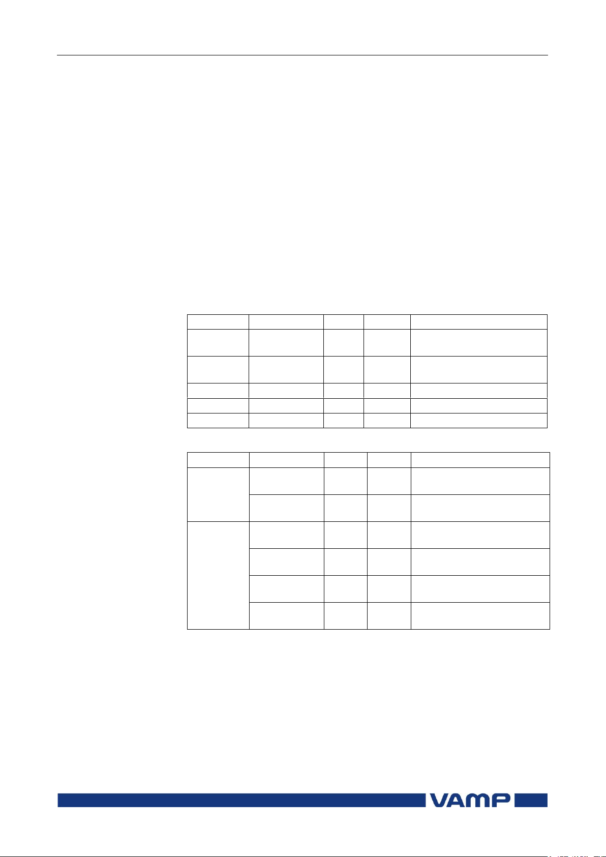
3.5 Voltage transformer supervision
3 Supporting functions
Technical description
92
VAMP 24h support phone +358 (0)20 753 3264
VM55.EN005
Parameter
Value
Unit
Default
Description
U2>
0.0 … 200.0
%Un
34.6
Upper setting for VT
supervisor
I2<
0.0 … 200.0
%In
100.0
Lower setting for VT
supervisor
t>
0.02 … 600.0
s
0.10
Operation delay
VT on
On; Off
-
On
VT supervisor on event
VT off
On; Off
-
On
VT supervisor off event
Parameter
Value
Unit
Description
Measured
value
U2 %Un
Measured negative
sequence voltage
I2 %In
Measured negative
sequence current
Recorded
Values
Date -
Date of VT supervision
alarm
Time -
Time of VT supervision
alarm
U2 %Un
Recorded negative
sequence voltage
I2 %In
Recorded negative
sequence current
3.5. Voltage transformer supervision
The device supervises the VTs and VT wiring between the
device terminals and the VTs. If there is a fuse in the voltage
transformer circuitry, the blown fuse prevents or distorts the
voltage measurement. Therefore, an alarm should be issued.
Furthermore, in some applications, protection functions using
voltage signals, should be blocked to avoid false tripping.
The VT supervisor function measures the three phase voltages
and currents. The negative sequence voltage U2 and the
negative sequence currentI2 are calculated. If U2 exceed the
U2> setting and at the same time, I2 is less than the I2< setting,
the function will issue an alarm after the operation delay has
elapsed.
Setting parameters of VT supervisor VTSV ( ):
Measured and recorded values of VT supervisor VTSV ( ):
Page 93

Technical description
3 Supporting functions
3.6 System clock and
synchronization
VM55.EN005
VAMP 24h support phone +358 (0)20 753 3264
93
WeekDriftInOne
AAIntv
8.604
8.604
1
1
WeekDriftInOne
AAIntv
AAIntv
PREVIOUS
NEW
3.6. System clock and synchronization
The internal clock of the relay is used to time stamp events and
disturbance recordings.
The system clock should be externally synchronised to get
comparable event time stamps for all the relays in the system.
The synchronizing is based on the difference of the internal
time and the synchronising message or pulse. This deviation is
filtered and the internal time is corrected softly towards a zero
deviation.
Adapting auto adjust
During tens of hours of synchronizing the device will learn its
average error and starts to make small corrections by itself.
The target is that when the next synchronizing message is
received, the deviation is already near zero. Parameters
"AAIntv" and "AvDrft" will show the adapted correction time
interval of this 1 ms auto-adjust function.
Time drift correction without external sync
If any external synchronizing source is not available and the
system clock has a known steady drift, it is possible to roughly
correct the clock error by editing the parameters "AAIntv" and
"AvDrft". The following equation can be used if the previous
"AAIntv" value has been zero.
If the auto-adjust interval "AAIntv" has not been zero, but
further trimming is still needed, the following equation can be
used to calculate a new auto-adjust interval.
The term
DriftInOneWeek
/604.8 may be replaced with the
relative drift multiplied by 1000, if some other period than one
week has been used. For example if the drift has been 37
seconds in 14 days, the relative drift is 37*1000/(14*24*3600) =
0.0306 ms/s.
Page 94

3.6 System clock and
synchronization
3 Supporting functions
Technical description
94
VAMP 24h support phone +358 (0)20 753 3264
VM55.EN005
sAAIntv
LeadAvDrft
9.9
61
8.604
6.10
3600249
5000
9.9
1
1
NEW
AAIntv
LeadAvDrft
Parameter
Value
Unit
Description
Note
Date
Current date
Set
Time
Current time
Set
Style
ydm
d.m.y
m/d/y
Date format
Year-Month-Day
Day.Month.Year
Month/Day/Year
Set
SyncDI
DI1, DI2
The digital input used for
clock synchronisation.
DI not used for synchronizing
Minute pulse input
***)
TZone
12.00 ...
+14.00 *)
UTC time zone for SNTP
synchronization.
Note: This is a decimal
number. For example for state
of Nepal the time zone 5:45 is
given as 5.75
Set
DST
No
Yes
Daylight saving time for
SNTP
Set
Example 1.
If there has been no external sync and the relay's clock is
leading sixty-one seconds a week and the parameter AAIntv
has been zero, the parameters are set as
With these parameter values the system clock corrects itself
with –1 ms every 9.9 seconds which equals 61.091 s/week.
Example 2.
If there is no external sync and the relay's clock has been
lagging five seconds in nine days and the AAIntv has been
9.9 s, leading, then the parameters are set as
NOTE! When the internal time is roughly correct – deviation is less than four
seconds – any synchronizing or auto-adjust will never turn the clock
backwards. Instead, in case the clock is leading, it is softly slowed down
to maintain causality.
System clock parameters
Page 95
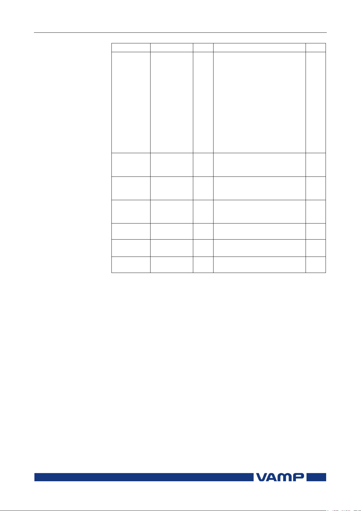
Technical description
3 Supporting functions
3.6 System clock and
synchronization
VM55.EN005
VAMP 24h support phone +358 (0)20 753 3264
95
Parameter
Value
Unit
Description
Note
SySrc
Internal
DI
SNTP
SpaBus
ModBus
ProfibusDP
IEC-103
IEC101
DNP3
IRIG-B003
Clock synchronisation source
No sync recognized since 200s
Digital input
Protocol sync
Protocol sync
Protocol sync
Protocol sync
Protocol sync
Protocol sync
Protocol sync
IRIG timecode B003
****)
MsgCnt
0 ... 65535, 0
... etc.
The number of received
synchronisation messages or
pulses
Dev
32767
ms
Latest time deviation between
the system clock and the
received synchronization
SyOS
10000.000
s
Synchronisation correction for
any constant error in the
synchronizing source.
Set
AAIntv
10000
s
Adapted auto adjust interval
for 1 ms correction
Set
**
)
AvDrft
Lead
Lag
Adapted average clock drift
sign
Set
**)
FilDev
125
ms
Filtered synchronisation
deviation
Set = An editable parameter (password needed).
*) Astronomically a range –11 ... +12 h would be enough, but for political
and geographical reasons a larger range is needed.
**) If external synchronization is used this parameter will be set
automatically.
***) Set the DI delay to its minimum and the polarity such that the leading
edge is the synchronizing edge.
****) Relay needs to be equipped with an IRIG-B option module to receive
clock syncronization signal (see chapter 12 for more information).
Synchronisation with DI
Clock can be synchronized by reading minute pulses from
digital inputs, virtual inputs or virtual outputs. Sync source is
selected with SyncDI setting. When rising edge is detected from
the selected input, system clock is adjusted to the nearest
minute. Length of digital input pulse should be at least 50 ms.
Delay of the selected digital input should be set to zero.
Page 96

3.6 System clock and
synchronization
3 Supporting functions
Technical description
96
VAMP 24h support phone +358 (0)20 753 3264
VM55.EN005
Synchronisation correction
If the sync source has a known offset delay, it can be
compensated with SyOS setting. This is useful for
compensating hardware delays or transfer delays of
communication protocols. A positive value will compensate a
lagging external sync and communication delays. A negative
value will compensate any leading offset of the external synch
source.
Sync source
When the device receives new sync message, the sync source
display is updated. If no new sync messages are received within
next 1.5 minutes, the device will change to internal sync mode.
Deviation
The time deviation means how much system clock time differs
from sync source time. Time deviation is calculated after
receiving new sync message. The filtered deviation means how
much the system clock was really adjusted. Filtering takes care
of small errors in sync messages.
Auto-lag/lead
The device synchronizes to the sync source, meaning it starts
automatically leading or lagging to stay in perfect sync with the
master. The learning process takes few days.
Page 97

Technical description
3 Supporting functions
3.7 Self-supervision
VM55.EN005
VAMP 24h support phone +358 (0)20 753 3264
97
3.7. Self-supervision
The functions of the microcontroller and the associated
circuitry, as well as the program execution are supervised by
means of a separate watchdog circuit. Besides supervising the
relay, the watchdog circuit attempts to restart the micro
controller in a fault situation. If the restarting fails, the
watchdog issues a self-supervision alarm indicating a
permanent internal fault.
When the watchdog circuit detects a permanent fault, it always
blocks any control of other output relays (except for the selfsupervision output relay).
In addition, the internal supply voltages are supervised. Should
the auxiliary supply of the relay disappear, an alarm is
automatically given because the internal fault (IF) output relay
functions on a working current principle. This means that the
IF relay is energized when the auxiliary supply is on and no
internal fault is detected.
3.7.1. Diagnostics
The device runs self-diagnostic tests for hardware and software
in every boot sequence and also performs runtime checking.
Fatal errors
If fatal error has been detected, the device releases IF relay
contact and error led is set on. Local panel will also display an
error message about the detected fault. Fatal error state is
entered when the device is not able to handle protections.
Runtime errors
When self-diagnostic function detects a fault, Selfdiag Alarm
matrix signal is set and an event (E56) is generated. In case the
error was only temporary, an off event is generated (E57). Self
diagnostic error can be reset via local panel interface.
Error registers
There are four 16-bit error registers which are readable
through remote protocols. The following table shows the
meaning of each error register and their bits.
Page 98
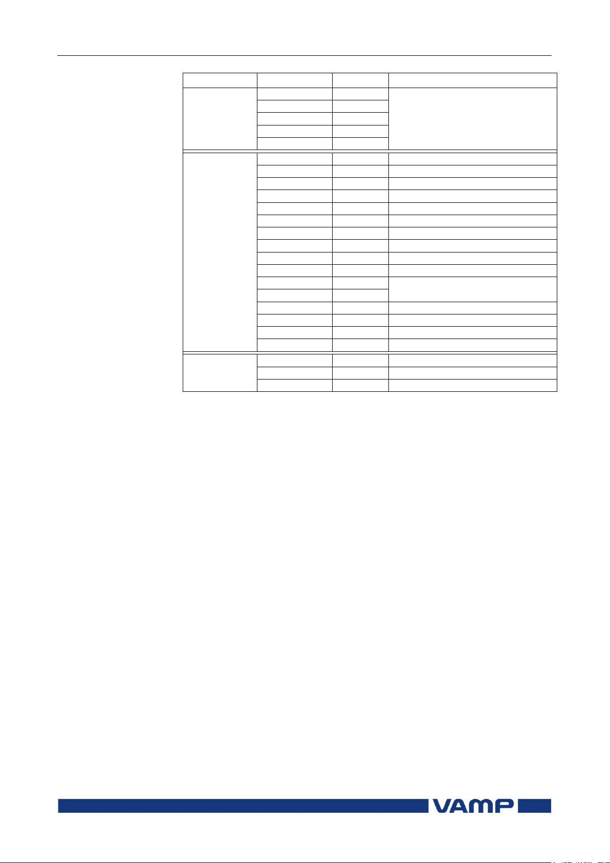
3.7 Self-supervision
3 Supporting functions
Technical description
98
VAMP 24h support phone +358 (0)20 753 3264
VM55.EN005
Register
Bit
Code
Description
SelfDiag1
0 (LSB)
T1
Output relay fault
1
T2 2 T3 3 T4 4 A1
SelfDiag3
0 (LSB)
DAC
mA-output fault
1
STACK
OS: stack fault
2
MemChk
OS: memory fault
3
BGTask
OS: background task timeout
4
DI
Digital input fault (DI1, DI2)
5
6
Arc
Arc card fault
7
SecPulse
Hardware error
8
RangeChk
DB: Setting outside range
9
CPULoad
OS: overload
10
+24V
Internal voltage fault
11
-15V
12
ITemp
Internal temperature too high
13
ADChk1
A/D converter error
14
ADChk2
A/D converter error
15 (MSB)
E2prom
E2prom error
SelfDiag4
0 (LSB)
+12V
Internal voltage fault
1
ComBuff
BUS: buffer error
2
OrderCode
Order code error
The error code is displayed in self diagnostic events and on the
diagnostic menu on local panel and VAMPSET.
Page 99
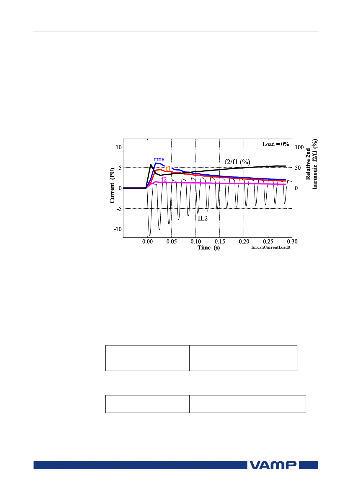
Technical description
4 Measurement functions
4.1 Measurement accuracy
VM55.EN005
VAMP 24h support phone +358 (0)20 753 3264
99
Measuring range L- N
0 – 300 V
(LL measurement 0 – 520 V)
Inaccuracy
0.5 % or 0.3 V
Measuring range
16 Hz – 75 Hz
Inaccuracy
10 mHz
4. Measurement functions
All the direct measurements are based on fundamental
frequency values. The exception is frequency. Most protection
functions are also based on the fundamental frequency values.
The figure shows a current waveform and the corresponding
fundamental frequency component f1, second harmonic f2 and
rms value in a special case, when the current deviates
significantly from a pure sine wave.
Figure 4-1 Example of various current values of a transformer inrush
current.
4.1. Measurement accuracy
Voltage inputs UA, UB, U
The usage of voltage inputs depends on the configuration
parameter “voltage measurement mode”. For example, Ud is
the zero sequence voltage input U0 if the mode “3LL + U0” is
selected.
The specified frequency range is 45 Hz – 65 Hz.
Frequency
The frequency is measured from current signals.
C, UD
Page 100

4.2 Minimum and maximum values
4 Measurement functions
Technical description
100
VAMP 24h support phone +358 (0)20 753 3264
VM55.EN005
Min & Max
measurement
Description
U12, U23, U31
Line-to-line voltage
Uo
Zero sequence voltage
f
Frequency
Parameter
Value
Description
Set
ClrMax
Clear
Reset all minimum and maximum
values
S
4.2. Minimum and maximum values
Minimum and maximum values are registered with time
stamps since the latest manual clearing or since the device has
been restarted. The available registered min & max values are
listed in the following table.
The clearing parameter "ClrMax" is common for all these
values.
Parameters
4.3. Voltage measurement modes
Depending on the application and available voltage
transformers, the relay can be connected either to line-to-line
voltages or phase-to-ground voltages. The configuration
parameter "Voltage measurement mode" must be set according
the used connection.
The available modes are:
“3LN+LLy/LNy”
This mode is used with the synchrocheck function. See Table
2.10-1.
“3LN+Uo”
The device is connected to line-to-netural voltages U
to zero sequence voltage U0. The phase-to-phase voltages are
calculated. See Figure 8.7-3.
- UL3 and
L1
The overvoltage protection is always based on the line-to-line
voltage regardless of the measurement mode.
 Loading...