


VAMP 50 / VAMP 51
Overcurrent & earthfault protection relay
VAMP 52
Feeder and motor protection relay
Operation and configuration
instructions
Technical description

Operation and configuration Table of Contents
1. General...................................................................................3
1.1. Relay features.....................................................................3
1.2. User interface......................................................................4
1.3. Operating Safety................................................................4
2. Local panel user interface ....................................................5
2.1. Relay front panel................................................................5
2.1.1. Display .........................................................................6
2.1.2. Menu navigation and pointers................................7
2.1.3. Keypad........................................................................8
2.1.4. Operation indicators.................................................9
2.1.5. Adjusting display contrast ........................................9
2.2. Local panel operations.................................................. 10
2.2.1. Navigating in menus .............................................. 10
2.2.2. Menu structure of protection functions .............. 13
2.2.3. Setting groups ......................................................... 17
2.2.4. Fault logs.................................................................. 18
2.2.5. Operating levels...................................................... 19
2.3. Operating measures....................................................... 21
2.3.1. Control functions .................................................... 21
2.3.2. Measured data....................................................... 22
2.3.3. Reading event register .......................................... 23
2.3.4. Forced control (Force)........................................... 24
2.4. Configuration and parameter setting......................... 25
2.4.1. Parameter setting................................................... 26
2.4.2. Setting range limits ................................................. 27
2.4.3. Disturbance recorder menu DR ........................... 27
2.4.4. Configuring digital inputs DI.................................. 28
2.4.5. Configuring digital outputs DO ............................ 28
2.4.6. Configuring analogue outputs AO (Option)...... 29
2.4.7. Protection menu Prot............................................. 29
2.4.8. Configuration menu CONF................................... 30
2.4.9. Protocol menu Bus.................................................. 31
2.4.10. Single line diagram editing ................................... 35
2.4.11. Blocking and interlocking configuration............. 35
3. VAMPSET PC software ..........................................................36
2
VAMP 24h support phone +358 (0)20 753 3264 VM50.EN004

Operation and configuration 1 General 1.1 Relay features
1. General
This first part (Operation and configuration) of the publication
contains general descriptions of the functions, of the protection
relay as well as operation instructions. It also includes
instructions for parameterization and configuration of the relay
and instructions for changing settings.
The second part (Technical description) of the publication
includes detailed protection function descriptions as well as
application examples and technical data sheets.
The Mounting and Commissioning Instructions are published
in a separate publication with the code VMMC.EN0xx.
1.1. Relay features
The comprehensive protection functions of the relay make it
ideal for utility, industrial, marine and off-shore power
distribution applications. The relay features the following
protection functions.
List of protection functions
IEEE/ANSI
code
50/51
46R
46 I2> Current unbalance protection Only VAMP 51/52
47 I2>>
48 Ist> Stall protection
66
49 T> Thermal overload protection
37 I< Undercurrent protection Only VAMP52
50N/51N
67NT
67N
59N
59
27
51F2 If2> Second harmonic stage
50BF
99 Prg1…8 Programmable stages Only VAMP51/52
IEC symbol Function name Note
3I>, 3I>>, 3I>>> Overcurrent protection
> Broken conductor protection
I
2/I1
Phase reversal / incorrect
phase sequence protection
N> Frequent start protection
>, I0>>, I0>>>,
I
0
I
>>>>
0
> Intermittent transient earth
I
0t
>, U0>> zero sequence voltage
U
0
U>, U>>, U>>> Single-phase overvoltage
U<, U<<, U<<< Single-phase undervoltage
CBFP Circuit-breaker failure
Earth fault protection
fault protection
Directional earth fault
protection
protection
protection
protection
protection
application option is
in motor protection
measurement option
measurement option
is 1LL (line-to-line
(phase-to-neutral
Only VAMP52
available when
mode.
Only VAMP52
available when
is Uo
Only VAMP 52
available when
voltage) or 1LN
voltage).
VM50.EN004 VAMP 24h support phone +358 (0)20 753 3264
3

1.2 User interface 1 General Operati o n and configuration
50ARC/
50NARC
ArcI>, ArcI01> Optional arc fault protection
Further the relay includes a disturbance recorder. Arc
protection is optionally available.
The relay communicates with other systems using common
protocols, such as the Modbus RTU, ModbusTCP, Profibus DP,
IEC 60870-5-103, IEC 60870-5-101, IEC 61850, SPA bus, and
DNP 3.0. An optional communication option is required for
this (see ordering code in technical description).
1.2. User interface
The relay can be controlled in three ways:
Locally with the push-buttons on the relay front panel
Locally using a PC connected to the USB port on the front
Via remote control over the optional remote control port on
the relay rear panel.
(with an external module)
1.3. Operating Safety
The terminals on the rear panel of the relay may
carry dangerous voltages, even if the auxiliary
voltage is switched off. A live current transformer
secondary circuit must not be opened.
Disconnecting a live circuit may cause dangerous
voltages! Any operational measures must be carried out
according to national and local handling directives and
instructions.
Carefully read through all operation instructions before any
operational measures are carried out.
4
VAMP 24h support phone +358 (0)20 753 3264 VM50.EN004

Operation and configuration 2 Local panel user interface 2.1 Relay front panel
2. Local panel user interface
2.1. Relay front panel
The figure below shows, as an example, the front panel of the
overcurrent and earthfault protection relay VAMP 50 and the
location of the user interface elements used for local control.
1
2
3
VAMP50Front
Figure 2.1-1. Relay front panel
1. LCD dot matrix display
2. Keypad
3. LED indicators
4. USB communication port for PC
4
VM50.EN004 VAMP 24h support phone +358 (0)20 753 3264
5

2.1 Relay front panel 2 Local panel user interface Operation and configuration
2.1.1. Display
The relay is provided with a backlighted 128x64 LCD dot
matrix display. The display enables showing 21 characters is
one row and eight rows at the same time. The display has two
different purposes: one is to show the single line diagram of the
relay with the object status, measurement values, identification
etc. (Figure 2.1.1-1). The other purpose is to show the
configuration and parameterization values of the relay (Figure
2.1.1-2).
Figure 2.1.1-1 Sections of the LCD dot matrix display
1. Freely configurable single-line diagram
2. Controllable objects (max six objects)
3. Object statuses (max eight objects)
4. Bay identification
5. Local/Remote selection
6. Auto-reclose on/off selection (if applicable)
7. Freely selectable measurement values (max. six values)
Figure 2.1.1-2 Sections of the LCD dot matrix display
6
1. Main menu column
2. The heading of the active menu
3. The cursor of the main menu
4. Possible navigating directions (push buttons)
5. Measured/setting parameter
6. Measured/set value
VAMP 24h support phone +358 (0)20 753 3264 VM50.EN004

Operation and configuration 2 Local panel user interface 2.1 Relay front panel
Backlight control
Display backlight can be switched on with a digital input,
virtual input or virtual output. LOCALPANEL CONF/Display
backlight ctrl setting is used for selecting trigger input for
backlight control. When the selected input activates (rising
edge), display backlight is set on for 60 minutes.
2.1.2. Menu navigation and pointers
1. Use the arrow keys UP and DOWN to move up and down in
the main menu, that is, on the left-hand side of the display.
The active main menu option is indicated with a cursor. The
options in the main menu items are abbreviations, e.g. Evnt
= events.
2. After any selection, the arrow symbols in the upper left
corner of the display show the possible navigating directions
(applicable navigation keys) in the menu.
3. The name of the active submenu and a possible ANSI code
of the selected function are shown in the upper part of the
display, e.g. CURRENTS
4. Further, each display holds the measured values and units
of one or more quantities or parameters, e.g. Ilmax 300A.
VM50.EN004 VAMP 24h support phone +358 (0)20 753 3264
7

2.1 Relay front panel 2 Local panel user interface Operation and configuration
2.1.3. Keypad
You can navigate in the menu and set the required parameter
values using the keypad and the guidance given in the display.
Furthermore, the keypad is used to control objects and switches
on the single line diagram display. The keypad is composed of
four arrow keys, one cancel key, one enter key, one info key and
two configurable function keys.
4
2
3
6
Figure 2.1.3-1 Keys on the keypad
1
nappain
5
1. Enter and confirmation key (ENTER)
2. Cancel key (CANCEL)
3. Up/Down [Increase/Decrease] arrow keys (UP/DOWN)
4. Keys for selecting submenus [selecting a digit in a
numerical value] (LEFT/RIGHT)
5. Additional information key (INFO)
6. Function keys 1 and 2 (F1 / F2)
F1 toggles Virtual Input 1 (VI1) On/Off
F2 toggles Virtual Input 2 (VI2) On/Off
NOTE! The term, which is used for the buttons in this manual, is inside the
brackets.
8
VAMP 24h support phone +358 (0)20 753 3264 VM50.EN004

Operation and configuration 2 Local panel user interface 2.1 Relay front panel
2.1.4. Operation indicators
The relay is provided with twelve LED indicators:
Figure 2.1.4-1. Operation indicators of the relay
LED indicator Meaning Measure/ Remarks
Power LED lit
Error LED lit
A- H LED lit
F1 / F2 LED lit
The auxiliary power has
been switched on
Internal fault, operates in
parallel with the self
supervision output relay
Application-related status
indicators.
Corresponding function
key pressed / activated
Normal operation state
The relay attempts to
reboot [REBOOT]. If the
error LED remains lit,
call for maintenance.
Configurable
Depending of function
programmed to F1 / F2
Resetting latched indicators and output relays
All the indicators and output relays can be given a latching
function in the configuration.
There are several ways to reset latched indicators and relays:
From the alarm list, move back to the initial display by
pushing the CANCEL key for approx. 3s. Then reset the
latched indicators and output relays by pushing the ENTER
key.
Acknowledge each event in the alarm list one by one by
pushing the ENTER key equivalent times. Then, in the
initial display, reset the latched indicators and output
relays by pushing the ENTER key.
The latched indicators and relays can also be reset via a remote
communication bus or via a digital input configured for that
purpose.
2.1.5. Adjusting display contrast
The readability of the LCD varies with the brightness and the
temperature of the environment. The contrast of the display
can be adjusted via the PC user interface, see chapter 3.
VM50.EN004 VAMP 24h support phone +358 (0)20 753 3264
9

2.2 Local panel operations 2 Local panel user interface Operation and configuration
2.2. Local panel operations
The front panel can be used to control objects, change the local/
remote status, read the measured values, set parameters, and
to configure relay functions. Some parameters, however, can
only be set by means of a PC connected to the local
communication port. Some parameters are factory-set.
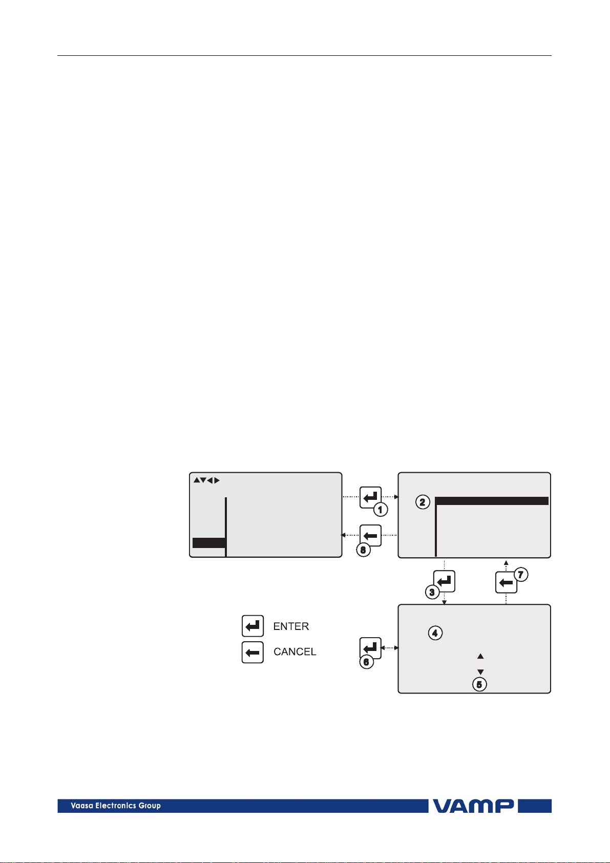
2.2.1. Navigating in menus
All the menu functions are based on the main menu/submenu
structure:
1. Use the arrow keys UP and DOWN to move up and down in
the main menu.
2. To move to a submenu, repeatedly push the RIGHT key
until the required submenu is shown. Correspondingly,
push the LEFT key to return to the main menu.
3. Push the ENTER key to confirm the selected submenu. If
there are more than six items in the selected submenu, a
black line appears to the right side of the display (Figure
2.2.1-1). It is then possible to scroll down in the submenu.
scroll
ENABLED STAGES 3
Evnt
DR
DI
DO
Prot
I>
Figure 2.2.1-1 Example of scroll indication
I>
I>>
I>>>
I2>
Io>
Io>>
On
On
On
Off
Off
Off
4. Push the CANCEL key to cancel a selection.
5. Hold the CANCEL key pushed for appr. 4 sec. to display the
title screen.
6. Pushing the UP or DOWN key in any position of a
submenu, when it is not selected, brings you directly one
step up or down in the main menu.
The active main menu selection is indicated with black
background color. The possible navigating directions in the
menu are shown in the upper-left corner by means of black
triangular symbols.
10
VAMP 24h support phone +358 (0)20 753 3264 VM50.EN004
Operation and configuration 2 Local panel user interface 2.2 Local panel operations
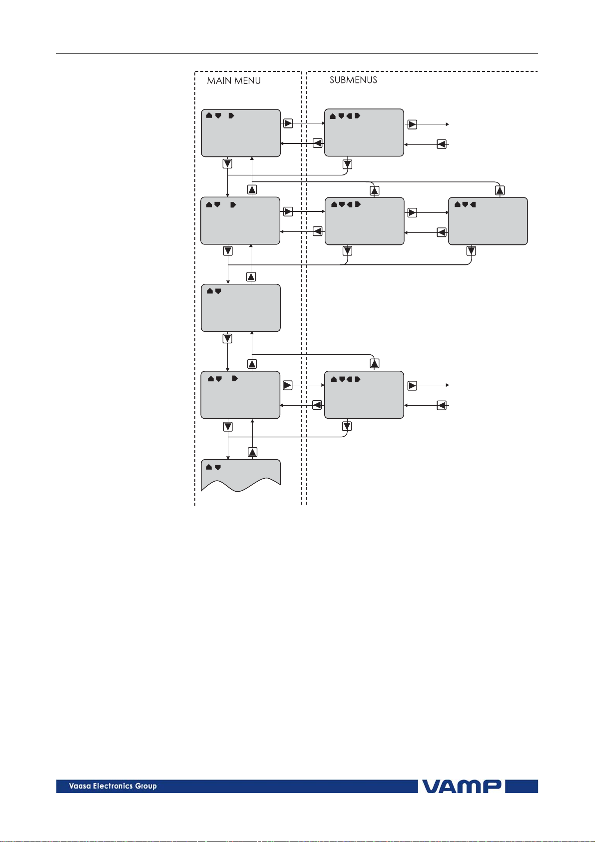
Figure 2.2.1-2 Principles of the menu structure and navigation in the menus
7. Push the INFO key and then the ENTER key to give the
password.
8. Push the INFO key to obtain additional information about
any menu item.
9. Push the CANCEL key to revert to the normal display.
Main menu
The general menu structure is shown in Figure 2.2.1-2. The
menu is dependent on the user’s configuration and the options
according the order code. For example only the enabled
protection stages will appear in the menu.
VM50.EN004 VAMP 24h support phone +358 (0)20 753 3264
11

2.2 Local panel operations 2 Local panel user interface Operation and configuration
A list of the local main menu
Main
menu
Number
of
Description
ANSI
code
menus
1 Interactive mimic display 1
5
Double size measurements
1
defined by the user
1
Title screen with device name,
time and firmware version.
Meas 7 Measurements
Imax 8
Time stamped min & max of
currents
Mont 17
Maximum values of the last 31
days and the last twelve
months
Evnt 2 Events
DR 3 Disturbance recorder 2
Runh 1
Running hour counter. Active
time of a selected digital input
and time stamps of the latest
start and stop.
TIMR 6 Day and week timers
DI 4
Digital inputs including virtual
inputs
DO 3
Digital outputs (relays) and
output matrix
ExtAI External analogue inputs 3
ExDI External digital inputs 3
ExDO External digital outputs 3
Prot 18
Protection counters, combined
overcurrent status, protection
status, protection enabling, cold
load and inrush detectionIf2>
and block matrix
I> 12 1st overcurrent stage 50/51 4
I>> 11 2nd overcurrent stage 50/51 4
I>>> 11 3rd overcurrent stage 50/51 4
I< 11 Undercurrent stage 37 4
I2/I1> 11 Broken conductor prot. Stage 46R 4
I2> 10 Unbalance stage 46 4
I2>> 10
Phase reversal / incorrect phase
47 4
sequence stage
Ist> 10 Stall protection stage 48 4
N> 11 Frequent start 66 4
T> 3 Thermal overload stage 49 4
Io> 12 1st earth fault stage 50N/51N 4
Io>> 11 2nd earth fault stage 50N/51N 4
Io>>> 11 3rd earth fault stage 50N/51N 4
Io>>>> 11 4th earth fault stage 50N/51N 4
Prg1 11 1st programmable stage 4
Note
12
VAMP 24h support phone +358 (0)20 753 3264 VM50.EN004

Operation and configuration 2 Local panel user interface 2.2 Local panel operations
Main
menu
Prg2 11 2nd programmable stage 4
Prg3 11 3rd programmable stage 4
Prg4 11 4th programmable stage 4
Prg5 11 5th programmable stage 4
Prg6 11 6th programmable stage 4
Prg7 11 7th programmable stage 4
Prg8 11 8th programmable stage 4
If2> 3 Second harmonic O/C stage 51F2 4
CBFP 10
CBWE 5
CTSV 1 CT supervisor 4
ArcI> 11
ArcIo> 10
ArcIo2> 10
AR 4 Auto-reclose 79 8
OBJ 10 Object definitions 5
Lgic 2
CONF 9 Device setup, scaling etc. 6
Bus 11
Diag 9 Device selfdiagnosis
Notes
1 Configuration is done with VAMPSET
2 Recording files are read with VAMPSET
3
The menu is visible only if protocol "ExternalIO" is selected for one of
the serial ports. Serial ports are configured in menu "Bus".
4 The menu is visible only if the stage is enabled.
5 Objects are circuit breakers, disconnectors etc.
6
There are two extra menus, which are visible only if the access level
"operator" or "configurator" has been opened with the corresponding
password.
7 Detailed protocol configuration is done with VAMPSET.
8 VAMP51 and VAMP52
Number
of
menus
Circuit breaker failure
protection
Circuit breaker wearing
supervision
Optional arc protection stage
for phase-to-phase faults and
delayed light signal.
Optional arc protection stage
for earth faults. Current input
= I01
Optional arc protection stage
for earth faults. Current input
= I02
Status and counters of user's
logic
Serial port and protocol
configuration
Description
ANSI
code
50BF 4
4
50ARC 4
50NARC 4
50NARC 4
1
7
Note
2.2.2. Menu structure of protection functions
The general structure of all protection function menus is
similar although the details do differ from stage to stage. As an
VM50.EN004 VAMP 24h support phone +358 (0)20 753 3264
13

2.2 Local panel operations 2 Local panel user interface Operatio n and configuration
example the details of the second overcurrent stage I>> menus
are shown below.
First menu of I>> 50/51 stage
first menu
I>> STATUS 50 / 51
ExDO
Prot
I>
I>>
Iv>
I>
Figure 2.2.2-1 First menu of I>> 50/51 stage
Status
SCntr
TCntr
SetGrp
SGrpDI
Force
OFF
5
2
1
-
This is the status, start and trip counter and setting group
menu. The content is:
Status –
The stage is not detecting any fault at the moment. The
stage can also be forced to pick-up or trip is the operating
level is “Configurator” and the force flag below is on.
Operating levels are explained in chapter 2.2.5
SCntr 5
The stage has picked-up a fault five times since the last
reset or restart. This value can be cleared if the operating
level is at least “Operator”.
TCntr 2
The stage has tripped two times since the last reset or
restart. This value can be cleared if the operating level is at
least “Operator”.
SetGrp 1
The active setting group is one. This value can be edited if
the operating level is at least “Operator”. Setting groups are
explained in chapter 2.2.3.
SGrpDI –
The setting group is not controlled by any digital input. This
value can be edited if the operating level is at least
“Configurator”.
Force Off
The status forcing and output relay forcing is disabled. This
force flag status can be set to “On” or back to “Off” if the
operating level is at least “Configurator”. If no front panel
button is pressed within five minutes and there is no
VAMPSET communication, the force flag will be set to “Off”
position. The forcing is explained in Chapter 2.3.4.
14
VAMP 24h support phone +358 (0)20 753 3264 VM50.EN004

Operation and configuration 2 Local panel user interface 2.2 Local panel operations
Second menu of I>> 50/51 stage
second menu
I>> SET 50 / 51
Stage setting group 1
ExDI
ExDO
Prot
I>>
CBWE
OBJ
Figure 2.2.2-2 Second menu(next on the right) of I>> 50/51 stage
ILmax
Status
I>>
I>>
t>>
403A
-
1013A
2.50xIn
0.60s
This is the main setting menu. The content is:
Stage setting group 1
These are the group 1 setting values. The other setting
group can be seen by pressing push buttons ENTER and
then RIGHT or LEFT. Setting groups are explained in
chapter 2.2.3.
ILmax 403A
The maximum of three measured phase currents is at the
moment 403 A. This is the value the stage is supervising.
Status –
Status of the stage. This is just a copy of the status value in
the first menu.
I>> 1013 A
The pick-up limit is 1013 A in primary value.
I>> 2.50xIn
The pick-up limit is 2.50 times the rated current of the
generator. This value can be edited if the operating level is
at least “Operator”. Operating levels are explained in
chapter 2.2.5.
t>> 0.60s
The total operation delay is set to 600 ms. This value can be
edited if the operating level is at least “Operator”.
VM50.EN004 VAMP 24h support phone +358 (0)20 753 3264
15

2.2 Local panel operations 2 Local panel user interface Operatio n and configuration
Third menu of I>> 50/51 stage
third menu
I>> LOG 50/51
FAULT LOG 1
ExDI
ExDO
Prot
I>>
CBWE
OBJ
2006-09-14
12:25:10.288
Type
Flt
Load
EDly
1-2
2.86xIn
0.99xIn
81%
SetGrp 1
Figure 2.2.2-3 Third and last menu (next on the right) of I>> 50/51 stage
This is the menu for registered values by the I>> stage. Fault
logs are explained in chapter 2.2.4.
FAULT LOG 1
This is the latest of the eight available logs. You may move
between the logs by pressing push buttons ENTER and then
RIGHT or LEFT.
2006-09-14
Date of the log.
12:25:10.288
Time of the log.
Type 1-2
The overcurrent fault has been detected in phases L1 and
L2 (A & B, red & yellow, R/S, u&v).
Flt 2.86xIn
The fault current has been 2.86 per unit.
Load 0.99xIn
The average load current before the fault has been 0.99 pu.
EDly 81%
The elapsed operation delay has been 81% of the setting
0.60 s = 0.49 s. Any registered elapsed delay less than 100 %
means that the stage has not tripped, because the fault
duration has been shorter that the delay setting.
SetGrp 1
The setting group has been 1. This line can be reached by
pressing ENTER and several times the DOWN button.
16
VAMP 24h support phone +358 (0)20 753 3264 VM50.EN004
Operation and configuration 2 Local panel user interface 2.2 Local panel operations
2.2.3. Setting groups
Most of the protection functions of the relay have two setting
groups. These groups are useful for example when the network
topology is changed frequently. The active group can be
changed by a digital input, through remote communication or
locally by using the local panel.
The active setting group of each protection function can be
selected separately. Figure 2.2.3-1 shows an example where the
changing of the I> setting group is handled with digital input
one (SGrpDI). If the digital input is TRUE, the active setting
group is group two and correspondingly, the active group is
group one, if the digital input is FALSE. If no digital input is
selected (SGrpDI = -), the active group can be selected by
changing the value of the parameter SetGrp.
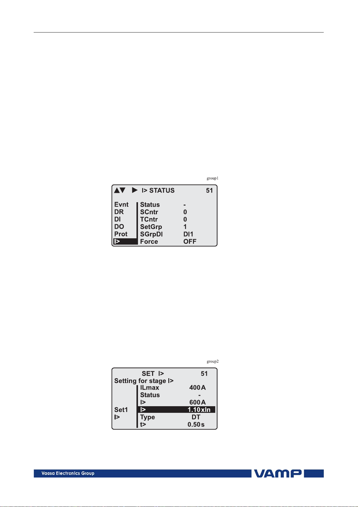
Figure 2.2.3-1 Example of protection submenu with setting group
parameters
The changing of the setting parameters can be done easily.
When the desired submenu has been found (with the arrow
keys), press the ENTER key to select the submenu. Now the
selected setting group is indicated in the down-left corner of the
display (See Figure 2.2.3.-2). Set1 is setting group one and Set2
is setting group two. When the needed changes, to the selected
setting group, have been done, press the LEFT or the RIGHT
key to select another group (the LEFT key is used when the
active setting group is 2 and the RIGHT key is used when the
active setting group is 1).
Figure 2.2.3-2 Example of I> setting submenu
VM50.EN004 VAMP 24h support phone +358 (0)20 753 3264
17
2.2 Local panel operations 2 Local panel user interface Operatio n and configuration
2.2.4. Fault logs
All the protection functions include fault logs. The fault log of a
function can register up to eight different faults with time
stamp information, fault values etc. The fault logs are stored in
non-volatile memory. Each function has its own logs. The fault
logs are not cleared when power is switched off. The user is
able to clear all logs using VAMPSET. Each function has its
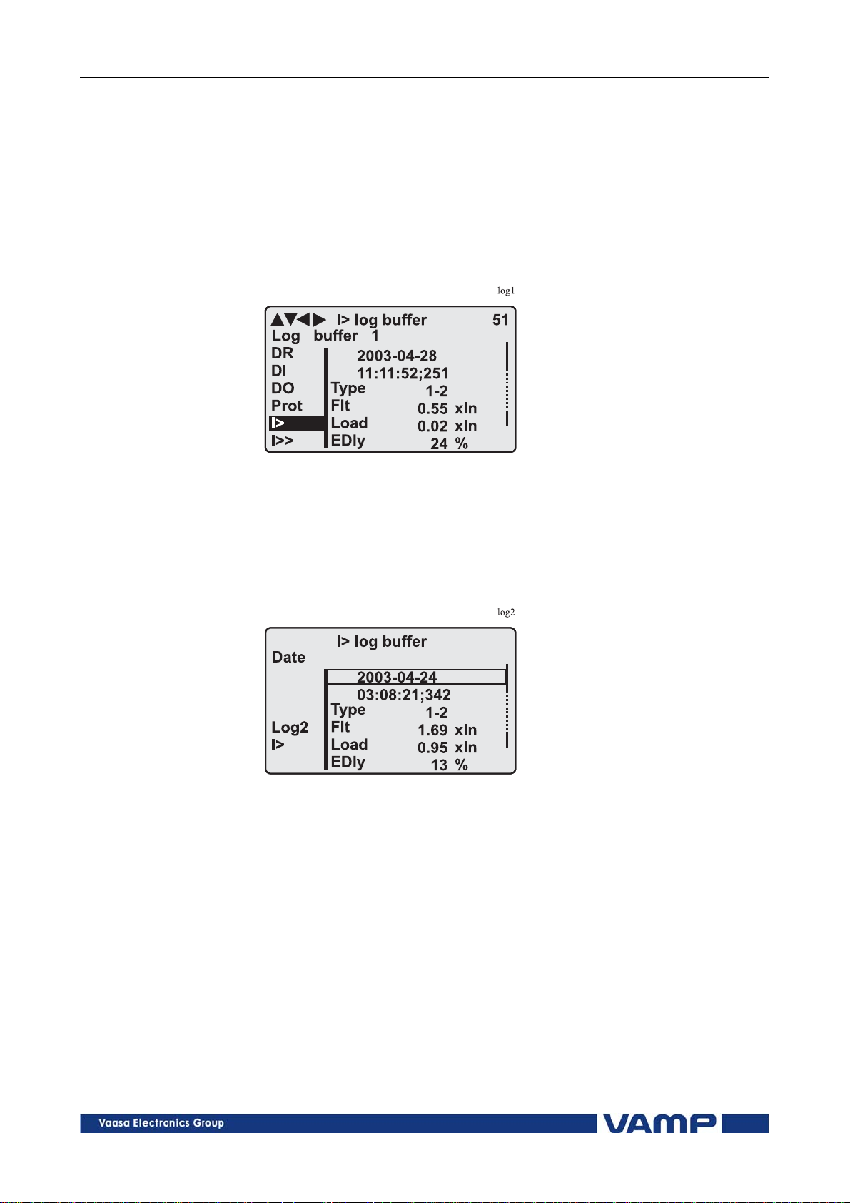
own logs (See Figure 2.2.4-1).
Figure 2.2.4-1 Example of fault log
To see the values of, for example, log two, press then ENTER
key to select the current log (log one). The current log number
is then indicated in the down-left corner of the display (See
Figure 2.2.4-2, Log2 = log two). The log two is selected by
pressing the RIGHT key once.
Figure 2.2.4-2 Example of selected fault log
18
VAMP 24h support phone +358 (0)20 753 3264 VM50.EN004

Operation and configuration 2 Local panel user interface 2.2 Local panel operations
2.2.5. Operating levels
The relay has three operating levels: User level, Operator level
and Configurator level. The purpose of the access levels is to
prevent accidental change of relay configurations, parameters
or settings.
USER level
Use: Possible to read e.g. parameter values,
measurements and events
Opening: Level permanently open
Closing: Closing not possible
OPERATOR level
Use: Possible to control objects and to change e.g.
the settings of the protection stages
Opening: Default password is 1
Setting state: Push ENTER
Closing: The level is automatically closed after 10
minutes idle time. Giving the password 9999
can also close the level.
CONFIGURATOR level
Use: The configurator level is needed during the
commissioning of the relay. E.g. the scaling of
the voltage and current transformers can be
set.
Opening: Default password is 2
Setting state: Push ENTER
Closing: The level is automatically closed after 10
minutes idle time. Giving the password 9999
can also close the level.
VM50.EN004 VAMP 24h support phone +358 (0)20 753 3264
19

2.2 Local panel operations 2 Local panel user interface Operatio n and configuration
Opening access
1. Push the INFO key and the ENTER key on the front panel
ENTER PASSWORD
0
***
Figure 2.2.5-1 Opening the access level
2. Enter the password needed for the desired level: the
password can contain four digits. The digits are supplied
one by one by first moving to the position of the digit using
the RIGHT key and then setting the desired digit value
using the UP key.
3. Push the ENTER key.
Password handling
The passwords can only be changed using VAMPSET software
connected to the USB -port in front of the relay.
It is possible to restore the password(s) in case the password is
lost or forgotten. In order to restore the password(s), a relay
program is needed. The virtual serial port settings are 38400
bps, 8 data bits, no parity and one stop bit. The bit rate is
configurable via the front panel.
Command Description
get pwd_break
get serno
Send both the numbers to vampsupport@vamp.fi and ask for a
password break. A device specific break code is sent back to
you. That code will be valid for the next two weeks.
Command Description
set pwd_break=4435876
Now the passwords are restored to the default values (See
chapter 2.2.5).
Get the break code (Example:
6569403)
Get the serial number of the relay
(Example: 12345)
Restore the factory default
passwords (“4435876” is just an
example. The actual code should be
asked from VAMP Ltd.)
20
VAMP 24h support phone +358 (0)20 753 3264 VM50.EN004

Operation and configuration 2 Local panel user interface 2.3 Operating measures
2.3. Operating measures
2.3.1. Control functions
The default display of the local panel is a single-line diagram
including relay identification, Local/Remote indication, Autoreclose on/off selection and selected analogue measurement
values.
Please note that the operator password must be active in order
to be able to control the objects. Please refer to page 20 opening
access.
Toggling Local/Remote control
1. Push the ENTER key. The previously activated object
starts to blink.
2. Select the Local/Remote object (“L” or “R” squared) by
using the arrow keys.
3. Push the ENTER key. The L/R dialog opens. Select
“REMOTE” to enable remote control and disable local
control. Select “LOCAL” to enable local control and
disable remote control.
4. Confirm the setting by pushing the ENTER key. The
Local/Remote state will change.
Object control
1. Push the ENTER key. The previously activated object
starts to blink.
2. Select the object to control by using the arrow keys.
Please note that only controllable objects can be selected.
3. Push the ENTER key. A control dialog opens.
4. Select the “Open” or “Close” command by using the UP
and DOWN arrow keys.
5. Confirm the operation by pushing the ENTER key. The
state of the object changes.
Toggling virtual inputs
1. Push the ENTER key. The previously activated object
starts to blink.
2. Select the virtual input object (empty or black square)
3. The dialog opens
4. Select “VIon” to activate the virtual input or select
“VIoff” to deactivate the virtual input
VM50.EN004 VAMP 24h support phone +358 (0)20 753 3264
21

2.3 Operating measures 2 Local panel user interface Operation and configuration
2.3.2. Measured data
The measured values can be read from the Meas menu and its
submenus. Furthermore, any measurement value in the
following table can be displayed on the main view next to the
single line diagram. Up to six measurements can be shown.
Value Menu/Submenu Description
IL1 MEAS/PHASE CURRENTS Phase current IL1 [A]
IL2 MEAS/PHASE CURRENTS Phase current IL2 [A]
IL3 MEAS/PHASE CURRENTS Phase current IL3 [A]
IL1da
IL2da
IL3da
Io
IoC
I1
I2
I2/I1
Uo MEAS/MISCELLANEOUS
f MEAS/MISCELLANEOUS Frequency [Hz]
THDIL
THDIL1
THDIL2
THDIL3
IL1har HARMONICS of IL1 Harmonics of phase current IL1 [%]
IL2har HARMONICS of IL2 Harmonics of phase current IL2 [%]
IL3har HARMONICS of IL3 Harmonics of phase current IL3 [%]
MEAS /PHASE
CURRENTS
MEAS /PHASE
CURRENTS
MEAS /PHASE
CURRENTS
MEAS /SYMMETRIC
CURRENTS
MEAS /SYMMETRIC
CURRENTS
MEAS /SYMMETRIC
CURRENTS
MEAS /SYMMETRIC
CURRENTS
MEAS /SYMMETRIC
CURRENTS
MEAS /HARM.
DISTORTION
MEAS /HARM.
DISTORTION
MEAS /HARM.
DISTORTION
MEAS /HARM.
DISTORTION
15 min average for IL1 [A]
15 min average for IL2 [A]
15 min average for IL3 [A]
Primary value of zerosequence/
residual current Io [A]
Calculated Io [A]
Positive sequence current [A]
Negative sequence current [A]
Negative sequence current related
to positive sequence current (for
unbalance protection) [%]
Residual voltage Uo [%] (Only in
VAMP52)
Total harmonic distortion of the
mean value of phase currents [%]
Total harmonic distortion of phase
current IL1 [%]
Total harmonic distortion of phase
current IL2 [%]
Total harmonic distortion of phase
current IL3 [%]
22
VAMP 24h support phone +358 (0)20 753 3264 VM50.EN004

Operation and configuration 2 Local panel user interface 2.3 Operating measures
Figure 2.3.2-1. Example of harmonics bar display
2.3.3. Reading event register
The event register can be read from the Evnt submenu:
1. Push the RIGHT key once.
2. The EVENT LIST appears. The display contains a list of all
the events that have been configured to be included in the
event register.
Figure 2.3.3-1. Example of an event register
3. Scroll through the event list with the UP and DOWN keys.
4. Exit the event list by pushing the LEFT key.
It is possible to set the order in which the events are sorted. If
the “Order” -parameter is set to “New-Old”, then the first event
in the EVENT LIST is the most recent event.
VM50.EN004 VAMP 24h support phone +358 (0)20 753 3264
23
2.3 Operating measures 2 Local panel user interface Operation and configuration
2.3.4. Forced control (Force)
In some menus it is possible to switch a function on and off by
using a force function. This feature can be used, for instance,
for testing a certain function. The force function can be
activated as follows:
1. Move to the setting state of the desired function, for
example DO (see chapter 2.4, on page 25).
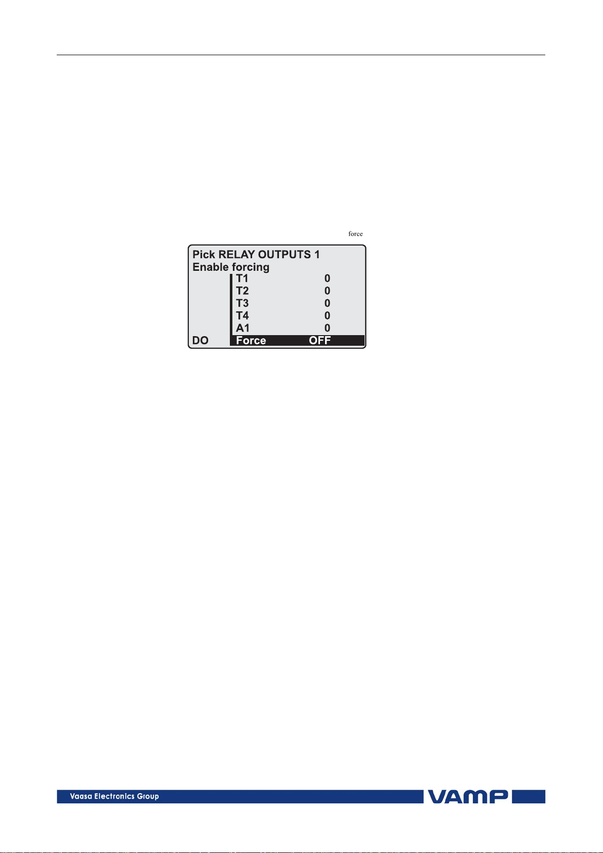
2. Select the Force function (the background color of the force
text is black).
Figure 2.3.4-1 Selecting Force function
3. Push the ENTER key.
4. Push the UP or DOWN key to change the "OFF" text to
"ON", that is, to activate the Force function.
5. Push the ENTER key to return to the selection list. Choose
the signal to be controlled by force with the UP and DOWN
keys, for instance the T1 signal.
6. Push the ENTER key to confirm the selection. Signal T1
can now be controlled by force.
7. Push the UP or DOWN key to change the selection from "0"
(not alert) to "1" (alert) or vice versa.
8. Push the ENTER key to execute the forced control operation
of the selected function, e.g., making the output relay of T1
to pick up.
9. Repeat the steps 7 and 8 to alternate between the on and off
state of the function.
10. Repeat the steps 1...4 to exit the Force function.
11. Push the CANCEL key to return to the main menu.
24
NOTE! All the interlockings and blockings are bypassed when the force control
is used.
VAMP 24h support phone +358 (0)20 753 3264 VM50.EN004

Operation and configuration 2 Local panel user interface 2.4 Configuration and paramete
r
setting
2.4. Configuration and parameter setting
The minimum procedure to configure a relay is
1. Open the access level "Configurator". The default password
for configurator access level is 2.
2. Set the rated values in menu [CONF] including at least
current transformers, voltage transformers and generator
ratings. Also the date and time settings are in this same
main menu.
3. Enable the needed protection functions and disable the rest
of the protection functions in main menu [Prot].
4. Set the setting parameter of the enable protection stages
according the application.
5. Connect the output relays to the start and trip signals of the
enabled protection stages using the output matrix. This can
be done in main menu [DO], although the VAMPSET
program is recommended for output matrix editing.
6. Configure the needed digital inputs in main menu [DI].
7. Configure blocking and interlockings for protection stages
using the block matrix. This can be done in main menu
[Prot], although VAMPSET is recommended for block
matrix editing.
Some of the parameters can only be changed via the USB-port
using the VAMPSET software. Such parameters, (for example
passwords, blockings and mimic configuration) are normally set
only during commissioning.
Some of the parameters require the restarting of the relay. This
restarting is done automatically when necessary. If a
parameter change requires restarting, the display will show as
Figure 2.4-1.
Figure 2.4-1 Example of auto-reset display
Press CANCEL to return to the setting view. If a parameter
must be changed, press the ENTER key again. The parameter
can now be set. When the parameter change is confirmed with
the ENTER key, a [RESTART]- text appears to the top-right
corner of the display. This means that auto-resetting is
VM50.EN004 VAMP 24h support phone +358 (0)20 753 3264
25
2.4 Configuration and parameter
setting
2 Local panel user interface Operation and configuration
pending. If no key is pressed, the auto-reset will be executed
within few seconds.
2.4.1. Parameter setting
1. Move to the setting state of the desired menu (for example
CONF/CURRENT SCALING) by pushing the ENTER key.
The Pick text appears in the upper-left part of the display.
2. Enter the password associated with the configuration level
by pushing the INFO key and then using the arrow keys
and the ENTER key (default value is 0002). For more
information about the access levels, please refer to Chapter
2.2.5.
3. Scroll through the parameters using the UP and DOWN
keys. A parameter can be set if the background color of the
line is black. If the parameter cannot be set the parameter
is framed.
4. Select the desired parameter (for example Inom) with the
ENTER key.
5. Use the UP and DOWN keys to change a parameter value.
If the value contains more than one digit, use the LEFT and
RIGHT keys to shift from digit to digit, and the UP and
DOWN keys to change the digits.
6. Push the ENTER key to accept a new value. If you want to
leave the parameter value unchanged, exit the edit state by
pushing the CANCEL key.
paramm
CURRENT SCALING
I>
Io>
Io>
>
CBFP
CONF
Inom
Isec
Ionom
Iosec
Ioinp
200A
5A
100A
1.0A
1.0A
Figure 2.4.1-1.Changing parameters
PICK CURRENT SCALING
CT primary
CONF
Edit VALUE CHANGE
CT primary
Inom
Isec
Ionom
Iosec
Ioinp
200
200A
5A
100A
1.0A
1.0A
26
VAMP 24h support phone +358 (0)20 753 3264 VM50.EN004
Operation and configuration 2 Local panel user interface 2.4 Configuration and parameter
setting
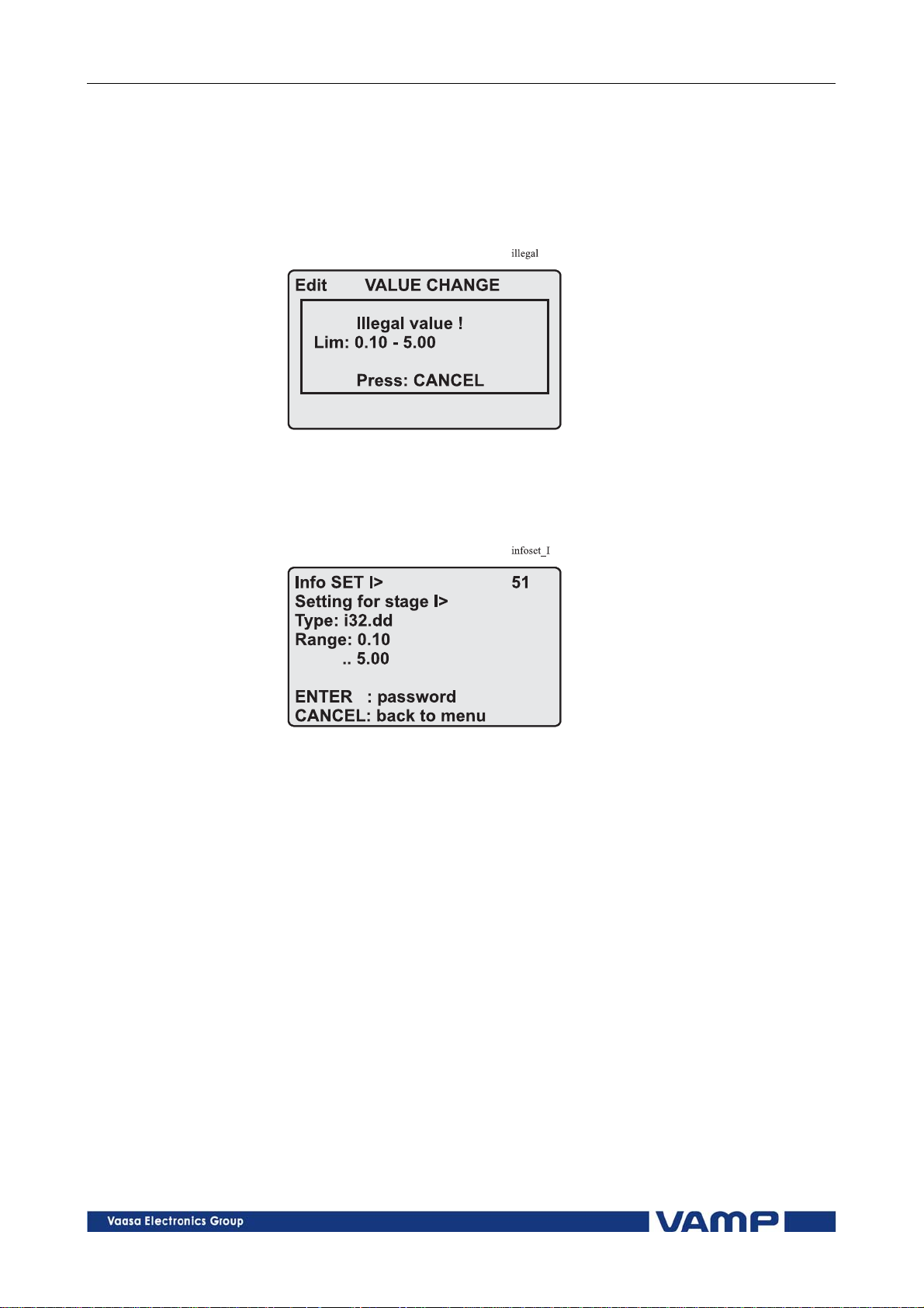
2.4.2. Setting range limits
If the given parameter setting values are out-of-range values, a
fault message will be shown when the setting is confirmed with
the ENTER key. Adjust the setting to be within the allowed
range.
Figure 2.4.2-1 Example of a fault message
The allowed setting range is shown in the display in the setting
mode. To view the range, push the INFO key. Push the
CANCEL key to return to the setting mode.
Figure 2.4.2-2 Allowed setting ranges show in the display
2.4.3. Disturbance recorder menu DR
Via the submenus of the disturbance recorder menu the
following functions and features can be read and set:
DISTURBANCE RECORDER
Recording mode (Mo
Sample rate (SR)
Recording time (Time)
Pre trig time (PreTrig)
Manual trigger (ManTrig)
Count of ready records (ReadyRec)
REC. CHANNELS
Add a link to the recorder (AddCh)
Clear all links (ClrCh)
de)
VM50.EN004 VAMP 24h support phone +358 (0)20 753 3264
27

2.4 Configuration and parameter
setting
2 Local panel user interface Operation and configuration
Available links:
DO, DI
IL
I2/In, I2/I1, I2, I1, IoCalc
f
Io
IL3, IL2, IL1
THDIL1, THDIL2, THDIL3
IL1RMS, IL2RMS, IL3RMS
ILmin
ILmax
T
Uo, U12 or UL1 depending on the voltage measurement
mode. (VAMP 52 only)
2.4.4. Configuring digital inputs DI
The following functions can be read and set via the submenus
of the digital inputs menu:
The status of digital inputs (DIGITAL INPUTS 1,2)
Operation counters (DI COUNTERS)
Operation delay (DELAYs for DigIn)
The polarity of the input signal (INPUT POLARITY). Either
normally open (NO) or normally closed (NC) circuit.
Event enabling EVENT MASK1
2.4.5. Configuring digital outputs DO
The following functions can be read and set via the submenus
of the digital outputs menu:
The status of the output relays (RELAY OUTPUTS1 and 2)
The forcing of the output relays (RELAY OUTPUTS1 and 2)
(only if Force = ON):
o Forced control (0 or 1) of the Trip relays
o Forced control (0 or 1) of the Alarm relays
o Forced control (0 or 1) of the IF relay
The configuration of the output signals to the output relays.
The configuration of the operation indicators (LED) Alarm
and Trip and application specific alarm leds A, B, C, D, E, F,
G and H (that is, the output relay matrix).
NOTE! The amount of Trip and Alarm relays depends on the relay type and
optional hardware.
28
VAMP 24h support phone +358 (0)20 753 3264 VM50.EN004

Operation and configuration 2 Local panel user interface 2.4 Configuration and parameter
setting
2.4.6. Configuring analogue outputs AO (Option)
Via the submenus of the analogue output menu the following
functions can be read and set:
ANALOG OUTPUT
Value of AO1 (AO1)
Forced control of analogue output (Force)
ANALOG OUTPUT
Value linked to the analogue output (Lnk1)
(See list available links)
Scaled minimum of linked value (Min)
Scaled maximum of linked value (Max)
Scaled minimum of analogue output (AOmin)
Scaled maximum of analogue output (AOmax)
Value of analogue output (AO1)
Available links:
IL1, IL2, IL2
F
IL
Io, IoCalc
U12
UL1
2.4.7. Protection menu Prot
The following functions can be read and set via the submenus
of the Prot menu:
Reset all the counters (PROTECTION SET/ClAll)
Read the status of all the protection functions (PROTECT
STATUS 1-x)
Enable and disable protection functions (ENABLED
STAGES 1-x)
Define the interlockings using block matrix (only with
VAMPSET).
Each stage of the protection functions can be disabled or
enabled individually in the Prot menu. When a stage is
enabled, it will be in operation immediately without a need to
reset the relay.
The relay includes several protection functions. However, the
processor capacity limits the number of protection functions
that can be active at the same time.
VM50.EN004 VAMP 24h support phone +358 (0)20 753 3264
29

2.4 Configuration and parameter
setting
2 Local panel user interface Operation and configuration
2.4.8. Configuration menu CONF
The following functions and features can be read and set via
the submenus of the configuration menu:
DEVICE SETUP
Bit rate for the command line interface in communication
ports and the USB-port in the front panel. The front panel
is always using this setting. If SPABUS is selected for the
rear panel port, the bit rate is according SPABUS settings.
Access level [Acc]
LANGUAGE
List of available languages in the relay
CURRENT SCALING
Rated phase CT primary current (Inom)
Rated phase CT secondary current (Isec)
Rated input of the relay [Iinput]is 5 A
Rated value of I
Rated value of I
Rated I
input of the relay [Ioinp] is 5 A / 1 A or 1 A / 0.2 A.
01
This is specified in the order code of the device.
The rated input values are usually equal to the rated secondary
value of the CT.
CT primary current (Ionom)
01
CT secondary current (Iosec)
01
The rated CT secondary may be greater than the rated input
but the continuous current must be less than four times the
rated input. In compensated, high impedance earthed and
isolated networks using cable transformer to measure residual
current I0, it is quite usual to use a relay with 1 A or 0.2 A
input although the CT is 5 A or 1A. This increases the
measurement accuracy.
The rated CT secondary may also be less than the rated input
but the measurement accuracy near zero current will decrease.
MOTOR SETTING
Rated current of the motor (Imot).
VOLTAGE SCALING (only VAMP52)
Rated Uo VT secondary voltage (Uosec)
Voltage measuring mode (Umode)
DEVICE INFO
Relay type
(Type VAMP 5X)
Serial number (SerN)
Software version (PrgVer)
Bootcode version (BootVer)
30
VAMP 24h support phone +358 (0)20 753 3264 VM50.EN004
 Loading...