


INSTRUCTIONS MANUAL
AIRBRUSH MANUAL EXTERNAL MIX EQUIPMENT
1
CONTENTS
WELCOME . . . . . . . 2
STATEMENT OF COMPLIANCE . . . . . 3
WARRANTY . . . . . . . 4
1. EQUIPMENT DESCRIPTION . . . . . 5
2. TRANSPORT, HANDLING AND STORAGE . . . 9
3. OPERATION . . . . . . . 9
3.1. Safety rules . . . . . . 9
3.2. Starting-up the equipment. . . . . 10
3.3. Calibration . . . . . . 12
4. MAINTENANCE AND CLEANING . . . . 15
5. SAFETY RULES . . . . . . 16
6. DISASSEMBLY CONDITIONS . . . . . 16
MANUAL EXTERNAL MIX SET-UP CHART . . . 17
VISCOSITY EVOLUTION IN ACCORDANCE
WITH SOLVENT-BASED PAINTS TERMPERATURE . . 20
APPLICATION GUN EXPLODED . . . . . 21
MAINTENANCE OPERATIONS . . . . . 25

INSTRUCTIONS MANUAL
AIRBRUSH MANUAL EXTERNAL MIX EQUIPMENT
2
Dear costumer:
Our work at VALVER AIR SPEED involves manufacturing different painting equipment and
application systems for users and companies consuming varnishes and paints.
Specifically, the AIRBRUSH MANUAL EXTERNAL MIX EQUIPMENT guarantees absolute
compliance with product manufacturers’ instructions. It also guarantees a correct, uniform mix.
The mixture is prepared outside the equipment - no internal process – offering advantages in
cleaning and time, product and diluent savings. It is only used the solvent required to dilute the
mixture to be applied. The mixtures are accurate and the mixing ratio control is carried out by hand.
We offer automatic modules for mixture calibration depending upon the mixture percentages and the
nature of each product. If you are interested, do not hesitate to contact us.
The system and the TRIMIX® external mix heads have been developed by VALVER AIR
SPEED S.L. after a long term of investigation, development and tests carried out by our design and
R+D team. We have improved the existing heads in the market obtaining the catalyst or component B
mixture and integration together with the resin or component A. Thanks to a careful and studied
design with compressed air sprayer at both ends of the principal product´s output we have achieved a
perfect spray area for the colour application free from any imperfection.
The external mix has been tested with numerous products obtaining a perfect application
and full compliance with the characteristics of the product as indicated by the manufacturer. Due to
lack of knowledge concerning the whole range of two-component-chemicals available in the market,
unfortunately we cannot ensure all possible applications. Before purchasing external mix equipment
from VALVER AIR SPEED S.L. we recommend to carry out the necessary product tests prior to
production.
VALVER AIR SPEED thanks you for your trust in having chosen one of our products and
would like to inform you that if any problem should arise or simply a need for enquiries or
personalised advice, you should please get in touch with our company’s official technical and
maintenance service, as stated below:
TECHNICALSERVICE/ MAINTENANCE
VALVER AIR SPEED, S.L.
Pol. Industrial La Pascualeta
Camino viejo de Picasent s/n
46200 PAIPORTA (VALENCIA) SPAIN
Tel. 96 397 58 16 / Fax. 96 397 58 15

INSTRUCTIONS MANUAL
AIRBRUSH MANUAL EXTERNAL MIX EQUIPMENT
3
STATEMENT OF COMPLIANCE
Mr. Ricardo Verdú, as Manager of the company VALVER AIR SPEED, S.L. manufacturer of the
equipment for paint application, whose registered office is at Polígono Industrial La Pascualeta, Cno.
Viejo de Picasent, s/n 46200 PAIPORTA (VALENCIA) Spain. Declares at his own sole responsability that
the machine:
MAKE: VALVER
DESCRIPTION: AIRBRUSH MANUAL EXTERNAL MIX EQUIPMENT
MODEL: SERIAL Nº:
DATE OF MANUFACTURE:
As described in the enclosed documents, complies with the essential requisites of the following
Community Directives:
x
2006/42/CE Machinery Safety Directive.
That all the aspects covered in the following harmonised standards were taken into account in
its the design and manufacture:
x
UNE-EN ISO 12100:2012. Safety of machinery. General principles for design. Risk assessment and
risk reduction.
x
UNE-EN ISO 4414:2011. Pneumodrives. General rules and safety requirements for systems and their
components.
x
UNE-EN 626-1:1995+A1:2008. Safety of machinery. Reduction of risks to health from hazardous
substances emitted by machinery.
x
UNE-EN 12621:2006+A1:2010. Machinery for the supply and circulation of coating materials under
pressure. Safety requirements.
x
UNE-EN 12162:2001+A1:2009. Pumps for liquids. Safety requirements. Hydrostatic Test Procedure.
x
UNE-EN 809:1999+A1:2010. Pumps and pump units for liquids group. Common safety
requirements.
That has been constituted the corresponding technical process of construction; and in order
that it consists to the opportune effects it issues the present statement of compliance.
In Valencia,
VALVER AIR SPEED, S.L.
Fdo. Ricardo Verdú

INSTRUCTIONS MANUAL
AIRBRUSH MANUAL EXTERNAL MIX EQUIPMENT
4
NAME: _________________________________________________________________________________________
COMPANY NAME: ____________________________________________________________________________
ADDRESS: _________________________________________________________________________________
MODEL OF MACHINE: _______________________________________________________________________
SERIAL NO.: ______________________________________________________________________________
DATE: _________________________________________________________________________________
STAMP AND SIGNATURE:
___ ___ ___ ___ ___ ___ ___ ___ ___ ___ ___ ___ ___ ___ ___ ___ ___ ___ ___ ___ ___ ___ ___ ___ ___
Description: AIRBRUSH MANUAL EXTERNAL MIX EQUIPMENT
Model:
Serial nº:
All equipment has 2 years warranty from the date of the invoice: The warranty covers the replacement
or repair of the machine’s components and Valver Air Speed S.L.’s acknowledgement that they are faulty due to
manufacturing errors, in addition to the labour involved in the replacement and/or repair of parts. Service during
the warranty will only be valid if it is carried out by Valver Air Speed S.L. in its own workshops.
The materials will be sent with the postage paid and once the machinery has been repaired it will be
returned to the client, who must pay for the postage. The warranty does not include our engineers working in the
place where the machine is installed or the dismantling of the machinery. If it is absolutely necessary to send
Valver Air Speed S.L. staff out, it will always be done at their own discretion and an invoice will be issued for the
job plus the travelling expenses.
This warranty will only be valid if it is signed, stamped and dated by Valver Air Speed S.L. and it must
also be accompanied by the receipt of purchase for the machine under warranty.
The warranty does not include:
-Compensation for either direct or indirect damage caused by our machines to objects or people. Likewise, it
does not include repairs carried out by the client or by third parties.
-Breakdowns caused by inappropriate use or assembly.
-Breakdowns caused by outside agents.
-Breakdowns due to negligence or insufficient maintenance.
-Damage caused by neglect, incompetence, running wear, not having used the appropriate cleaning solvent
or poor maintenance or use of the machine.
The warranty will lose validity in the event of default on payments or other forms of non-compliance
with the contract. Repairs carried out during the warranty period do not reduce or increase its duration. The
warranty will also lose validity if the machine is handled without our authorisation, or if the machine is
dismantled in another workshop. The guaranty will be void if the serial no. is erased or tampered with, or when
the damage arises from inappropriate operation or use, from negligence, knocks, falls and other reasons that are
not a result of its normal operation.
Both parties agree to submit any legal dispute or conflict to the Courts of the city of Valencia, expressly
renouncing any corresponding rights with regard to other jurisdiction.
Valencia,
VALVER AIR SPEED, S.L.

INSTRUCTIONS MANUAL
AIRBRUSH MANUAL EXTERNAL MIX EQUIPMENT
5
Before using for the first time the machine will read the instructions carefully. The improper
uses eliminate any responsibility to VALVER AIR SPEED.
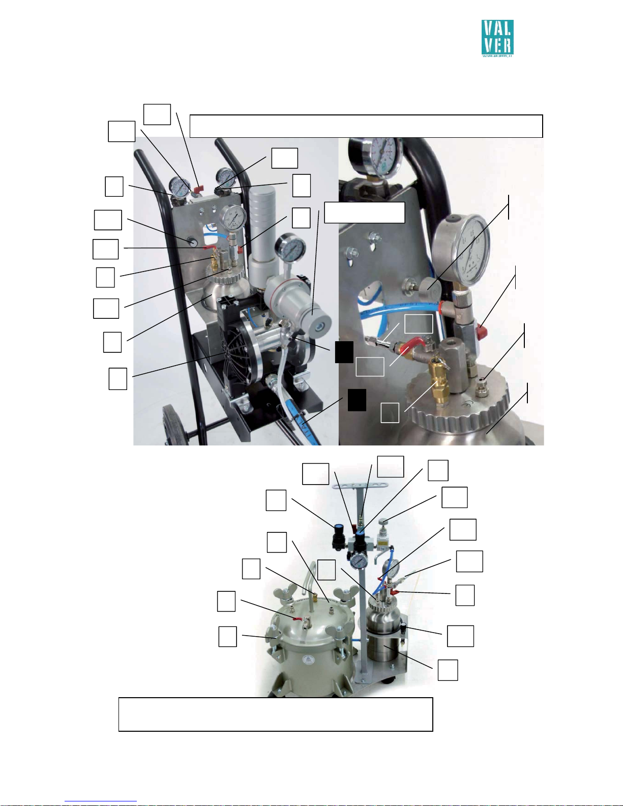
1. EQUIPMENT DESCRIPTION
The AIRBRUSH MANUAL EXTERNAL MIX EQUIPMENT is composed of two pumps.
The first pump is for resin and the type employed can be selected. The second pump for the
catalyser is a pressure tank.
A specially-prepared spray gun for combining and applying the two products. The
two products are always separated prior to their reaching the gun tip, where they are then
mixed by the air fan. This facilitates cleaning, as the equipment need not be cleaned at the
end of each task, and reduces solvent consumption considerably.
EQUIPMENTS for GLUES
Pressure tank or double diaphragm for resin, pressure tank for catalyst
10
11
12
9
2
Catalyst pump (pressure tank) (8)
1
7
5
4
2
8
3
13
resin
catalyst
2
12
10
9
15
10 L PRESSURE TANK option
1
5
7
8
resin catalyst
10
11
14
13
12
3
9
11
4
8 or 18 L PRESSURE TANK option
2
2

INSTRUCTIONS MANUAL
AIRBRUSH MANUAL EXTERNAL MIX EQUIPMENT
6
6
7
8
4
1
resin
catalyst
7
14
13
13
6
14
Catalyst regulator
Resin regulator
10
DOUBLE DIAPHRAGM option
for 2 or 4 spray guns
Option for 2 guns
Can incorporate sets of 2-8-18 L
pressure tanks and combined with a
double diaphragm pump
4
1
12
7
8
resin
catalyst
10
14
13
Resin REGULATOR
9
7
13
14
4
5
10
7
2 L PRESSURE TANK option
3
9
12
2
2
8
1
resin
catalyst
2
11
6
INSTRUCTIONS MANUAL
AIRBRUSH MANUAL EXTERNAL MIX EQUIPMENT
7
EQUIPMENT FOR POLYESTER, GEL COAT…
Pressure tank or double diaphragm for resin, pressure tank 2 L for catalyst
4
1
5
6
7
8
resin
10
DOUBLE DIAPHRAGM for RESIN – PRESSURE TANK for CATALYST option
2
14
13
12
11
9
8
9
1
4
Resin regulator
21
2
resin
catalyst
3
5
10 L RESIN PRESSURE TANK - 2 L RESIN PRESSURE TANK option
With micrometer valve (21)
21
12
11
2
10
8
9
25
catalyst
25
12
2
14
13
7
10

INSTRUCTIONS MANUAL
AIRBRUSH MANUAL EXTERNAL MIX EQUIPMENT
8
Application gun (15)
Exploded in page 21
1. Resin pump
2. Safety valve
3. Resin pump air stopcock
4.
Resin pump air control
5. Resin valve
6. Absorption
7. Air gun control
8. Catalyser pump
9. Catalyser pump air stopcock
10. Catalyser pump air control
11. Catalyser pump bleed
12. Catalyser valve
13. Intake air mixer adaptor
14. Mixer air stopcock
15. Gun
16. Catalyser head tube
17.
TRIMIX® mixer head
18. Gun trigger
19. Gun tip
20. Gun hook
21.
Micrometric valve
22. Air inlet spray pressure regulator
23. Material needle Regulator
24. Catalyser regulator
25. Catalyser outlet filter
17
16
18
20
19
15
24
23
22
Catalyser outlet filter (25)
Disassembled filter and filter holder
with mesh 100 (ref.FI00000000005)

INSTRUCTIONS MANUAL
AIRBRUSH MANUAL EXTERNAL MIX EQUIPMENT
9
1.1. Technical features:
You can choose different pumps depending on the mix and their percentage. The
characteristics depend on the models chosen.
For further information about the characteristics and features of the equipment to be
chosen, consult the Valver Air Speed pressure tank or dual-membrane pump general
catalogue and manuals. The manuals are supplied with the complete equipment.
2. TRANSPORT, HANDLING AND STORAGE.
The installation and set-up of the VALVER AIR SPEED, S.L., AIRBRUSH MANUAL
EXTERNAL MIX EQUIPMENT is carried out either by the manufacture’s staff or by
authorized distributors.
3. OPERATION
3.1. Safety rules
Before using the equipment it is important to know all the rules of use, operating conditions
and instructions for use.
SPEED AIR VALVER is not responsible if the operator fails to comply with the following
conditions and is not responsible for any negligence in using the equipment.
To avoid breaking pressure hoses or items to check before the equipment implementation:
x
All components are not worn or damaged.
x
Fittings and joints of the filters are very tight.
x
Use the machine with gloves, masks and eye protection and appropriate protective
clothing.
x
The products used in the machine may be highly inflammable. The equipment has not
been designed or manufactured for use in potentially explosive atmospheres, always use
the equipment in well-ventilated places; avoid any kind of activity which could cause
fire such as smoking, producing sparks, or shavings, or any electrical hazards. In
order to avoid the risk of sparks from electrostatic charges, the machine should be
adequately earthed.
x
Before starting, any cleaning or maintenance check electrical disconnection of the
equipment and the discharge pressure of the pneumatic elements.
x
Always use the solvent recommended by the product’s manufacturer for cleaning
the equipment.
x
Using the machine may cause intoxication from possible toxic fumes. The air extraction
system should function properly to ensure it is not used in a place where you can create
explosive atmospheres.

INSTRUCTIONS MANUAL
AIRBRUSH MANUAL EXTERNAL MIX EQUIPMENT
10
To avoid any risk of fire or explosion:
x
NO SMOKING, next to the machine.
x
NON-sparking.
In the case of fire or explosion, use extinguishers - do not use water.
Extinguishers:
Class ABC: Dry powder, for LIQUIDS AND GASES
Class E: CO
2
for ELECTRICAL PARTS
3.2. Starting-up equipment.
1. Make sure that the Mixer air stopcock (14), the Resin pump air stopcock (3)
(pressure tank only) and the Catalyser pump air stopcock (9) (pressure tank) are
closed.
2. Connect the air supply to the AIRBRUSH MANUAL EXTERNAL MIX EQUIPMENT’S
intake mixer air adaptor (13), which supplies the pumps and the gun (15).
3. Place the absorption (6) in the resin, in the case of dual-membrane units, or load the
tank, in the case of pressure tanks (closing correctly the Mixer air stopcock (14).
4. Open the Resin pump air stopcock (3) in the pressure tank and adjust the pressure
of the resin pump (1) using the resin pump air control (4).
5. Open the Catalyser pump air stopcock (9) in the pressure tank and adjust the
pressure of the catalyser pump (8) using the catalyser pump air control (10).
6. The gun (15) pressure can be adjusted using the air gun control (7).
7. Set the air gun control (7) to 0 bar to avoid splashing.
8. Open the resin valve (5) and adjust the resin pump air control (4).
9. Place the gun tip (19) in the nozzle of the resin test tube
(used for cleaning,
bleeding, recycling and calibration of mix percentage).
10. Squeeze the gun trigger (18) until resin begins to flow from the gun and the circuit
is loaded without air bubbles.
11. Close the resin valve (5) (dual membrane or pressure tank) before loading the
catalyser pump (8).
12. Make sure that there is no pressure in the catalyser pump (8) (pressure tank), keep
the catalyser air pump bleed cock (9) and open the Catalyser pump bleed (11)
(pressure tank).
13. Remove the top from the catalyser pump (8) (pressure tank) and fill the catalyser.
14. Replace the pressure tank top, making sure that it is properly closed.
15. Close the Catalyser pump bleed (11) and open the Catalyser pump air stopcock
(9) (pressure tank).
16. Adjust the catalyser pump air control (10) (pressure tank).
17. Open the catalyser valve (12).
18. Remove the TRIMIX® mixer head (17) from the gun (15). Once the TRIMIX® mixer
head (17) has been removed from gun (15), the equipment is ready for priming.
19. Place the TRIMIX® mixer head (17) in the nozzle of the catalyser test tube
(used for
cleaning, bleeding, recycling and calibration of mix percentage) in order to recycle
and prime the catalyser circuit.

INSTRUCTIONS MANUAL
AIRBRUSH MANUAL EXTERNAL MIX EQUIPMENT
11
20. Squeeze the gun trigger (18) until resin begins to flow from the TRIMIX® mixer
head (17) and there are no air bubbles in the circuit. The residual pressure in the
resin pump (1) will force resin to flow for a few seconds.
21. Replace the TRIMIX® mixer head (17) in the gun (15).
The AIRBRUSH MANUAL EXTERNAL MIX EQUIPMENT is pressurised with material and
ready for calibration.
Recommendations.
Clean the AIRBRUSH MANUAL EXTERNAL MIX EQUIPMENT thoroughly after use. Proper
maintenance will extend the equipment’s useful life.
Always use the solvent recommended by the product’s manufacturer for cleaning the
equipment.
The gun should be left immersed in cleaning solvent when not in use. The solvent must not
touch the air valve, in order that the nozzle remains clean.
Clean the outside of the TRIMIX® mixture head (17) frequently when working and leave the
gun (15) hanging vertically from the gun hook (20) when not in use. Avoid leaving the gun
(15) in a horizontal position, as this will lead to paint remains obstructing the catalyser
outlets.

INSTRUCTIONS MANUAL
AIRBRUSH MANUAL EXTERNAL MIX EQUIPMENT
12
3.3. Calibration.
1. Start-up the equipment.
2. Close the Mixer air stopcock (14), close the Resin pump air stopcock (3) and
close the Catalyser pump air stopcock (9).
3. Prepare 2 calibrated test tubes
. For maximum accuracy, place each test tube on
scales and weigh. If no scales are available, use the test tubes to calibrate by
volume.
4. Remove the TRIMIX® mixer head (17) with the catalyser head tube (16).
5. Open the Mixer air stopcock (14), open the Resin pump air stopcock (3) and
open the Catalyser pump air stopcock (9).
6. Open the resin valve (5).
7. Regulate the resin pressure to 1 bar with the resin pump air control (4) and the
user adjusts the resin or component A output for the application on a bad
coating surface and counting the lack of catalyst output to be considered
depending on the mix percentage (If f. e. the product mix percentage is two parts
A for one part B and it is only applied resin in this set-up, the user has to consider
that 33% less product is outputted. Afterwards it will be incorporated while
adding the catalyst when the calibration process has been completed. The
regulation is done by opening the material needle regulator (23) until
adjusting the desired product output. This can also be adjusted by changing the
flow of the available needles 0.8 – 1.0 – 1.3 – 1.5 – 1.8 – 2.0 and as well by
increasing or decreasing the pressure with the resin pump air control (4). Our
recommendation is to start with 1 bar and adjust by opening the material
needle regulator (23) up to a maximum of three rotations. Having reached
three opening rotations at 1 bar without having obtained the required flow, the
material pressure has to be increased in steps of 0.2 bar. Once you have reached
2 bar and go further on without getting the required flow, the needle valve has
to be replaced immediately by the superior one and the calibration process has
to be repeated starting again at 1 bar. When the final user has achieved the
desired quantity of the component A it has to be started the final calibration of
the catalyst or component B.
8.
For that open the catalyser valve (12) and adjust the catalyst output pressure
with the catalyser pump air control (10) starting for the first calibration like in
the beginning with the resin at 1 bar.
9. Position the gun tip (19) in the resin measuring cylinder and position the
dismantled TRIMIX® mixer head (17) in the catalyst measuring cylinder. Close
the spray pressure inlet with the air inlet spray pressure regulator (22).

INSTRUCTIONS MANUAL
AIRBRUSH MANUAL EXTERNAL MIX EQUIPMENT
13
10. After that press the gun trigger (18) and fill the measuring cylinders up to the
desired quantity.
11. Check the volume proportion or the material weight with a balance and adjust
the proportion with the catalyser pump air control (10) at the pressure tank or
with the catalyser regulator (24) of the pistol. In case of two-componentproducts application with a small mix ratio the machine is equipped with a
micrometric valve (21). To adjust the mixture proportions directly with the
micrometric valve, please follow the guidance table and the advices:
PRESSUREINLETPRESSURETANK
VALVEROTATIONS
0,5 0,6 0,7 0,8 0,9 1
1 0 0 0 0 0 0
2 2,1 2,6 3,4 3,7 4,7 5,2
3 5,4 6,2 7,3 8,1 9,1 10
4 8,2 9,9 11,3 12,9 14,3 15,6
5 12,1 13,5 15,4 15,9 17,1 17,8
6 16,4 18,6 21,9 23,1 25,4 26,7
7 20,8 24,8 28,7 30,4 32 33,2
8 25,7 30,2 34 36,6 39,2 42,4
9 33,6 40,2 44,7 46,9 50,1 53,8
10 48,7 54,4 59,7 64,2 69,6 72,6
This table facilitates and orientates only for the start-up procedure. Attention! It is neither an
orientation nor an exact formula, because these flows always may vary depending on viscosities, hose
length and material losses.
Advices
: After finishing step 6 and achieving the required quantity of component A it will be
proceeded to the final calibration of the catalyst or component B.
Therefore the flow per minute of the component A has to be controlled by a balance removing the
spray air from the pistol.
When we know the resin flow per minute selected by the user, for example 150g/min, we
have to multiply this with the catalyst or component B mix percentage expressed by the application
product manufacturer, for example 5% means 150 x 0.05 = 8g/min. Looking to the table we have two
consistent adjustment options.
Option 1. Feeding the pressure tank with the catalyser air pump control (10) with 0.5 bar and
turning the knob of the micrometric valve (21) 4 times starting at 0
Opción 2. . Feeding the pressure tank with the catalyser air pump control (10) with 0.8 bar and
turning the knob of the micrometric valve (21) 3 times starting at 0
If we aim for option 2 we get the more balanced valve regulation option, where the catalyst
pressure is closer to the resin pressure.

INSTRUCTIONS MANUAL
AIRBRUSH MANUAL EXTERNAL MIX EQUIPMENT
14
12. For the calibration adjustments follow the application product manufacturer
instructions. Repeat the calibration until getting the proportion as indicated by
the manufacturer.
Register the regulation parameters shown on the pages 14-15-
16 of this manual, paragraph SETTING UP EXTERNAL MANUAL MIX.
13. Close the mixer air stopcock (14), close the resin pump air stopcock (3) and
close the catalyser pump air stopcock (9) and recharge the deposits if
necessary.
14. Place the TRIMIX® mixer head (17) .
15. Open the mixer air stopcock (14), open the resin pump air stopcock (3) and
open the catalyser pump air stopcock (9) and the spray pressure with the air
inlet spray pressure regulator (22). Adjust the spray pressure according to the
nature of the product and user requirements with the air gun control (7).
16. Adjust the pressure with the air gun control (7) or with the spread regulator.
The AIRBRUSH MANUAL EXTERNAL MIX EQUIPMENT is calibrated and ready for use.
Recommendations.
Clean the AIRBRUSH MANUAL EXTERNAL MIX EQUIPMENT thoroughly after use. Proper
maintenance will extend the equipment’s useful life.
Always use the solvent recommended by the product’s manufacturer for cleaning the
equipment.
The gun should be left immersed in cleaning solvent when not in use. The solvent must not
touch the air valve, in order that the nozzle remain clean.
Clean the outside of the TRIMIX® mixture head (17) frequently when working and leave the
gun (15) hanging vertically from the gun hook (20) when not in use. Avoid leaving the gun
(15) in a horizontal position, as this will lead to paint remains obstructing the catalyser
outlets.

INSTRUCTIONS MANUAL
AIRBRUSH MANUAL EXTERNAL MIX EQUIPMENT
15
4. CLEANING AND MAINTENANCE
Cleaning.
1. Close the Mixer air stopcock (14), close the Resin pump air stopcock (3) and close
the Catalyser pump air stopcock (9).
2. Keep the resin valve (5) and the resin pump air control (12) closed.
3. Remove the absorption (6) and place in cleaning solvent.
4. Open the Catalyser pump bleed (11) (pressure tank), release the air an open the
cover of the catalyser pump (8) (pressure tank).
5. Fill the catalyser pump (8) (pressure tank) with cleaning solvent.
6. Follow steps 4 and 5 for pressure tank resin pumps (1).
7. Replace the catalyser pump (8) cover, making sure that it is properly closed.
8. Open the Mixer air stopcock (14), open the Resin pump air stopcock (3) and open
the Catalyser pump air stopcock (9).
9. Open the resin valve (5) and the resin pump air control (12).
10. Squeeze the gun trigger (18) until clean solvent –free of resin and catalyser residueis expelled.
11. Close the Mixer air stopcock (14), close the Resin pump air stopcock (3) and close
the Catalyser pump air stopcock (9).
12. Always leave the equipment PRESSURISED. Loaded with pressurized cleaning
solvent.
Maintenance.
1. Clean the TRIMIX® mixer head (17) frequently when in use.
2. Always leave the TRIMIX® mixer head (17) immersed in cleaning solvent. When left
unused for long periods, place in a tightly sealed recipient with solvent. This will
impede the evaporation of the solvent and the catalyser outlets becoming blocked
by any remaining residue.
3. Clean the equipment each day with the cleaning solvent recommended by the
manufacturer and which we applied to the resin pump (1) (dual membrane or
pressure tank) to avoid blockage from resin residue.
4. Clean the equipment each day with the cleaning solvent recommended by the
manufacturer and which we applied to the catalyser pump (8) (pressure tank) to
avoid blockage from the catalyser.
5. Check the gun, anti-pulsation chamber or absorption filters between the 1st and the
2nd cleaning.
6. Grease the exchange valves in dual membrane units ONCE PER WEEK when the
equipment is in use.
The equipment is to be subjected to an initial revision some 3 months after installation. This
check is to cover all the AIRBRUSH MANUAL EXTERNAL MIX EQUIPMENT’S spray
equipment, as well as the correct operation of all the equipment’s safety systems. If
everything is as it should be after the service check, further service checks are to be carried
out every six months until the end of the guarantee period. After the guarantee expires, the
frequency of service checks will be agreed with the client.

INSTRUCTIONS MANUAL
AIRBRUSH MANUAL EXTERNAL MIX EQUIPMENT
16
Periodic revisions undertaken during the guarantee period will be charged to the customer.
Periodic maintenance:
For EXTERNAL MIX EQUIPMENT spray equipment, change only used, dirty or old filters.
The equipment contains no other consumable components requiring periodic replacement.
The revisions to be carried out by the maintenance staff of the company responsible for
acquiring the AIRBRUSH MANUAL EXTERNAL MIX EQUIPMENT spray equipment are
aimed at verifying the correct operation of the equipment and the early detection of possible
problems. We recommend that such revisions be carried out at least once a week:
Preventive maintenance every 7 days:
Check air suplly unit.
Check air leakage of pneumatic circuit.
Check filters.
Preventive maintenance every 30 days:
Check purges and safety pneumatic valves.
If an abnormality is found during this preventive maintenance, take appropriate measures to
correct them.
5. SAFETY RULES
In the design and manufacture of equipment have been taken into account the essential
safety requirements for machine safety directive 98/37/EEC.
6. DISASSEMBLY CONDITIONS
When you stop using the machine, contact to VALVER AIR SPEED service.

INSTRUCTIONS MANUAL
AIRBRUSH MANUAL EXTERNAL MIX EQUIPMENT
17
MANUAL EXTERNAL MIX SET-UP CHART
EQUIPMENT IDENTIFICATION Nº:
PURCHASE DATE:
DISTRIBUTOR: C
ontact:
CUSTOMER:
Contact:
Customer phone:
Fax/e-mail:
Factory Testing:
Technical:
date:
Checking in customer:
Technical:
date:
Delivery Note No
MIX CHARACTERISTICS
Manufacturer: Fund Finishing
Product to: Solvent-based Water-based
Resin Type: (polyurethane, acrylic, polyester, gel coat, etc.)
A Component
Reference Viscosit
y
% Formula for TOTAL % Formula for RESIN
Resin
A
ccelerator
Diluent
Other
B Component
Reference Viscosit
y
% Formula for TOTAL % Formula for RESIN
Diluent
Catalyst
Other
Mix formula Comments:
Resin temperature
A
bsortion Viscosit
y
A
pplication Viscosity
ºC ºC
Catalyst temperature
A
bsortion Viscosit
y
A
pplication Viscosity
ºC ºC
Heater
Material
Set Tº Reached T
ª
Bel
t
ºC ºC
line ºC ºC
Heated hose ºC ºC
A
ir Heated hose ºC ºC
MANUAL EXTERNAL MIX SET-UP CHART
INSTRUCTIONS MANUAL
AIRBRUSH MANUAL EXTERNAL MIX EQUIPMENT
18
EQUIPMENT IDENTIFICATION Nº:
PURCHASE DATE:
DISTRIBUTOR: C
ontact:
CUSTOMER:
Contact:
MIX SETTING CHART
Resin model equipmen
t
Manometer scale
Catalyst model equipment Manometer scale
Gun model
External mix head mode
l
Nozzle type
Gun spray air pressure
Material
A
mbient temperature: ºC
A
mbient humidity: %
BEFORE CALIBRATING AFTER CALIBRATING
TEXT nº
Threads
nozlle
Regulator gun
needle laps
Resin
pump
pressure
Catalyst
pump
pressure
Dose
catalyst
(g./ml.)
Dose
resin
(g./ml.)
%
catalyst/resin
1
2
3
4
5
6
7
8
Comments:
TEXT 1
Piece dimensions
Weight part without appling g.
Weight part freshly applied g.
Weight part at 30 min g. Weight partat60 min g.
Drying
To contac
t
min.
In package min.
TEXT 2
Piece dimensions
Weight part without appling g.
Weight part freshly applied g.
Weight part at 30 min g. Weight partat60 min g.
Drying
To contac
t
min.
In package min.

INSTRUCTIONS MANUAL
AIRBRUSH MANUAL EXTERNAL MIX EQUIPMENT
19
MANUAL EXTERNAL MIX SET-UP CHART
TEXT 3
Piece dimensions
Weight part without appling g.
Weight part freshly applied g.
Weight part at 30 min g. Weight partat60 min g.
Drying
To contac
t
min.
In package min.
TEXT 4
Piece dimensions
Weight part without appling g.
Weight part freshly applied g.
Weight part at 30 min g. Weight partat60 min g.
Drying
To contac
t
min.
In package min.
TEXT 5
Piece dimensions
Weight part without appling g.
Weight part freshly applied g.
Weight part at 30 min g. Weight partat60 min g.
Drying
To contac
t
min.
In package min.
TEXT 6
Piece dimensions
Weight part without appling g.
Weight part freshly applied g.
Weight part at 30 min g. Weight partat60 min g.
Drying
To contac
t
min.
In package min.
TEXT 7
Piece dimensions
Weight part without appling g.
Weight part freshly applied g.
Weight part at 30 min g. Weight partat60 min g.
Drying
To contac
t
min.
In package min.
TEXT 8
Piece dimensions
Weight part without appling g.
Weight part freshly applied g.
Weight part at 30 min g. Weight partat60 min g.
Drying
To contac
t
min.
In package min.

INSTRUCTIONS MANUAL
AIRBRUSH MANUAL EXTERNAL MIX EQUIPMENT
20
VISCOSITY EVOLUTION IN ACCORDANCE WITH SOLVENT-BASED PAINTS TERMPERATURE
We recommend reducing resin viscosity in order to obtain optimum curing of both the
mixture and the final finish. The viscosity and the temperature can be reduced without
adding emission-increasing solvents to the mixture, thus ensuring compliance with the
applicable legislation.
Temperature (ºC)
CF4 VISCOSITY en seconds
2º 4º 6º 8º 10º 12º 14º 16º 18º 20º 22º 24º 26º 28º 30º 32º 34º 36º 38º 40º
27 26 24 23 22 21 21 20 19 18 18 17 17 16 15 15 14 14 14 14
33 31 29 27 26 25 23 22 21 20 19 18 18 17 16 16 15 15 14 14
39 36 34 32 30 28 26 24 23 22 21 20 19 18 17 17 16 15 15 14
46 42 39 36 34 31 29 27 26 24 23 22 21 19 18 17 17 16 15 15
54 49 45 41 38 35 32 30 28 26 24 23 21 20 19 18 17 17 16 15
58 51 47 43 40 36 33 31 29 27 25 23 21 20 20 19 18 17 16 16
61 55 50 46 42 38 35 32 30 28 26 24 22 21 20 19 18 17 16 16
69 63 56 52 46 42 39 35 32 30 28 25 24 23 21 20 19 18 17 16
77 69 62 55 50 46 41 38 35 32 29 27 25 24 22 21 19 18 17 16
84 74 67 61 54 50 44 40 36 34 30 28 26 25 23 22 20 18 17 16
95 84 75 66 60 54 48 44 40 36 33 30 28 26 24 22 20 19 18 17
104 92 81 73 65 58 52 46 42 38 35 31 29 27 24 23 21 20 19 18
112 100 88 76 69 62 54 49 44 40 36 32 30 27 25 23 21 20 19 18
122 108 90 85 75 66 59 53 47 42 38 35 31 28 26 24 22 21 19 18
132 120 102 90 80 70 63 55 50 44 40 36 33 30 27 25 23 22 20 18
142 124 108 95 84 74 65 58 52 46 41 37 34 31 27 25 23 22 20 18
152 132 119 101 90 80 69 61 54 48 43 38 35 31 28 26 24 23 21 18
164 140 123 106 94 83 73 64 56 50 45 40 36 32 29 27 24 23 21 19
If viscosity is 26 s at 18ºC, a drop of 10ºC will produce a viscosity of 34 s, while a rise to 40ºC will produce a
viscosity of 15 s.

INSTRUCTIONS MANUAL
AIRBRUSH MANUAL EXTERNAL MIX EQUIPMENT
21
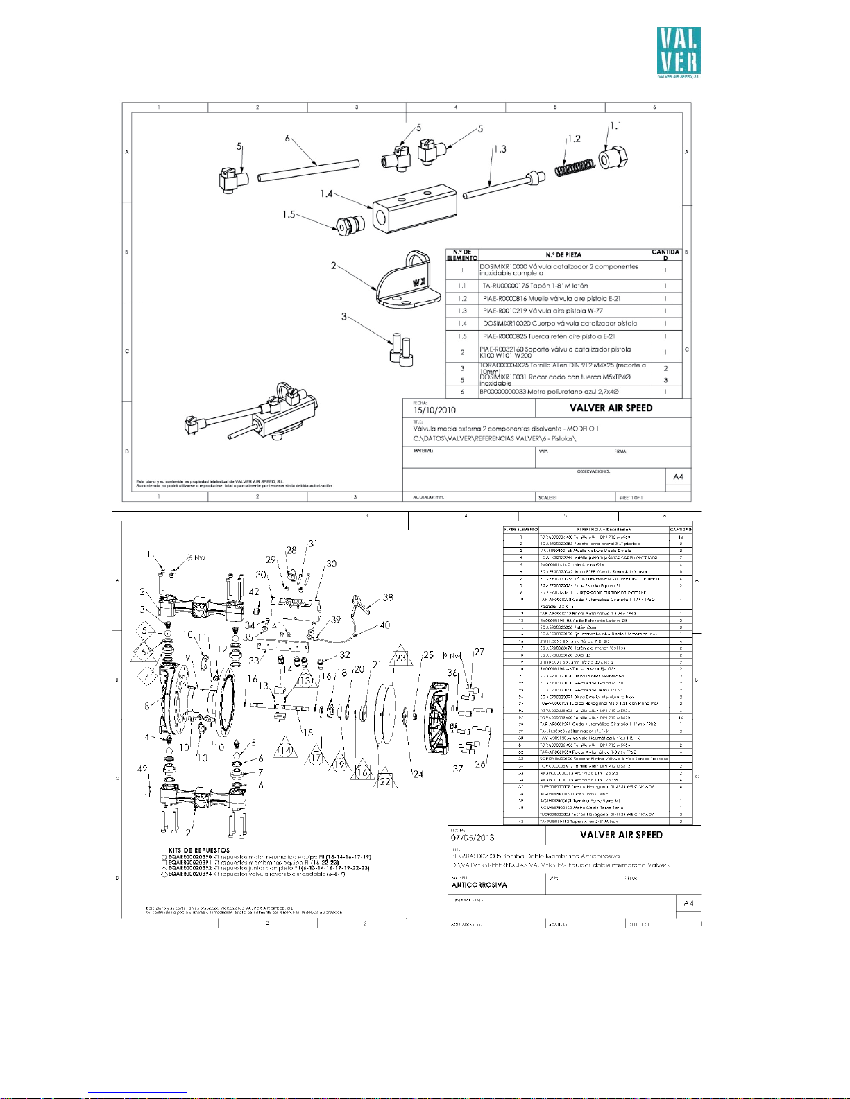
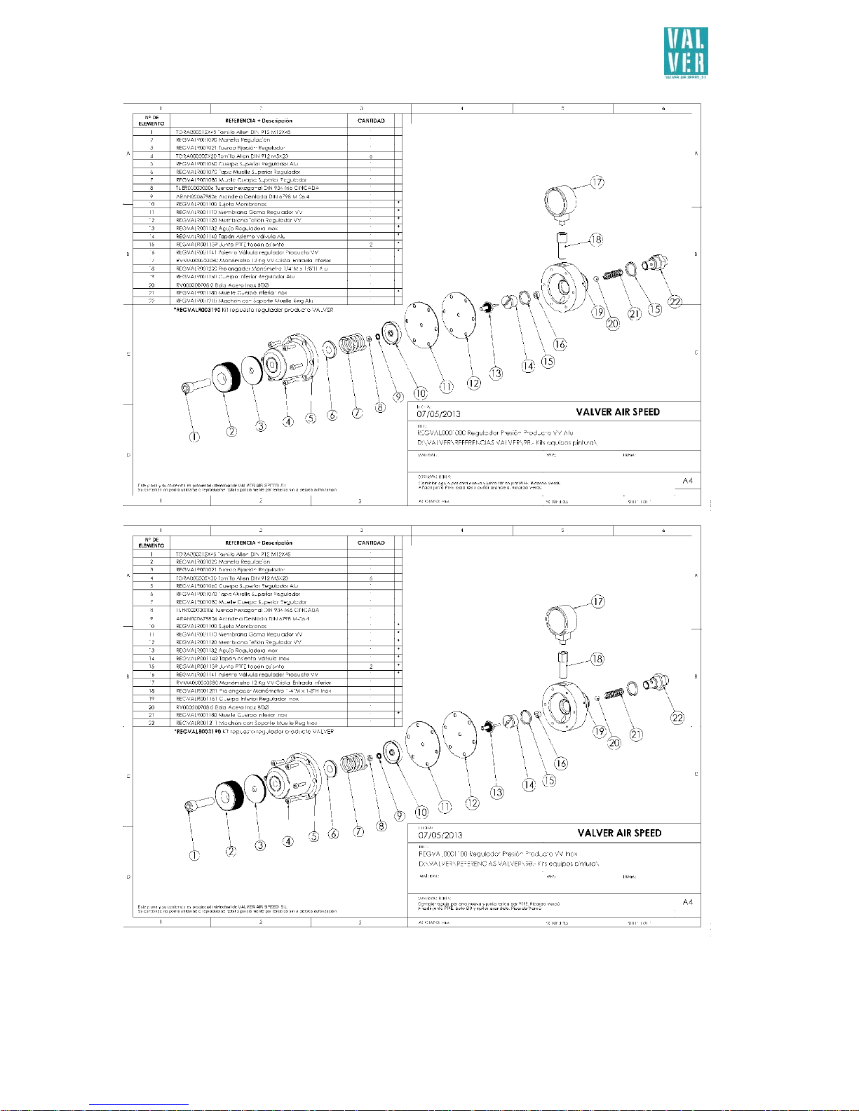
APPLICATION GUN EXPLODED

INSTRUCTIONS MANUAL
AIRBRUSH MANUAL EXTERNAL MIX EQUIPMENT
22
INSTRUCTIONS MANUAL
AIRBRUSH MANUAL EXTERNAL MIX EQUIPMENT
23
INSTRUCTIONS MANUAL
AIRBRUSH MANUAL EXTERNAL MIX EQUIPMENT
24
INSTRUCTIONS MANUAL
AIRBRUSH MANUAL EXTERNAL MIX EQUIPMENT
25
MAINTENANCE OPERATIONS
OPERATION
PERIODICITY
maintenance personal
DAILY WEEKLY MONTHLY* SEMIANNUAL*
*
INDICATE THE DATE.
 Loading...