

Page 1

INSTALLATION, OPERATION AND MAINTENANCE MANUAL (IOM)
Model 5500 Pilot Operated
Pressure Relief Vent
w/ Pipeaway Connection
IOM-5500
01-17
ISO Registered Company
SECTION I
I. DESCRIPTION AND SCOPE
The maintenance of this Pilot Operated Vent Valve
(POVV) should only be done by qualified valve
technicians. It is important that the technician be
familiar with the API and corporate standards,
corporate safety policies and the relief vent
manufacturer requirements. When repair services
are performed by an outside company, the company
needs to be a Cashco factory authorized repair
center which specializes in low pressure venting
devices.
SECTION II
II. VALVE DESIGN AND FUNCTION
The Model 5500 Pilot Operated Vents are used on
liquid storage tanks and other process vessels or
systems to prevent structural damage due to excess
internal pressure. This excess pressure is vented
out through a pipeaway connection.
Storage tanks are pressurized when liquid is
pumped in, compressing the existing vapor or
when increasing temperature causes increased
evaporation or expansion of existing vapor.
Conversely, a vacuum may be created when fluid
is pumped out or as atmospheric temperature
decreases. To prevent structural damage, vapor
must be allowed to escape or enter the tank at a
specified flow rate. The volume rate of venting is
dependent on the tank size, displacement rate and
the flash point of the fluid. See API Standard 2000
for procedures to determine venting requirements.
A pilot operated relief vent has two principal
advantages over other relief vent designs:
1. Bubble tight shutoff up to 100% of set point.
2. Full open capacity for pressure relief is achieved
within 10% above set point.
For information on repair centers in your area,
please contact:
Valve Concepts, Inc.
%Cashco, Inc.
607 West 15th Street
Ellsworth, KS 67439-0006
(785) 472-4461 (Phone)
(785) 472-3539 (Fax)
Thus the vent valve is capable of operating at
pressures closer to the maximum allowable
working pressure of the tank. Operating at higher
pressures reduces evaporation and total venting
volume, thereby reducing product loss and the cost
of handling emissions.
Each application must be reviewed to ensure material compatibility with all metal and soft good
components with the service conditions. The pallet
assembly, wetted components and tubing are 316
SST. Diaphragm material is FKM, unless specified
otherwise.
The pilot valve is factory set to comply with the
specifications on the purchase order. The adjustable pressure range is a function of the installed
spring and will be stamped on the metal nameplate.
The set point pressure maybe changed within the
design parameters of the spring while installed on
line or in a maintenance shop. See Section IX
for setting and testing procedures.
This manual is intended to provide recommended
procedures and practices for installation, operation
and maintenance of the Model 5500 POVV. Although this manual cannot cover all possible contingencies, these guidelines will provide safe and
reliable pilot valve performance.
Page 2
SECTION III
III. SAFETY WARNINGS
WARNING
Warning: Before beginning any relief vent inspection
or maintenance, carefully read and understand the
information in this manual. If there are any questions
concerning the information in this manual, please
contact the factory or an authorized repair center
before proceeding.
The 1/2” OD SST pilot valve sensing line must be
kept open and unobstructed to ensure that the pilot
“senses” the actual tank pressure. For applications
where tank vapors may condense or polymerize in
the sensing tubing or the pilot valve, a nitrogen purge
may be required to prevent internal obstruction of the
tube. Consult the factory for recommendations.
Tank or system protection is the primary function of
the Pilot Operated Vent Valve (POVV). It must be
selected to meet the total pressure flow requirements
within the maximum allowable working pressure
of the system on which it is installed. Consult API
Standard 2000 for tank protection sizing procedures.
Improperly specified relief vents may result in
structural damage to the tank or system, and can
cause severe personal injury or death.
In the event of a diaphragm failure, the Model
5500 will vent pressure to the pipeaway connection
causing the pressure relief valve to fail in the OPEN
position. The vent will now function like a weight
loaded vent under this condition with a lower set
point. Consult the factory for any questions related
to this over-pressure condition.
CAUTION
DO NOT attempt to change pressure set point beyond
the limit specified on the nameplate..
CAUTION
DO NOT attempt to remove the vent from the tank or
process vessel without fi rst bleeding all pressure from
the system. ALTERNATIVE MEANS OF PRESSURE
RELIEF MUST BE PROVIDED WHEN THE VENT IS OUT
OF SERVICE.
After isolating the relief vent, bleed all pressure
from both main and pilot valve before removing the
Model 5500 POVV.
NOTE: Both the pilot valve and main valve are
exposed to the process vapors. Observe all
plant procedures and Material Safety Data Sheet
recommendations before inspecting, adjusting or
servicing any components.
The vent on the spring bonnet of the pilot must
be clean and unobstructed for proper and safe
operation of the valve.
IV. SHIPPING, INSPECTION AND
STORAGE
The pressure relief vent is carefully packaged to
prevent damage or contamination during shipping.
Inspect the equipment when it is received and
report any damage to the carrier immediately. The
POVV should be stored in a clean environment with
all the protective flange covers in place to prevent
intrusion of foreign materials. If there are indications
of physical damage or internal contamination, the
valve may need to be disassembled, cleaned and
inspected prior to installation.
2
SECTION IV
Lifting brackets may be provided on the main valve
for lifting and handling. To avoid damage to the
lower flange surface, rest the vent on a soft clean
gasket material until it is ready to be installed. DO
NOT store the POVV directly on the ground.
IOM-5500
Page 3
V. INSTALLATION
SECTION V
The Model 5500 POVV is a precision device that
must be handled carefully to ensure seat tightness.
WARNING
The vent must be installed in a vertical position. The
tank nozzle on which the vent is mounted should have
the same nominal diameter as the venting device. It
is recommended that the tank nozzle flange face be
within 1 degree of horizontal for best performance of
the venting device.
1. At installation, the POVV should be carefully
lifted into position using the lifting brackets on
the body. Use the case assembly (114,116)
to help align the body directly over the tank
nozzle. DO NOT use the pilot valve or pickup
line to pull the POVV into position.
2. Aluminum body vents should be mated to flat-
faced 125# ASME flanges. Mating flanges
should be flat within 0.020” and clean; free of
scratches, corrosion and tool marks. A full
faced gasket is recommended.
3. Install the flange gasket on the nozzle face.
Use either a full faced or ring gasket for raised
face flanges. Ensure that the gasket material is
suitable for the service. See Table 1 for gasket
dimensions.
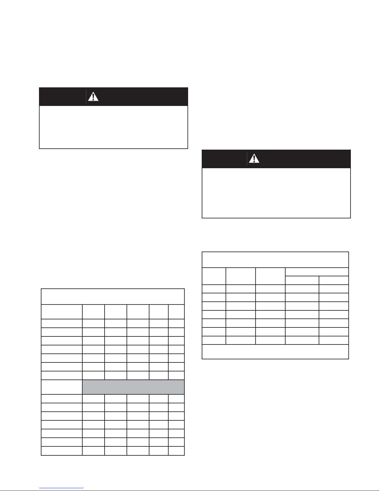
Table 1
Body Flange Gasket Dimensions
CS, SST
150# ASME RF
2’ 4.12 2.38 -- -- --
3” 5.38 3.50 -- -- --
4” 6.88 4.50 -- -- --
6” 8.75 6.62 -- -- --
8” 11.00 8.62 -- -- --
10” 13.38 10.80 -- -- --
12” 16.12 12.80 -- -- --
Alum w/ 125#
ASME FF
2” 6.00 2.00 4.75 .75 4
3” 7.50 3.00 6.00 .75 4
4” 9.00 4.00 7.50 .75 8
6” 11.00 6.00 9.50 .88 8
8” 13.50 8.00 11.75 .88 8
10” 16.00 10.0 14.25 1.00 12
12” 19.00 12.00 17.00 1.00 12
O.D. I.D. B.C. Hole Qty
4. Center the gasket within the bolt circle of the
tank nozzle flange.
5. Lubricate all studs and nuts with an appropriate
thread lubricant. If stainless steel studs and
nuts are required, use an anti-seize lubricant
such as moly-disulfide.
6. Remove flange protective cover and carefully
set the POVV down on the gasket and face of
the nozzle flange.
WARNING
Minimum clearance between tank roof and vacuum
inlet port must be at least equal to the vents’
nominal flange bore. Tank nozzle bore must be
greater than or equal to vent inlet flange bore. Inlet
piping loads must be supported by appropriate
structural supports, NOT by the vent body.
7. Install lockwashers and nuts. Tighten nuts to
half the recommended torque value using an
alternating crossing pattern. See Table 2.
Table 2
Recommended Minimum Torque Values *
Size
2” 4 5/8”-11 31 81
3” 4 5/8”-11 43 106
4” 8 5/8”-11 29 68
6” 8 3/4’10 51 101
8” 8 3/4”-10 78 142
10” 12 7/8”-9 75 138
12” 12 7/8”-9 93 179
* Torque values are based on a gasket factor m = 3.5,
gasket factor y = 4000 psi, operating pressure = 30 psi
Qty
Holes
Bolt
(UNC)
Torque (lb-ft)
Raised Face Flat Face
8. Make sure that the gasket is compressed evenly
and the flanges are not distorted.
NOTE: Misalignment of flange faces will
cause bending stresses at the flange and may
damage flange joint. Refer to Addendum-A on
pages 16 and 17.
9. Finish tightening nuts to the point that no
additional rotation occurs.
IOM-5500
3
Page 4
SECTION VI
VI. PILOT MAINTENANCE
A. General:
1. Maintenance procedures herein after are
based upon removal of the pilot/vent valve
unit from the vessel/piping where installed.
2. Owner should refer to owner’s procedures
for re mov al, handling and cleaning of
non re us able parts; i.e. gaskets, suitable
solvents, etc.
3. All indicated Item Numbers that are with
respect to the Pilot Assembly will be in
pa ren the sis and un der scored; i.e. (29). All
Item Numbers that are with respect to the
Main Valve are not un der scored; i.e. (108).
B. Separation from Main Valve and Disassembly:
1. Disconnect sense tube (124) from fittings
(123) and (122). Also, disconnect the
discharge tube (125) from tube connectors
(122). Remove the pilot valve assembly
from the nipple (121) by rotating the pilot
body (01) CCW.
2. Secure pilot body (01) in vise with ‘sensing”
port facing front. Disconnect tubing (34)
from connectors (32),(33).
diaphragm case (22) clears top of spring
button (21). Set assembly aside.
6. Lift range spring (20) and spring button
(21) up and set aside.
7. Insert a tool in slot in the top of stud (18)
to prevent stud rotation. Rotate nut (19)
CCW to remove nut and spring guides
(17).
8. Remove sense pressure ring (15), sense
support plate (16), sense diaphragm (14)
and diaphragm case spacer (13).
9. Remove top bolt gasket (07), and sense
diaphragm spacer (12).
10. Remove support plate-boost (11), boost
diaphragm (10), boost diaphragm spacer
(09) and another bolt gasket (07).
FOR Pilot with Pressure > 3.2 psig:
remove boost pressure ring (36).
11. Rotate 7/16” hex head cap screws
(04) CCW to remove. Lift up on lower
diaphragm case (03) to remove lower case
and gasket (02). NOTE the alignment of
the four bolt holes and the sense hole in
case (03) with the holes in the body (01).
3. Paint or embed a set of match marks
between upper case (22), spacer (13) and
lower case (03) along flanged area. Note
the location of 1/8” NPT tap from elbow (33)
in relation to body sensing port and straight
connector (32).
WARNING
SPRING UNDER COMPRESSION. Prior to re mov ing
flange bolts, relieve spring com pres sion by backing
out the adjusting screw. Failure to do so may result
in flying parts that could cause personal injury.
4. Rotate the closing cap (29) CCW for
removal. Loosen the adjusting screw nut
(27) two revolutions. Rotate Adjusting
screw (28) CCW and remove.
5. Remove diaphragm case nuts (19),
flat washers (25) and cap screws (26).
Grasp spring bonnet (23) and lift up until
4
12. Grasp spindle stud (18) and lift upwards to
extract the spindle assembly (06) from the
body (01). Remove seal diaphragm (08)
from spindle. With a pick type tool lift out
seat o-ring (05).
13. Rotate jam nut (27) CCW two rotations
and remove blowdown needle (28) from
body (01). Replace with new O-ring (30).
14. Inspect parts and replace if parts show
signs of wear. Clean parts with suitable
cleaner.
C. Re-assembly:
1. Insert new seat o-ring (05) in the bottom
of the spindle assembly. Place spindle
assembly inside the body cavity, threaded
end up. Slide a new seal diaphragm over
threaded end of spindle and position it
on top of the body. Align holes in seal
diaphragm with holes in body.
IOM-5500
Page 5

2. Position new body gasket (02) on top of
the seal diaphragm, align gasket holes.
DO NOT cover sensing hole in the
body.
3. Align holes in the lower diaphragm case
(03) with body (01) and place the case
on top of the gasket. DO NOT cover
sensing hole. Use cap screws (04) to
secure lower diaphragm case (03) to the
body. (01). Tighten to 10-15 ft. lbs.
4. Slide one bolt gasket (07) and boost
diaphragm spacer (09) over threaded end
of spindle (18).
13. Lower the upper diaphragm case (22)
/ spring bonnet (23) assembly over the
spring (20), allow to rest on the pressure
ring (15). (Ensure alignment of match
marks per previous B 3.)
14. Install diaphragm case screws (26), flat
washers (25), and nuts (19) and tighten.
15. Apply a light coat of Bostik Never-Seez to
threads of blowdown needle (28). Thread
completely into body until the nut (27)
contacts the body (01) and then back
out two rotations. Rotate nut (27) CW to
secure nut tight.
5. Place another bolt gasket (07), the boost
diaphragm (10), and the support plateboost (11) on spindle stud (18). Align bolt
holes for all parts.
FOR Pilot with Pressure > 3.2 psig:
install boost pressure ring (36).
6. Install sense diaphragm spacer (12) and
the last bolt gasket (07) on spindle stud
(18).
7. Place the diaphragm case spacer (13) on
top of the diaphragm (10), (or on top of the
boost pressure ring (36)) and align match
marks per previous B 3.
8. Install a new sense diaphragm (14) on
spindle stud (18) and align the bolt holes
with the boost diaphragm (10) and spacer
(13).
9. Stack the sense support plate (16) and
the spring guides (17) over end of spindle
stud (18)
16. Reinstall adjusting screw (28) and jam nut
(27) in top of spring bonnet (23). Install
closing cap (29).
17. Refer to Section IX for Calibration and
Testing.
18. Install pilot body assembly on nipple
(121) tight with CW rotation. Ensure the
sense tube connector (122) of the pilot
valve assembly is directly above sensing
tube connector (123) of the main valve
assembly.
19. Reconnect tubing (34) to fittings (32), (33)
and tubing (124) to fittings (123),(122).
Then, reconnect discharge tube (125) to
fitting (122).
10. Install and tighten nut (19) to secure all
parts. (Check alignment of the bolt holes
around the circumference.)
11. Position the range spring (20) and spring
button (21) on the spring guides (17).
12. Place pressure ring (15) on top of
diaphragm (14). Recheck alignment of
bolt holes.
IOM-5500
5
Page 6

VII. VENT VALVE MAINTENANCE
CAUTION
SECTION VII
Actuator Diaphragm Replacement:
a. Paint or embed a set of match marks
between upper case (116) and lower case
(114) along flanged area.
If the vent valve must be removed from the tank for any
reason, make sure that all pressure has been released
before the flange fasteners are loosened. Refer to your
company procedures before venting the tank pressure
and when handling toxic or otherwise hazardous
materials. Observe all standard safety precautions
as specified on Material Safety Data Sheets for the
product(s) in the system while removing the valve and
during the repair.
A. General:
1. The Model 5500 POVV does not require
routine lubrication or adjustments. It should
be checked periodically, at least twice a
year, to confirm that the vent is functioning
properly and that the set point is correct.
2. The pilot valve is designed to function in a
fail-safe manner. The failure of a seal or a
diaphragm will cause pressure to be vented out through a pipeaway connection; the
resulting loss in pressure will cause the
main valve to open under rising pressure.
3. Periodic inspection for seat tightness
should be done to ensure compliance with
local air pollution control requirements. If
the pipeaway connection relieves to the atmosphere, this maybe accomplished with
a gas detector calibrated for the principle
product in the system.
4. The vent valve will need to be removed
from the tank for inspection of diaphragms,
gaskets and seals. When this is done, the
vent must be handled carefully using the
lifting brackets (119) and the body.
5. The main and pilot valve housings, bodies,
pallet assembly and other components are
exposed to the process vapor.
B. Disassembly:
1. Disconnect the tubing connections (pilot to
main Valve) (123, 124, 125 and 122) and
remove the pilot by rotating the pilot body
(01) assembly CCW from nipple (121).
6
b. Loosen and remove nuts (118) and
cap screw (117).
c. Lift up and remove the upper case
(116) assembly and set aside. Remove
joint tape (130) and diaphragm (128).
NOTE: To continue with disassembly skip to Pressure Pallet Diaphragm Replacement below.
d. Replace with new parts (130 and 128).
Position and align bolt holes in the circumference of the diaphragm with the holes in
the lower case (114).
e. Reposition upper case assy (116) on
diaphragm (128). Align marks made in
step (a.) above.
f. Install cap screws (117) and nuts (118)
and tighten.
g. Install pilot body assembly on nipple
(01) tight with CW rotation. Ensure straight
connector (122) of the pilot valve assembly
is directly above sensing tube connector
(123) of the main valve assembly.
h. Reconnect tubing (124) to fittings
(123),(122). Then, reconnect the discharge tubing (134) to fitting (31) and
sense tube connector (132) Refer to Section IX for Calibration and Testing.
Pallet Diaphragm Replacement:
(Disassembly continues from c. above)
a. Paint or embed a set of match marks
between cover (111) and pipeaway body
(101).
b. Rotate cover nuts (112) CCW and re-
move. Grasp the lower and upper case
assembly (114,116) and lift straight up to
remove cover (111).
NOTE: Support plate (127) will also lift out
of pipeaway body (101). Pressure pallet
stem(106) assembly will remain on seat
ring (102).
IOM-5500
Page 7
c. Lay the whole upper case assembly
aside on a flat surface.
d. Lift pressure pallet stem assembly
(104) out of the pipeaway body (101).
Carefully secure stem (104) in a vise, oriented such that the pallet (106) assembly
is directed upwards.
e. Remove lock nut (109), diaphragm
retainer plate (108), diaphragm (107), pallet (106) and stiffner plate (105) from stem
(104).
To Remove Pressure Pallet Seat Ring:
NOTE: For replacement of integral or
pressed in seat rings, please contact factory.
Paint or embed a set of match marks be-
tween the seat ring (101) and the inside of
the body.
n. Rotate bolts (103) CCW and remove.
Place a wrench on the milled flats of the
pallet guides (110), rotate CCW to remove.
Mark location of guides on the edge of seat
ring (102) for reference at re-assembly.
f. Inspect and clean seat ring (102).
Check seat surface for any nicks, corrosion, pitting or product build up. Seat surface must be clean and smooth for vent to
perform properly. (Continue with step j.
unless changing gasket (49)).
To Remove Adapter Gasket: steps (g - i).
g. Paint or embed a set of match marks
between cover (111) and lower case
adapter assy (114).
h. Loosen and remove adapter bolts
(115). Lift cover (111) up and over support
plate (127). Remove and replace adapter
gasket (113).
i. Re-install cover (111) and align match
mark from g. above. Install adapter bolts
(115). Tighten securely.
j. Re-install stiffner plate (105) and pallet
(106) on stem (104). NOTE:Apply small
amount of TFE lubricant around the center
opening (top surface) of the pallet (106).
k. Place a new diaphragm (107) on the
pallet (106). NOTE: Apply small amount
of TFE lubricant around the center opening
(top surface) of the diaphragm (107).
l. Install the diaphragm retainer plate
(108) and nut (109).
m. Remove stem (104) assembly from
vise.
CAUTION
The pipeaway body (101) is no longer fastened
securely to the body (100) and could fall and cause
severe personal injury and material damage.
o. Lift up to remove seat ring (102) and
joint tape (130). (There is no tape on integral or pressed in seat rings.) Inspect
guides (110) and inside of the body cavity for any corrosion or product build-up.
Clean all parts as necessary. Seat surfaces must be clean and smooth for diaphragm and pallet to seal properly.
p. Install new joint tape (130). Align
match marks for seat ring (101) with
body, place seat ring back in body, resting on joint tape. Re-install pallet guides
(112) around the seat ring as previously
marked. Install bolts (103). Tighten bolts
(102) and guides to 15 ft. lbs. (20.3 Nm).
q. Place stem/pallet (104/106) assem-
bly back on seat ring (102).
r. Place a piece of joint tape (130) on
face of pipeaway body. Position pressure
cover (111) on pipeaway body. Align
match marks for cover and pipeaway
body. Install cap screws (112) to secure
cover to pipeaway body.
s. Insert small end of support plate
(127) down through the hole in the center
of the lower case (114) until it slides over
the top of the pressure stem (104).
IOM-5500
7
Page 8

t. Install new piece of joint tape and dia-
phragm (130 and 128). Position and align
bolt holes in the circumference of the diaphragm with the holes in the lower case
(114).
v. Install pilot body assembly on nip-
ple (121) tight with CW rotation. Ensure
straight connector (122) of the pilot valve
assembly is directly above sensing tube
connector (123) of the main valve assembly.
u. Reposition upper case assy (116) on
diaphragm (128). Align match marks made
in step B. 1. a. previous. Install cap screws
(117) and nuts (118) and tighten.
w. Reconnect tubing (34) to fittings (32),
(33) and tubing (124) to fittings (123),(122),
and tubing 125 to fittings (122).
SECTION VIII
VIII. ORDERING INFORMATION
NEW REPLACEMENT UNIT vs PARTS "KIT" FOR FIELD REPAIR
To obtain a quotation or place an order, please retrieve the Serial Number and Product Code that was stamped
on the metal name plate and attached to the unit. This information can also be found on the Bill of Material
(“BOM”), a parts list that was provided when unit was originally shipped. (Serial Number typically 6 digits).
NEW REPLACEMENT UNIT:
Contact your local Cashco, Inc., Sales Rep re sen ta tive with the Serial Number and Product code. With
this information they can provide a quotation for a
new unit including a complete description, price
and availability.
CAUTION
Do not attempt to alter the original construction of any
unit without assistance and approval from the factory.
All purposed changes will require a new name plate
with appropriate ratings and new product code to
accommodate the recommended part(s) changes.
PARTS "KIT" for FIELD REPAIR:
Contact your local Cashco, Inc., Sales Rep re sen ta tive with the Serial Number and Product
code. Identify the parts and the quantity required
to repair the unit from the “BOM” sheet that
was provided when unit was originally shipped.
NOTE: Those part numbers that have a quantity indi-
cated under "Spare Parts" in column "A” reflect
minimum parts required for inspection and
rebuild, - "Soft Goods Kit". Those in column “B”
include minimum trim replacement parts needed
plus those "Soft Goods" parts from column "A".
If the "BOM" is not available, refer to the crosssectional drawings included in this manual for
part identification and selection.
A Local Sales Representative will provide
quotation for appropriate Kit Number, Price
and Availability.
The contents of this publication are presented for informational purposes only, and while every effort has been made to ensure their accuracy, they are not to be
construed as warranties or guarantees, express or implied, regarding the products or services described herein or their use or applicability. We reserve the right to
modify or improve the designs or specifications of such product at any time without notice.
Cashco, Inc. does not assume responsibility for the selection, use or maintenance of any product. Responsibility for proper selection, use and maintenance of any
Cashco, Inc. product remains solely with the purchaser.
8
IOM-5500
Page 9
SECTION IX
IX. PRESSURE CALIBRATION AND
TESTING PROCEDURE FOR PILOT
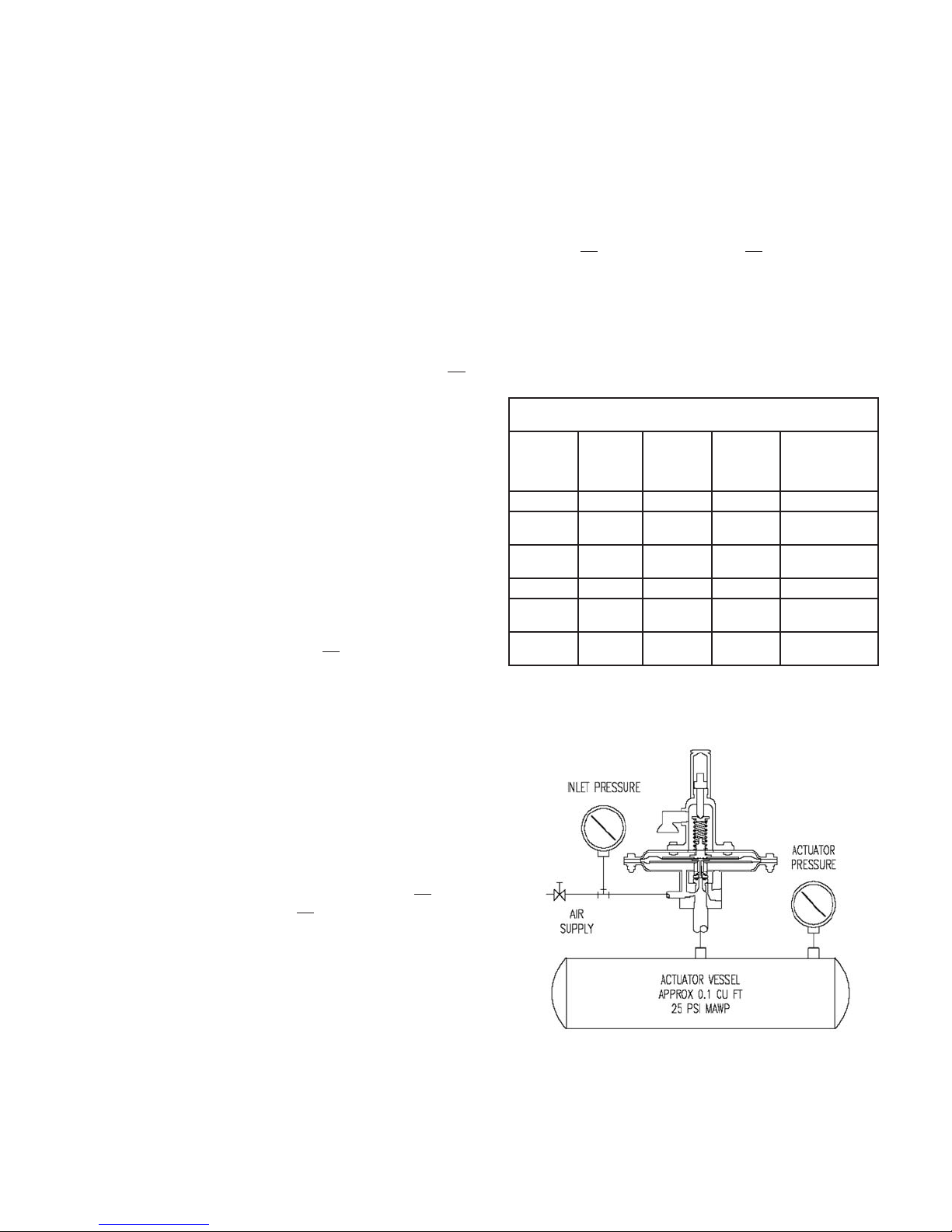
1. To determine set pressure, slowly increase
the pilot inlet pressure. Simulated actuator
pressure will rise with inlet. As set pressure
is approached, the actuator pressure will begin to decrease. Continue to increase the
inlet pressure slowly until the actuator pressure is 90% (+/- 10%) of the inlet pressure.
This is the set pressure.
2. Rotate the set pressure adjusting screw (28)
CW to increase set pressure or CCW to decrease set pressure. Continue to rotate the
adjusting screw and repeat the test per Step
1 previous until the specified set pressure is
achieved.
3. To determine reseat pressure, slowly decrease the inlet pressure and the actuator
pressure will begin to increase. Reseat occurs when the actuator pressure equal the
inlet pressure.
4. The difference between set and reseat
pressure,”blowdown”, can be adjusted with
the blowdown needle (28). Maximum clockwise rotation provides rapid relief valve opening, “snap action”’ and maximum blowdown.
Standard blowdown, unless otherwise specified is 7 - 10% below set pressure.
7. A small interaction occurs between set
pressure and blowdown adjustments. Readjustment of both may be required until
the specified set pressure and blowdown
are achieved. After completion, lock both
screws and locknuts and replace closing cap
(29) on adjusting screw (28).
8. Hold the valve at the set pressure while
preforming a soap bubble test of all bolted,
flanged and threaded connections.
9. Refer to Table 3 for standard setting Specifications.
SETTING SPECIFICATIONS - PILOT VALVE
Pilot Action
Snap 2” - 8” WC +/- 0.2”WC 75 90 +/- 3
Snap
Snap
Modulating 2” - 8” WC +/- 0.2” WC 75 100
Modulating
Modulating
Set
Pressure
8.1” WC -
1.0 psig
1.1 - 15.0
psig
8.1” - 1.0
psig
1.1 - 15.0
psig
TABLE 3
Set
Pressure
Limits
+/- 3% 90 90 +/- 3
+/- 3% 95 93 +/- 3
+/- 3% 90 100
+/- 3% 95 100
Maximum
Cracking
Pressure %
of Set
Reseat
Pressure
% of Set
FIGURE 1
Pilot Valve Test Stand
5. Increased counter clockwise rotation of
blowdown screw provides “modulating” action and minimum (zero) blowdown. Reseat
pressure is the same as set pressure.
NOTE: The blowdown needle is located
in a pressure containing chamber, and is
retained by the blowdown o-ring (30) and
blowdown locknut (27). DO NOT remove the
blowdown needle while under pressure.
6. Remove body vent and install a flexible tube
in this port. Immerse this pilot discharge
bubble tube in water approximately 1/4” below surface to detect cracking and reseat
pressure.
IOM-5500
9
Page 10
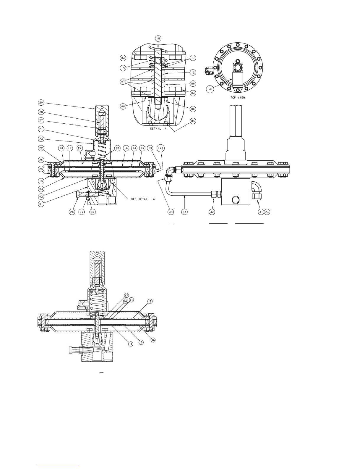
FIGURE 2 - PILOT VALVE
Pilot Pressure < 3.2 psig.
Pilot Pressure > 3.2 psig.
* Spare Parts # Intermediate & High Pressure Pilots ONLY
ITEM NO. DESCRIPTION
01 Pilot body
02 Body gasket *
03 Lower diaphragm case
04 Cap screw
05 Seat o-ring *
06 Spindle assy.
07 Bolt gasket *
08 Seal diaphragm *
09 Boost diaphragm spacer
10 Boost diaphragm *
11 Support plate - Boost
12 Sense diaphragm spacer
13 Diaphragm case spacer
14 Sense diaphragm *
15 Sense pressure ring
16 Support plate - Sense
17 Lower spring guide
18 Spindle stud
19 Nut
20 Range spring
21 Spring button
22 Upper diaphragm case
23 Spring bonnet
24 Exhaust screen
25 Washer - Diaphragm case
26 Cap screw - Diaphragm case
27 Jam nut - Adjusting screw
28 Adjusting screw / Blow down needle
29 Cap - Spring bonnet
30 O-ring - Blow down needle *
31 Exhaust fitting
32 Straight tube fitting
33 Compression elbow
34 Tubing
36 Boost Pressure Ring #
10
IOM-5500
Page 11
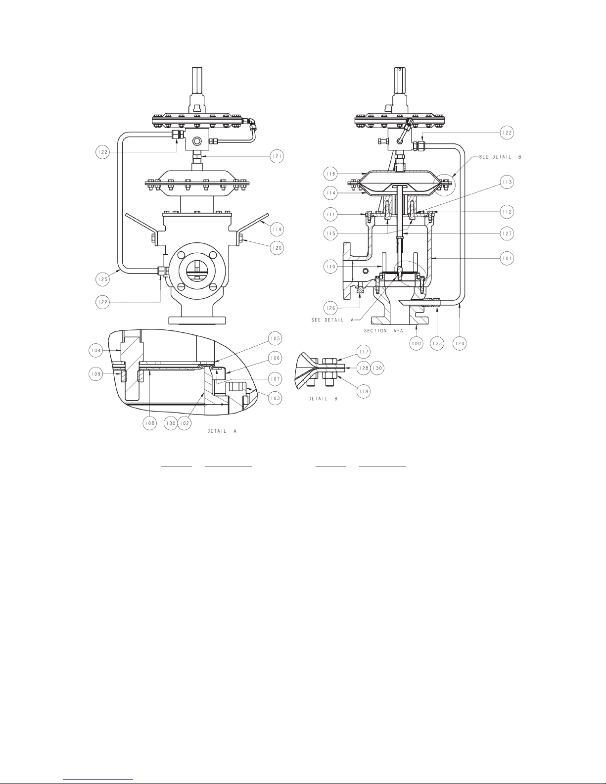
FIGURE 3 - MAIN VALVE
IOM-5500
ITEM NO. DESCRIPTION ITEM NO. DESCRIPTION
100 Spool piece 116 Upper Act. case assy.
101 Pipeaway body 117 Cap screw - Act. case
102 Seat ring 118 Nut - Act case
103 Seat ring bolts 119 Lifting bracket
104 Pallet stem 120 Cap screw - Lifting bracket
105 Stiffener plate 121 Pilot mounting nipple
106 Pallet 122 Sense tube connector 1
107 Diaphragm * 123 Sense tube connector 2
108 Diaphragm retainer 124 Sense tube
109 Lock nut - pallet 125 Discharge tube
110 Pallet guide 126 Plug
111 Cover 127 Support plate
112 Cap screw - Cover 128 Actuator diaphragm *
113 Gasket - Actuator case * 129 Name Plate
114 Lower Act. case assy. 130 Joint tape *
115 Cap screw
* Spare parts
11
Page 12
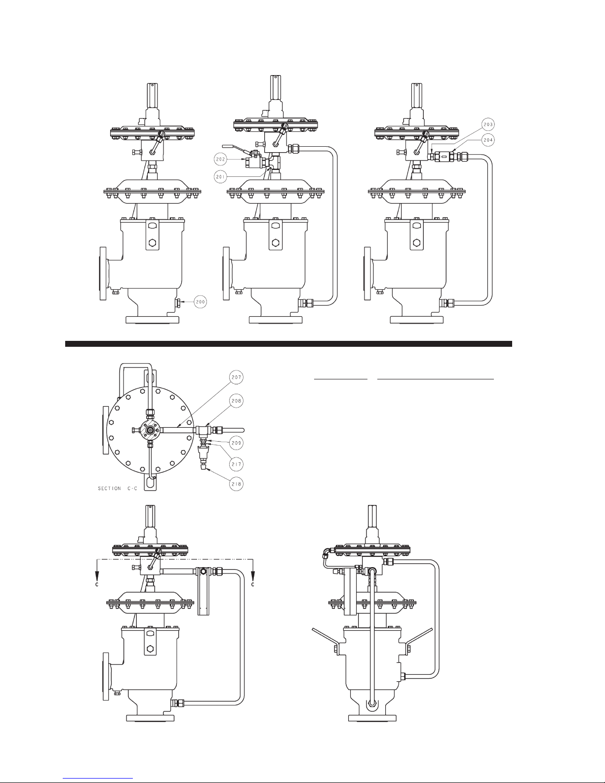
OPTION 2 - Manual Blow DownOPTION 1 - Remote Sense
OPTION 3 - Backflow Preventer
SEE ITEM NO. & DESCRIPTION LIST on page 15.
OPTION 4 - Rotometer to Purge Pilot Sense
12
IOM-5500
Page 13
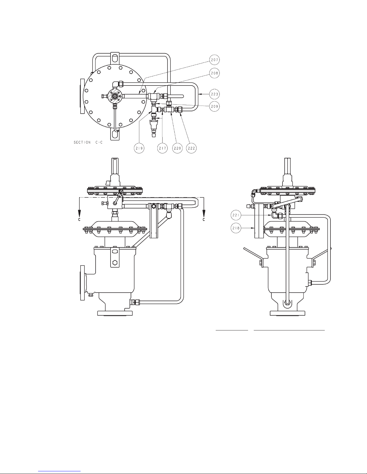
OPTION 5 - Rotometer to Purge Pilot Sense
and Discharge Line
IOM-5500
SEE ITEM NO. & DESCRIPTION LIST on page 15.
13
Page 14
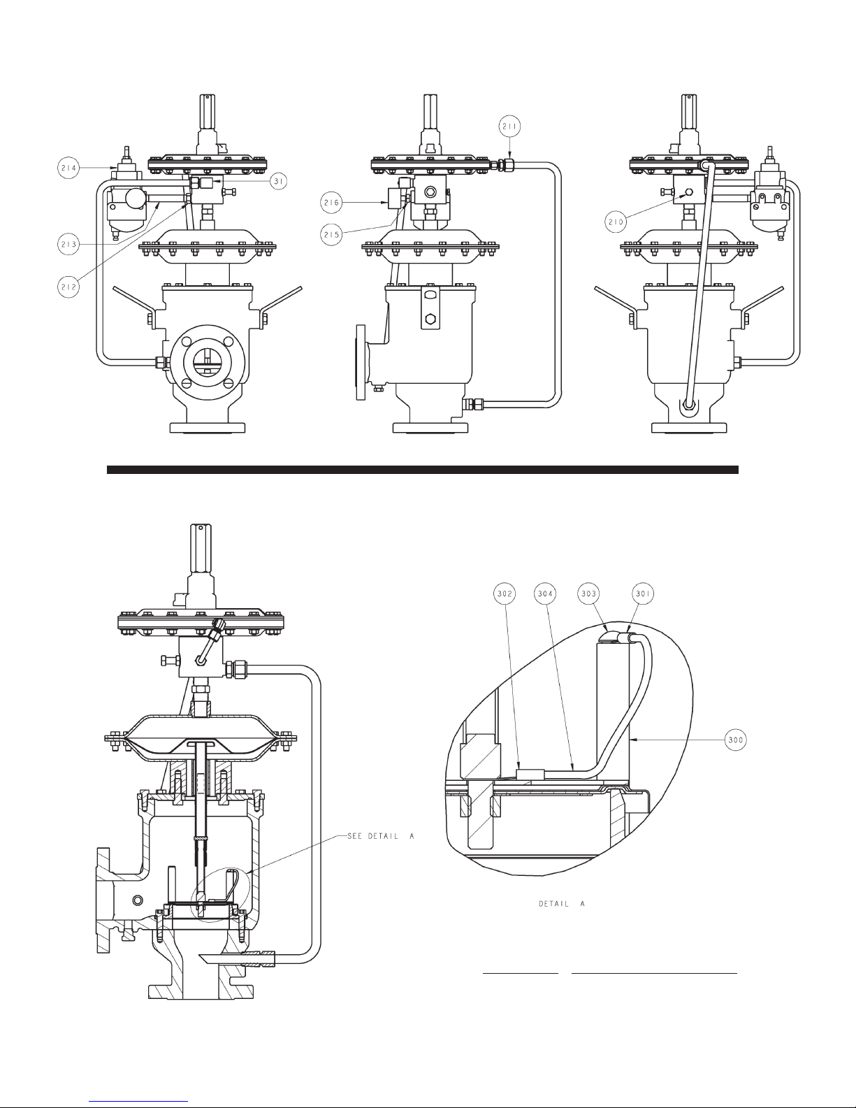
OPTION 6 - Air Assist
OPTION 7 - ATEX
14
SEE ITEM NO. & DESCRIPTION LIST on page 15.
IOM-5500
Page 15
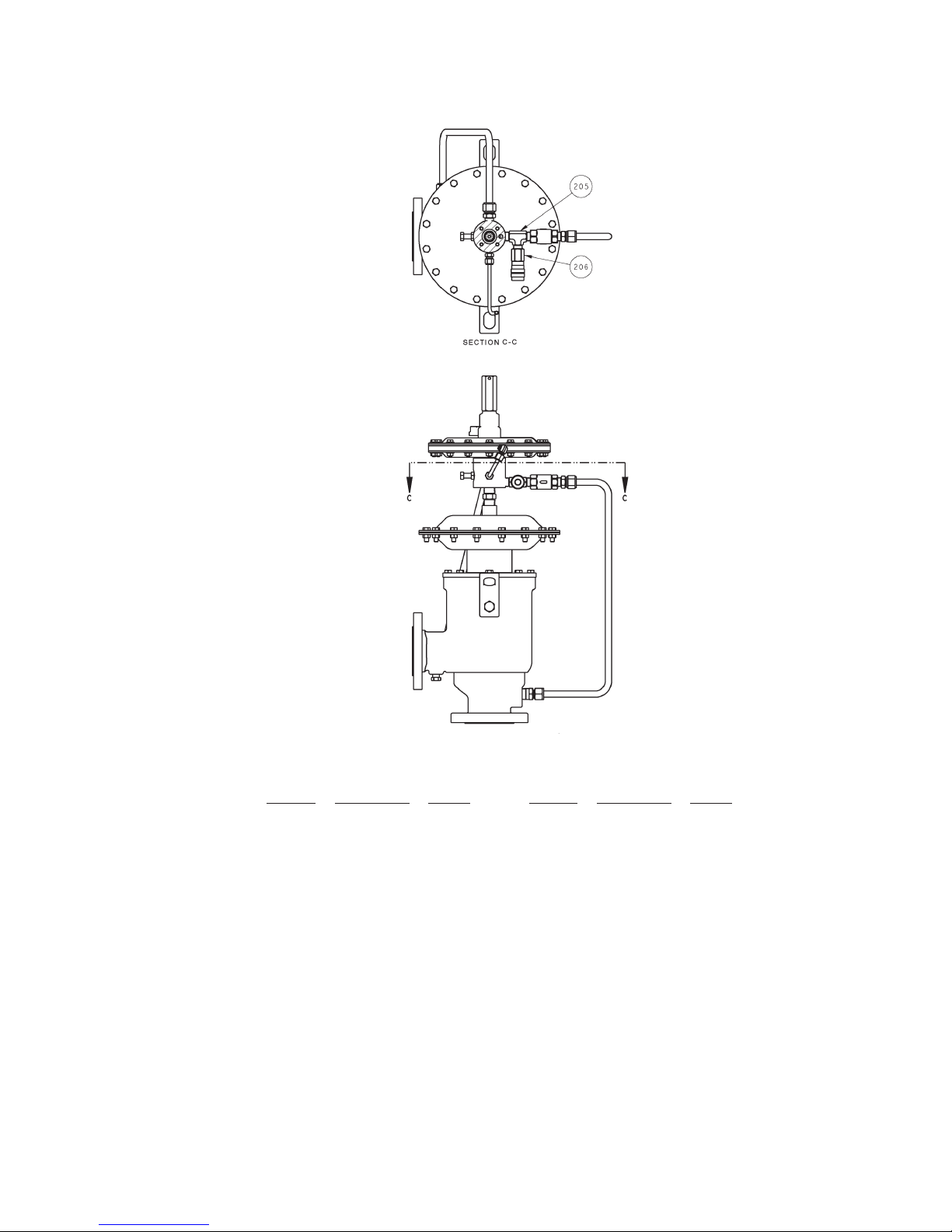
OPTION 8 - Field Test Connection
ITEM NO. DESCRIPTION - OPTION ITEM NO. DESCRIPTION - OPTION
200 Plug - Remote sense 215 Red. bushing Gauge - Air assist
201 MNPT Tee - Manual blowdown 216 Pressure gauge - Air assist
202 Ball valve - Manual blowdown 217 MNPT Flow orifice - Purge
203 Nipple - Check valve 218 Purge meter - Purge
204 Check valve 219 Street Tee - Discharge purge
205 MNPT Tee - Field test conn. 220 Female Tee - Discharge purge
206 Push lock air fitting - Field test 221 Compression elbow - Discharge purge
207 Nipple - Purge 222 Straight tube fitting - Discharge purge
208 Street Tee - Purge 223 Tube - Discharge purge
209 Red. Bushing - Purge 224 Plug
210 Pipe plug - Air assist 300 Pallet guide - ATEX
211 Sense tube conn. - FNPT Air assist 301 Cable eyelet 1 - ATEX
212 Red. bushing - Air assist 302 Cable eyelet 2 - ATEX
213 Nipple - Air assist 303 Screw - ATEX
214 Filter Reg. - Air assist 304 Cable - ATEX
IOM-5500
15
Page 16
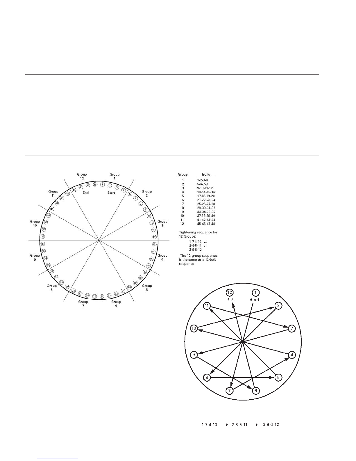
ADDENDUM - A
TIGHTENING SEQUENCE FOR FLANGE BOLTING
GUIDELINES FOR BOLTED FLANGE JOINT ASSEMBLY ACCORDING TO ASME PCC-1 SPECS
STEP LOADING
Install
Round 1
Round 2
Round 3
Hand tighten. Check fl ange gap around circumference for uniformity. If the gap is not reasonably
uniform, make the appropriate adjustments by selective tightening before proceeding.
Tighten to 20% to 30% of target torque. Check fl ange gap around circumference for uniformity.
If the gap is not reasonably uniform, make the appropriate adjustments by selective tightening
before proceeding.
Tighten to 50% to 70% of target torque. Check fl ange gap around circumference for uniformity.
If the gap is not reasonably uniform, make the appropriate adjustments by selective tightening
before proceeding.
Tighten to 100% of target torque. Check fl ange gap around circumference for uniformity. If the gap
is not reasonably uniform, make the appropriate adjustments by selective tightening.
16
IOM-5500
Page 17
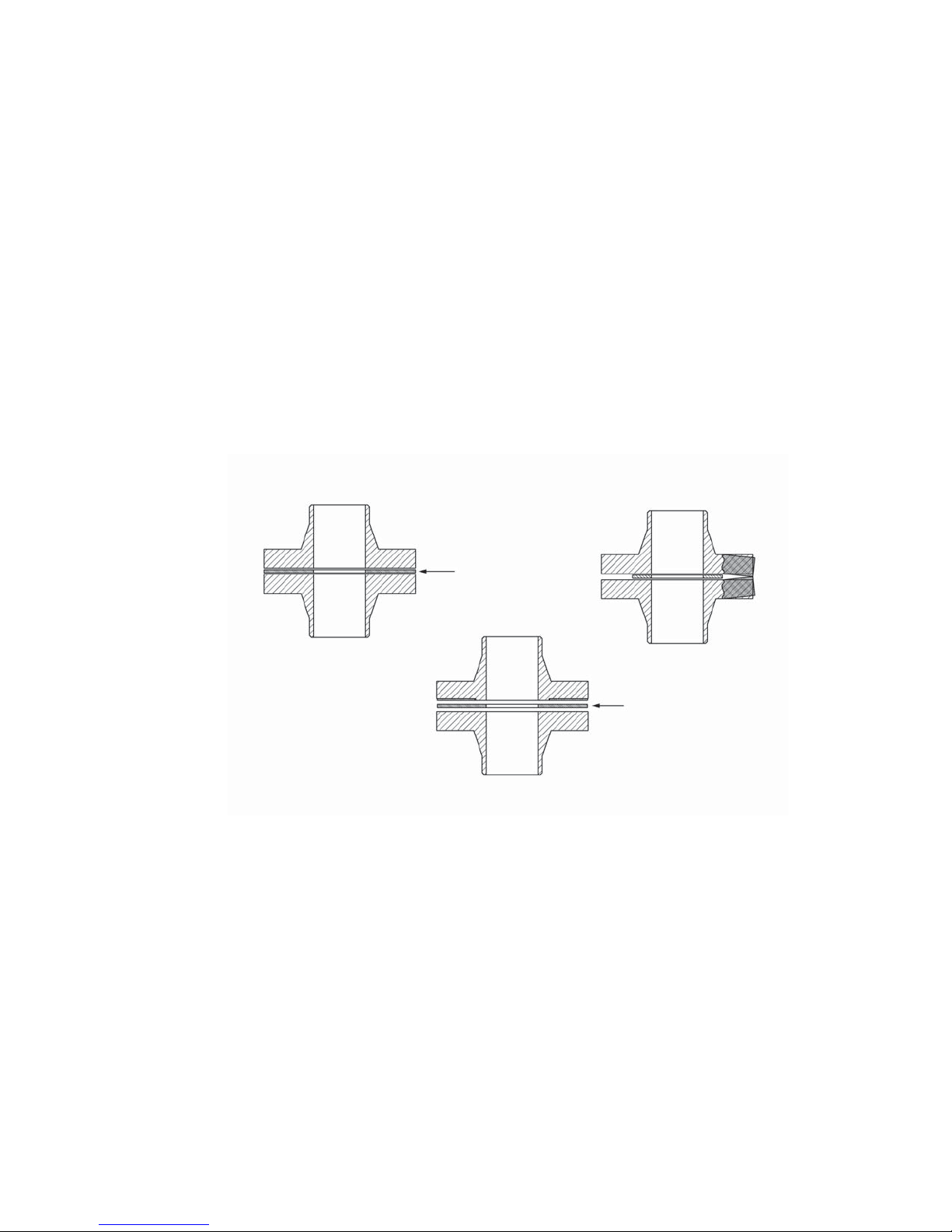
RECOMMENDATIONS FOR PROPER GASKET INSTALLATION
Gasket seating surfaces for tank nozzle flange must be clean, free of scratches,
corrosion, tool marks and flat. Use either a full faced or ring gasket for steel and
stainless steel raised face flanges
FRP and Aluminum vents are furnished with flat faced flanges. It is recommended
that they be installed on mating flat face flanges with a full faced gasket. If the flat
face of the vent is sealing against a raised face steel flange, a spacer or filler ring
must be used to fill the annular space of the raised face steel flange.
Refer to Gasket Dimension Table.
Ensure that the gasket material is suitable for the service. Make sure that the
gasket is compressed evenly and the flanges are not distorted. Utilizing proper
torquing techniques will ensure a tight seal and prevent leakage around the
gasket. See preceding page.
NOTE: Incorrect positioning and/or selection of gasket(s) between the flanges
will cause bending stresses at the flange that may damage the flange joint
as bolting is tightened. This is more likely to occur with aluminum or cast iron
materials.
Correct Installation
Incorrect Installation
Full Faced Gasket
Spacer and
Full Faced Gasket
Correct Installation
IOM-5500
17
Page 18
ATEX 94/9/EC: Explosive Atmospheres and Cashco Inc. Regulators
NOTICE
Only for Product Codes wherein hazard
category ATEX has been selected.
These valves satisfy the safety conditions according to EN 13463-1 and EN 13463-5 for equipment group IIG 2 c.
Caution: Because the actual maximum temperature depends not on the equipment itself, but upon the fluid temperature, a
single temperature class or temperature cannot be marked by the manufacturer.
Specific Precaution to Installer: Electrical grounding of valve must occur to minimize risk of effective electrical discharges.
Specific Precaution to Installer: Atmosphere vent holes should be plugged to further minimize the risk of explosion.
Specific Precaution to Maintenance: The Valve Body/ Housing must be regularly cleaned to prevent buildup of dust deposits.
Specific Precaution to Maintenance: Conduct periodic Continuity Check between Valve Body/ Housing and Tank to minimize
risk of electrical discharges.
Attention: When repairing or altering explosion-protected equipment, national regulations must be adhered to. For maintenance
and repairs involving parts, use only manufacturer's original parts.
ATEX requires that all components and equipment be evaluated. Cashco pressure regulators are considered components.
Based on the ATEX Directive, Cashco considers the location where the pressure regulators are installed to be classified
Equipment-group II, Category 3 because flammable gases would only be present for a short period of time in the event of a leak.
It is possible that the location could be classified Equipment-group II, Category 2 if a leak is likely to occur. Please note that the
system owner, not Cashco, is responsible for determining the classification of a particular installation.
Product Assessment
Cashco performed a conformity assessment and risk analysis of its pressure regulator and control valve models and their
common options, with respect to the Essential Health and Safety Requirements in Annex II of the ATEX directive. The details
of the assessment in terms of the individual Essential Health and Safety Requirements, are listed in Table 1. Table 2 lists all of
the models and options that were evaluated and along with their evaluation.
Models and options not listed in Table 2 should be assumed to not have been evaluated and therefore should not be selected
for use in a potentially explosive environment until they have been evaluated.
Standard default options for each listed model were evaluated even if they were not explicitly listed as a separate option in the
table. Not all options listed in the tables are available to all models listed in the tables. Individual TB’s must be referenced for
actual options.
When specifying a regulator that is to be used in a potentially explosive environment one must review the evaluations in Table 1
and 2 for the specific model and each and every option that is being specified, in order to determine the complete assessment
for the unit.
A summary of the models and options found to have an impact on ATEX assessment due to potential ignition sources or other
concerns from the ATEX Essential Health and Safety Requirements, are listed below.
1. The plastic knob used as standard on some models, (P1, P2, P3, P4, P5, P7, 3381, 4381, 1171, and 2171) is a
potential ignition source due to static electricity. To demonstrate otherwise, the knob must be tested to determine
if a transferred charge is below the acceptable values in IEC 60079-0 Section 26.14 (See items 25, 27, and 28 in
Appendix A). Until the plastic knob has been shown to be acceptable, then either the metal knob option, or a preset
outlet pressure option is required to eliminate this ignition source (See items 45 and 64 in Tables).
2. The pressure gauges offered as options on a few of the regulator models (DA’s, P1-7, D, 764, 521), use a plastic
polycarbonate window that is a potential ignition source due to static electricity. To demonstrate that the gauges are
not a potential source of ignition, the gauges would need to be tested to determine if a transferred charge is below
the acceptable values in IEC 60079-0 Section 26.14 or the pressure gauge supplier must provide documentation
18
IOM-5500
Page 19

indicating the gauge is compliant with the ATEX Directive (See items 26, 27, and 28 in Appendix A). Until compliance
is determined, regulators should not be ordered with pressure gauges for use in potentially explosive environments.
3. Tied diaphragm regulators with outlet ranges greater than 100 psig should be preset to minimize the risk that improper
operation might lead to an outboard leak and a potentially explosive atmosphere (See item 6 in Table 1).
4. Regulators must be ordered with the non-relieving option (instead of the self-relieving option) if the process gas they are
to be used with is hazardous (flammable, toxic, etc.). The self-relieving option vents process gas through the regulator
cap directly into the atmosphere while the non-relieving option does not. Using regulator with the self- relieving option
in a flammable gas system could create an explosive atmosphere in the vicinity of the regulator.
5. Regulators with customer supplied parts are to be assumed to not have been evaluated with regard to ATEX and thus
are not to be used in a potentially explosive environment unless a documented evaluation for the specific customer
supplied parts in question has been made. Refer to Table 1 for all models and options that have been evaluated.
Product Usage
A summary of ATEX related usage issues that were found in the assessment are listed below.
1. Pressure regulators and control valves must be grounded (earthed) to prevent static charge build-up due to the flowing
media. The regulator can be grounded through any mounting holes on the body with metal to metal contact or the
system piping can be grounded and electrical continuity verified through the body metal seal connections. Grounding
of the regulator should follow the same requirements for the piping system. Also see item 30 in Table 1.
2. The system designer and users must take precautions to prevent rapid system pressurization which may raise surface
temperatures of system components and tubing due to adiabatic compression of the system gas.
3. Heating systems installed by the user could possibly increase the surface temperature and must be evaluated by the
user for compliance with the ATEX Directive. User installation of heating systems applied to the regulator body or
system piping that affects the surface temperature of the pressure regulator is outside the scope of this declaration and
is the responsibility of the user.
4. The Joule-Thomson effect may cause process gases to rise in temperature as they expand going through a regulator.
This could raise the external surface temperature of the regulator body and downstream piping creating a potential
source of ignition. Whether the Joule-Thomson effect leads to heating or cooling of the process gas depends on
the process gas and the inlet and outlet pressures. The system designer is responsible for determining whether the
process gas temperature may rise under any operating conditions. If a process gas temperature rise is possible under
operating conditions, then the system designer must investigate whether the regulator body and downstream piping
may increase in temperature enough to create a potential source of ignition.
The process gas expansion is typically modeled as a constant enthalpy throttling process for determining the temperature change.
A Mollier diagram (Pressure – Enthalpy diagram with constant temperature, density, & entropy contours) or a Temperature –
Entropy diagram with constant enthalpy lines, for the process gas, can be used to determine the temperature change. Helium
and hydrogen are two gases that typically increase in temperature when expanding across a regulator. Other gases may
increase in temperature at sufficiently high pressures.
Product Declaration
If the above issues are addressed by selecting options that do not have potential sources of ignition, avoiding options that
have not been assessed, and by taking the proper usage issue precautions, then Cashco regulators can be considered to be a
mechanical device that does not have its own source of ignition and thus falls outside the scope of the ATEX directive.
Cashco, Inc.
P.O. Box 6
Ellsworth, KS 67439-0006
PH (785) 472-4461
Fax. # (785) 472-3539
www.cashco.com
email: [email protected]
Printed in U.S.A. 5500-IOM
IOM-5500
Cashco GmbH
Handwerkerstrasse 15
15366 Hoppegarten, Germany
PH +49 3342 30968 0
Fax. No. +49 3342 30968 29
www.cashco.com
email: [email protected]
Cashco do Brasil, Ltda.
Al.Venus, 340
Indaiatuba - Sao Paulo, Brazil
PH +55 11 99677 7177
Fax. No.
www.cashco.com
email: [email protected]
19
 Loading...