

Page 1

INSTALLATION, OPERATION AND MAINTENANCE MANUAL (IOM)
Model 1049
Secure-Gard Pilot Operated Vent Valve
ISO Registered Company
SECTION I
I. DESCRIPTION AND SCOPE
The Model 1049 Secure-Gard is a pilot operated vent
valve intended for installation on atmospheric and low
pressure storage tanks, vapor recovery systems, and
process systems.
SECTION II
IOM - 1049
01-17
WARNING
The Model 1049 is a low pressure pilot operated valve.
In as such, does not supply vacuum relief. If vacuum
relief is required, it should be provided by a separate
device.
CAUTION
Follow your company’s safety procedures to avoid
injury to personnel or damage to equipment.
II. PRIOR TO INSTALLATION
Remove all packing material inside and outside of the valve prior to installation.
SAFETY WARNING: In addition to your company’s safety procedures, this section includes guidelines that should
be followed during the installation, operation, and maintenance of Valve Concepts, Inc’s Pilot Operated Vent Valve.
It is necessary to completely read and understand these guidelines.
Tank or system over pressure protection is the primary function of pilot operated vent valves. It must be selected to
meet the total pressure flow requirements within the Maximum Allowable Working Pressure of the system on which
it is installed. Consult API Standard 2000 for tank protection sizing procedures. Improperly specified vent valves
may result in structural damage to the tank or system, and may cause severe personal injury or death.
Valves are pre-set at the factory per customer purchase specifications. DO NOT change the set pressure without
consulting the factory or your local VCI representative. Improper adjustment may cause the valve to malfunction.
DO NOT attempt to remove the valve from the tank or process vessel without first bleeding all pressure from the
system. ALTERNATIVE MEANS OF PRESSURE VENTING MUST BE PROVIDED WHEN THE VALVE IS OUT
OF SERVICE.
The valve has been exposed to process while in service. Observe all plant procedures and Material Safety Data
Sheets (MSDS) for the products in the system while inspecting, adjusting, or servicing the valve. Take appropriate
safety precautions regarding eye protection, respiration and skin contact.
SECTION III
III. INSTALLATION
The inlet and outlet flanges are normally standard ANSI 150 lbs. class flanges unless otherwise indicated and
should be connected following accepted piping practices.
Page 2

The inlet is vertical and the outlet is horizontal. The
valve should be installed in the normal upright position
with the cap at the top of the valve and the valve inlet at
the bottom. The outlet is to the side.
but not to exceed the maximum pressure rating of the
rotameter. (Standard rotameter supplied by Valve
Concepts is rated to 250 psig.) Once the gas source is
connected, the purge flow can be adjusted by turning
the knob at the top of the rotameter and observing the
For valves using the remote sensing port connection,
sense lines should be a 1/2” O.D. tube or larger and the
flow indicator. The purge mechanism is designed not
to affect the set pressure of the vent valve.
length should not exceed fifteen feet. Longer lengths
may be used with larger diameter sense lines. The
sense line should slope downward from the sense port
to the tank to allow condensate, if any, to drain back
into the tank and not block the sensing capability.
When the tank pressure is below set pressure, the main
valve seat will be closed. If the rotameter is mounted
to purge both the pilot sense and discharge lines, there
will be a very small flow to the valve outlet from the
purge mechanism.
VALVES WITH PURGE ROTAMETER
VALVE WITH AIR OR N2 ASSIST:
For valves with a rotameter mounted for purging either
the pilot sense line only or both pilot sense and discharge lines, connect the purge gas source, usually dry
nitrogen, to the 1/4” FNPT connection at the bottom of
the rotameter. The pressure of the purge gas source
must be higher than the set pressure of the vent valve,
For valves with air or nitrogen assist pilot, connect the
gas source to the 1/4” FNPT connection at the inlet of
the filter regulator. The pressure must be a minimum of
5 psig, but not to exceed the maximum pressure rating
of the filter regulator. (The standard filter regulator sup-
plied by Valve Concepts is rated at 300 psig.)
INSTALLATION DIAGRAMS FOR STANDARD ACCESSORIES & CONFIGURATIONS
Standard Confi guration
Internal Sensing, SS Pilot Filter Element and
Pilot Exhaust to Atmosphere
Option 1
With Pilot Exhaust Tubed to Main Valve Outlet
With Manual Blowdown Valve
Option 2
With Remote Sensing
Option 3
2 IOM-1049
Page 3

INSTALLATION DIAGRAMS FOR STANDARD ACCESSORIES & CONFIGURATIONS
Option 4
With Back Flow Preventer to Prevent Back Flow
through Main Valve and Pilot
Option 5
With Field Test Connection
(Back Flow Preventer Included)
Option 7
With Rotameter to Purge Pilot Sense
and Discharge Lines
Option 8
With Field Test Connection, Back Flow Preventer and
Rotameter to Purge Pilot Sense and Discharge Lines
Option 6
With Rotameter to Purge Pilot Sense
Option A
Internal Sensing, SS Pilot Filter Element, Pilot Exhaust
to Main Valve Outlet with Manual Blowdown Valve
3IOM-1049
Page 4

SECTION IV
IV. START-UP
Operation of the Model 1049 is automatic once the set
pressure has been set. (The set pressure is bench-set
per the customer’s specifi ed setting at the factory prior
to shipment.) NOTE: The set pressure is defi ned as
the pressure at which the valve should start to open on
increasing tank pressure.
For the valve to be in the closed position, tank pressure
must reach the actuator though the pilot.
Upon initial start-up, the valve may be opened for a
few seconds, but will close when the pressure in the
actuator chamber reaches tank pressure.
To adjust the set pressure, remove the hex cap at the
top of the valve and loosen the jam nut around the
adjusting screw. Clockwise rotation of the adjusting
screw will increase the set pressure. Counter clockwise
rotation will decrease the set pressure. Do not adjust
the set pressure beyond the nameplate range. Tighten
the jam nut after adjustments are made and replace
the hex cap.
For valves with air or nitrogen assist pilot, the gas
source must be connected to the fi lter regulator before
the valve will be in the closed position. (The fi lter
regulator is pre-set at the factory to 5 psig, and the
CA-1 back pressure regulator is pre-set at the factory
to 10 psig.)
SECTION V
V. MAINTENANCE
It is strongly recommended that if the valve needs to
be serviced, that it be sent to the factory or a factory
authorized repair facility. Trained mechanics with
specialized test equipment will ensure that the valve is
accurately set.
The Model 1049 should be periodically checked to
ensure proper operation. The frequency required
depends on the severity of the service conditions. At
least once a year is recommended.
Maintenance procedures hereinafter are based upon
removal of the unit from the vessel where installed.
To disassemble the valve, refer to the appropriate
drawings.
To replace soft goods of the pilot valve:
The pilot assembly may be removed by unscrewing the
nipple (131) from the upper case weldment (201).
WARNING
SPRING UNDER COMPRESSION. Prior to
re mov ing diaphragm case bolts, relieve spring
com pres sion by backing out the adjusting screw.
Failure to do so may result in flying parts that
could cause personal injury.
To disassemble the diaphragm case, relax the
compressed spring by fi rst unscrewing the cap
(105), then loosen the jam nut (114) and back off the
adjusting screw (113). The ring of nuts, lockwashers,
4 IOM-1049
washers, and bolts (109, 110, 121 and 120) around the
periphery can now be removed. Remove the bolts and
lockwashers (120 and 110), holding the spring bonnet
(104) and upper diaphragm case (102) together.
Replace the round gasket (122) and reassemble items
102, 104, 110 and 120.
Remove the set pressure spring (115), spring button
(112), and ring gasket (134) and set to the side. Hold
the wrenching washers (128) with a wrench, and
loosen and remove nut (109). Remove lockwashers
(110), lower spring guide washers (111), wrenching
washers (128), support plates (106), diaphragm (107),
bolt gaskets (126), and spacer (127) and set to the
side. Remove lock washers (110) and bolts (120) from
the pilot body (101) and lower diaphragm case (103).
Remove the seal diaphragm (124), the body gasket
(125) and the spindle assembly (108). Take the o-ring
seat (133) and the bolt gasket (126) off the spindle
assembly (108) and replace with new parts.
Reinstall the spindle assembly (108) with o-ring (133)
and bolt gasket (126). Set new seal diaphragm (124)
over the stem of the spindle assembly and the body
gasket (125) on top of the seal diaphragm (124). Then,
reinstall the lower diaphragm case (103) to the pilot
body (101) with lock washers (110) and bolts (120).
Slide the spacer (127) over the stem of the spindle
assembly and place another new bolt gasket (126) on
top of the spacer. Place the fi rst support plate (106)
on the stem, then the new diaphragm (107), then the
other bolt gasket (126), then the fi nal support plate
(106). Place the wrenching washers (128), lower
Page 5
spring guide washers (111), and lockwashers (110) on
the stem. While holding the wrenching washers (128)
with a wrench, (and making sure the bolt holes of the
diaphragm and diaphragm case align) thread the nuts
(109) and tighten. Place the set pressure spring (115)
and the spring button (112) on the spindle assembly
(108). Place a new ring gasket (134) on top of the
diaphragm (107). Place the upper diaphragm case
(102) on top of the lower diaphragm case (103). Install
the washers (121), bolts (120), lockwashers (110), and
nuts (109) and tighten.
Thread the blowdown needle (117) completely in, then
back out 3 full turns, and lock the jam nut (114).
To replace soft goods of the main valve actuator:
Remove the washers (208), bolts (205), lockwashers
(206), and nuts (207). Lift pilot assembly off and set
to the side. Replace the actuator diaphragm (203).
Reassemble in reverse order.
To replace soft goods of the main valve:
Remove the nipple (131) from the pilot body (101).
Loosen the jam nut (114). With needle nose pliers
remove the c-ring (119) and unthread the blowdown
needle (117). Remove the TFE o-ring (118). Place a
new TFE o-ring (118) on the blowdown needle (117).
Reinstall in reverse order.
CAUTION
DO NOT overtighten threaded connections since
damage or breakage may result. Wrap all NPT threads
with TFE tape. Apply anti-seize compound on bolt
threads. Very lightly lubricate all o-rings with a
lubricant that is compatible with the service, sealing
surfaces of gaskets and diaphragms also.
Remove the bolts (311) and the lockwashers (310)
holding the cover/lower case weldment (202) to the
main body. Carefully remove the lower case weldment
(202) and the cover gasket (307). Remove the seat
plate assembly (303) and the o-ring seat (305).
Remove the bolts (308) and the lockwashers (309)
holding the nozzle (304) to the body (301). Remove
the nozzle (304). Replace the nozzle gasket (306).
Reinstall the o-ring seat (305) into the nozzle (304).
Be sure the o-ring is completely in the nozzle, and that
the exposed surface is flat. Bolt nozzle (304) back into
the body (301) with bolts (308) and lockwashers (309)
and tighten. Install the seat plate assembly (303).
Install a new cover gasket (307) and reinstall the cover/
lower case weldment (202) with the bolts (310) and the
lockwashers (311).
5IOM-1049
Page 6
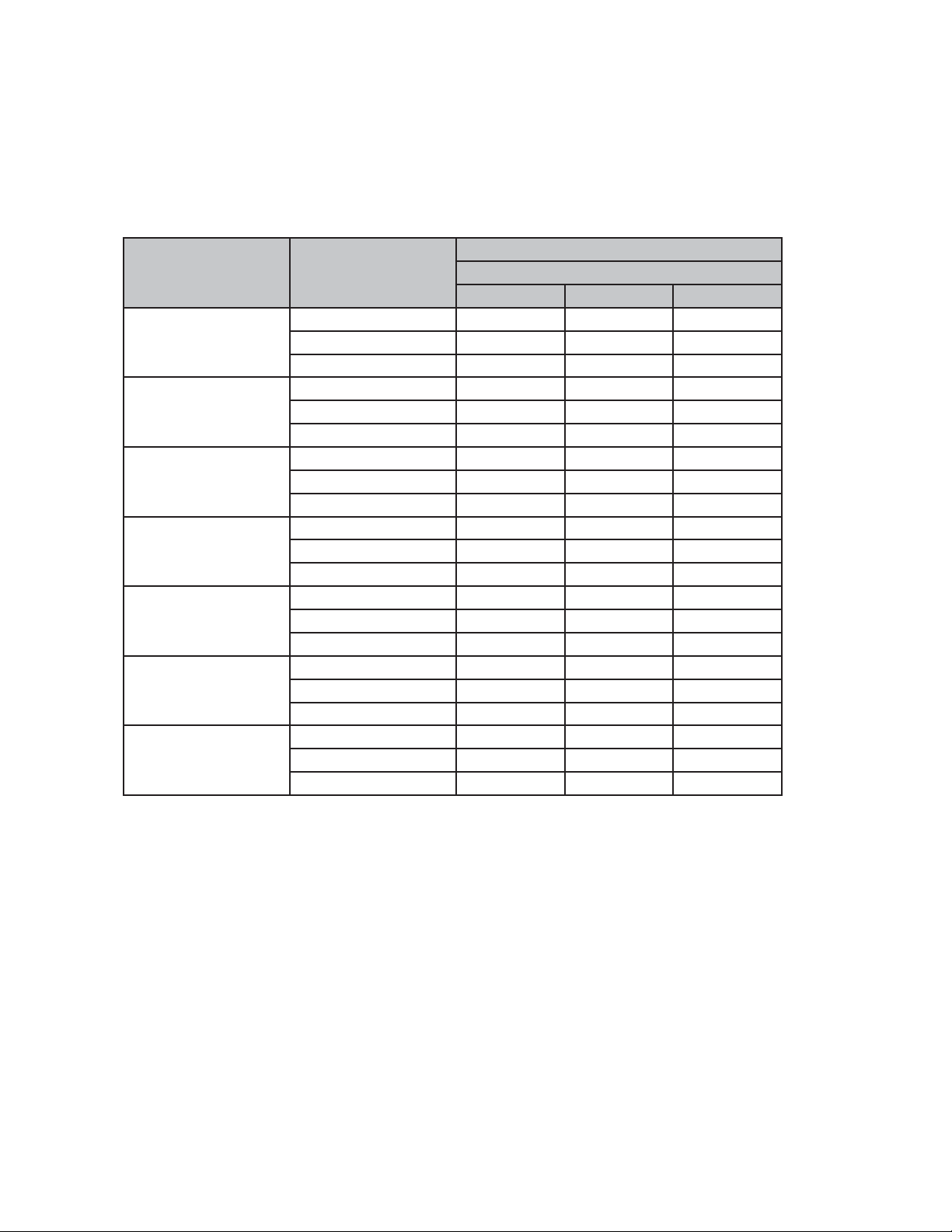
TABLE 1
Soft Goods Kit Part Numbers
Soft goods kits, consisting of all the non-metallic components (o-rings, sense diaphragm, gaskets, etc) are available.
The drawings indicate which components are included in the kit. For other replacement parts, specify by item
number and description plus material, if the part number is not known.
Always provide the model number, size if applicable, and the serial number when ordering kits/replacement parts.
Soft Good Kit Numbers
Line Size Spring Range
4” - 1.5 psig 31452033 31452055 31452044
2” x 3”
3” x 4”
4” x 6”
6” x 8”
8” x 10”
10” x 12”
12” x 16”
1.5 - 3 psig 31452933 31452955 31452944
3.2 -14 psig 31452133 31452155 31452144
4” - 1.5 psig 31453033 31453055 31453044
1.5 - 3 psig 31453933 31453955 31453944
3.2 -14 psig 31453133 31453155 31453144
4” - 1.5 psig 31454033 31454055 31454044
1.5 - 3 psig 31454933 31454955 31454944
3.2 -14 psig 31454133 31454155 31454144
4” - 1.5 psig 31456033 31456055 31456044
1.5 - 3 psig 31456933 31456955 31456944
3.2 -14 psig 31456133 31456155 31456144
4” - 1.5 psig 31458033 31458055 31458044
1.5 - 3 psig 31458933 31458955 31458944
3.2 -14 psig 31458133 31458155 31458144
4” - 1.5 psig 31451033 31451055 31451044
1.5 - 3 psig 31451933 31451955 31451944
3.2 -14 psig 31451133 31451155 31451144
4” - 1.5 psig 31459033 31459055 31459044
1.5 - 3 psig 31459933 31459955 31459944
3.2 -14 psig 31459133 31459155 31459144
Buna-N EPDM Viton
O-RING MATERIAL
6 IOM-1049
Page 7

SECTION VI
VII. TROUBLE SHOOTING GUIDE
1. Model 1049 opens below set point.
Possible Cause Remedy
A. Sense line is clogged. A1. Check sense line and sense port for blockage. Clean as
needed
B. Incorrect set pressure. B1. Adjust set pressure screw to proper set pressure.
C. Pilot or actuator diaphragm failure. C1. Disassemble and check diaphragms. Replace if required.
D. Loss of external air/N2 source for air/N2 assist pilot. D1. Check external source.
2. Model 1049 will not open.
Possible Cause Remedy
A. Incorrect set pressure. A1. Adjusting set pressure screw to proper set pressure.
B. Pilot exhaust plugged. B1. Check pilot exhaust for blockage. Clean as needed.
C. Sense line clogged. C1. Check sense line and sense port for blockage. Clean as
needed.
3. Vapor leaking from pilot spring bonnet.
Possible Cause Remedy
A. Pilot diaphragm failure. A1. Disassemble and check pilot diaphragm. Replace if re-
quired.
4. Seat Leakage
Possible Cause Remedy
A. O-ring seat has failed. A1. Disassemble and check o-ring seat. Replace if required.
B. Foreign particles trapped between seat and seat
plate.
C. Sense line clogged. C1. Check sense line and sense port for blockage. Clean
D. Back pressure higher than tank pressure. D1. Vent operating properly.
B1. Check and clean as needed.
as needed
7IOM-1049
Page 8
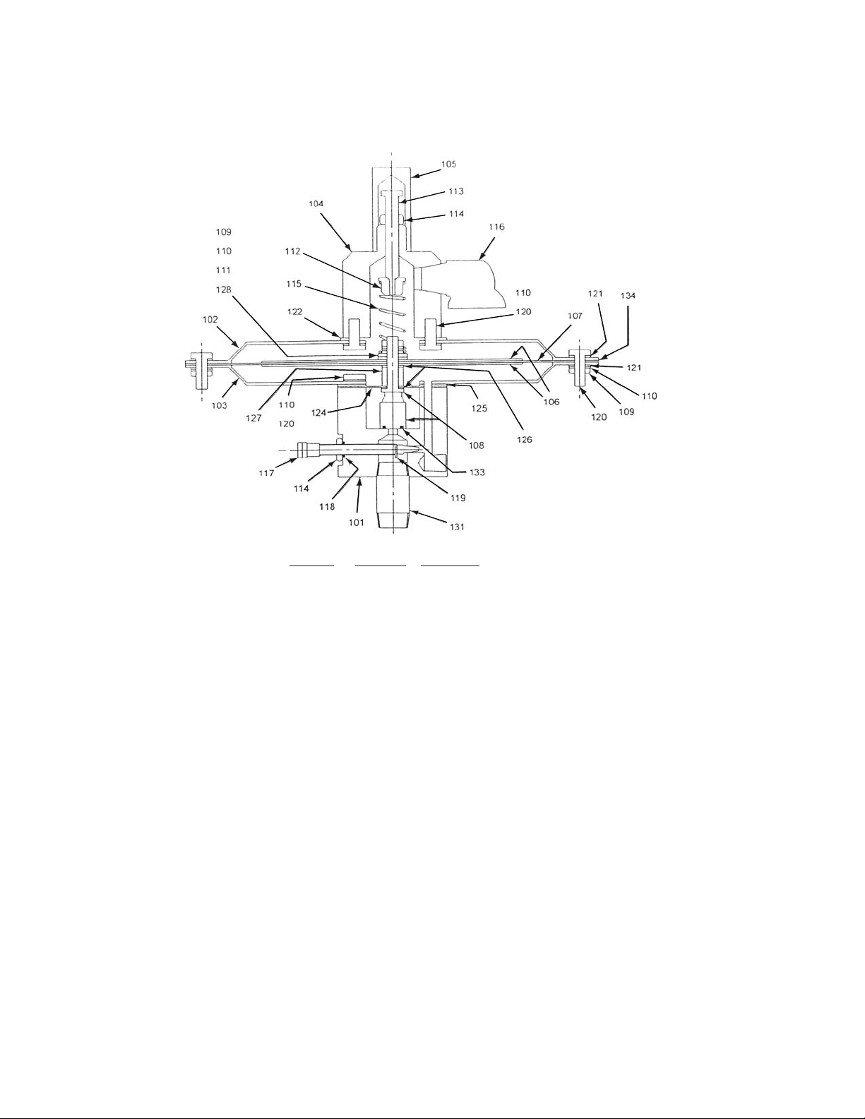
Model 1049 Pilot Assembly
ITEM NO. QUANTITY PART NAME
101 1 Pilot Body
102 1 Upper Diaphragm Case
103 1 Lower Diaphragm Case
104 1 Spring Bonnet
105 1 Cap
106 2 Support Plate
107‡ 1 Diaphragm
108 1 Spindle Assembly
109 17 Nut
110 20 Lockwasher
111 2 Lower Spring Guide Washer
112 1 Spring Button
113 1 Adjusting Screw
114 2 Jam Nut
115 1 Set Pressure Spring
116 1 Bug Screen Vent
117 1 Blowdown Needle
118‡ 1 O-Ring - TFE
119 1 C-Ring
120 20 Bolt
121 16 Washer
122‡ 1 Round Gasket
124‡ 1 Seal Diaphragm
125‡ 1 Body Gasket
126‡ 3 Bolt Gasket
127 1 Spacer
128 2 Wrenching Washer
131 1 Nipple
133‡ 1 O-Ring Seat
134‡ 1 Ring Gasket
‡Parts are included in the Soft Goods Kit
8 IOM-1049
Page 9
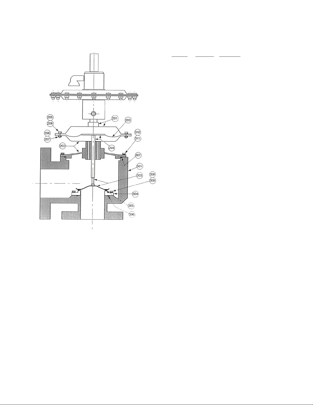
Model 1049 Main Valve Body & Actuator
ITEM NO. QUANTITY PART NAME
201 1 Upper Case Weldment
202 1 Cover/Lower Case Weldment
203 ‡ 1 Actuator Diaphragm
204 1 Support Plate Weldment
205 16 Bolt
206 16 Lockwasher
207 16 Nut
208 16 Washer
301 1 Body
303 1 Seat Plate Assembly
304 1 Nozzle
305 ‡ 1 O-Ring Seat
306 ‡ 1 Nozzle Gasket
307 ‡ 1 Cover Gasket
308 6 Bolts
309 6 Lockwashers
For 2” x 3” Size Only
310 6 Bolts
311 6 Lockwashers
For 3” x 4” Size Only
310 8 Bolts
311 8 Lockwashers
For 4” x 6” Size Only
310 8 Bolts
311 8 Lockwashers
For 6” x 8” Size Only
310 8 Bolts
311 8 Lockwashers
For 8” x 10” Size Only
310 12 Bolts
311 12 Lockwashers
For 10” x 12” Size Only
310 16 Bolts
311 16 Lockwashers
For 12” x 16” Size Only
310 16 Bolts
311 16 Lockwashers
‡Parts are included in the Soft Goods Kit
Valve Concepts, Inc.
3644 Westchase Drive
Houston, TX 77042-5224
PH (713) 271-7171
Fax. # (713) 271-0153
www.valveconcepts.com
email: [email protected]
Printed in U.S.A. Model 1049 IOM
9IOM-1049
Page 10
ATEX 94/9/EC: Explosive Atmospheres and Cashco Inc. Regulators
NOTICE
Only for Product Codes wherein hazard
category ATEX has been selected.
These valves satisfy the safety conditions according to EN 13463-1 and EN 13463-5 for equipment group IIG 2 c.
Caution: Because the actual maximum temperature depends not on the equipment itself, but upon the fluid temperature, a
single temperature class or temperature cannot be marked by the manufacturer.
Specific Precaution to Installer: Electrical grounding of valve must occur to minimize risk of effective electrical discharges.
Specific Precaution to Installer: Atmosphere vent holes should be plugged to further minimize the risk of explosion.
Specific Precaution to Maintenance: The Valve Body/ Housing must be regularly cleaned to prevent buildup of dust deposits.
Specific Precaution to Maintenance: Conduct periodic Continuity Check between Valve Body/ Housing and Tank to minimize
risk of electrical discharges.
Attention: When repairing or altering explosion-protected equipment, national regulations must be adhered to. For maintenance
and repairs involving parts, use only manufacturer's original parts.
ATEX requires that all components and equipment be evaluated. Cashco pressure regulators are considered components.
Based on the ATEX Directive, Cashco considers the location where the pressure regulators are installed to be classified
Equipment-group II, Category 3 because flammable gases would only be present for a short period of time in the event of a leak.
It is possible that the location could be classified Equipment-group II, Category 2 if a leak is likely to occur. Please note that the
system owner, not Cashco, is responsible for determining the classification of a particular installation.
Product Assessment
Cashco performed a conformity assessment and risk analysis of its pressure regulator and control valve models and their
common options, with respect to the Essential Health and Safety Requirements in Annex II of the ATEX directive. The details
of the assessment in terms of the individual Essential Health and Safety Requirements, are listed in Table 1. Table 2 lists all of
the models and options that were evaluated and along with their evaluation.
Models and options not listed in Table 2 should be assumed to not have been evaluated and therefore should not be selected
for use in a potentially explosive environment until they have been evaluated.
Standard default options for each listed model were evaluated even if they were not explicitly listed as a separate option in the
table. Not all options listed in the tables are available to all models listed in the tables. Individual TB’s must be referenced for
actual options.
When specifying a regulator that is to be used in a potentially explosive environment one must review the evaluations in Table 1
and 2 for the specific model and each and every option that is being specified, in order to determine the complete assessment
for the unit.
A summary of the models and options found to have an impact on ATEX assessment due to potential ignition sources or other
concerns from the ATEX Essential Health and Safety Requirements, are listed below.
1. The plastic knob used as standard on some models, (P1, P2, P3, P4, P5, P7, 3381, 4381, 1171, and 2171) is a
potential ignition source due to static electricity. To demonstrate otherwise, the knob must be tested to determine
if a transferred charge is below the acceptable values in IEC 60079-0 Section 26.14 (See items 25, 27, and 28 in
Appendix A). Until the plastic knob has been shown to be acceptable, then either the metal knob option, or a preset
outlet pressure option is required to eliminate this ignition source (See items 45 and 64 in Tables).
2. The pressure gauges offered as options on a few of the regulator models (DA’s, P1-7, D, 764, 521), use a plastic
polycarbonate window that is a potential ignition source due to static electricity. To demonstrate that the gauges are
not a potential source of ignition, the gauges would need to be tested to determine if a transferred charge is below
Page 11

indicating the gauge is compliant with the ATEX Directive (See items 26, 27, and 28 in Appendix A). Until compliance
is determined, regulators should not be ordered with pressure gauges for use in potentially explosive environments.
3. Tied diaphragm regulators with outlet ranges greater than 100 psig should be preset to minimize the risk that improper
operation might lead to an outboard leak and a potentially explosive atmosphere (See item 6 in Table 1).
4. Regulators must be ordered with the non-relieving option (instead of the self-relieving option) if the process gas they are
to be used with is hazardous (flammable, toxic, etc.). The self-relieving option vents process gas through the regulator
cap directly into the atmosphere while the non-relieving option does not. Using regulator with the self- relieving option
in a flammable gas system could create an explosive atmosphere in the vicinity of the regulator.
5. Regulators with customer supplied parts are to be assumed to not have been evaluated with regard to ATEX and thus
are not to be used in a potentially explosive environment unless a documented evaluation for the specific customer
supplied parts in question has been made. Refer to Table 1 for all models and options that have been evaluated.
Product Usage
A summary of ATEX related usage issues that were found in the assessment are listed below.
1. Pressure regulators and control valves must be grounded (earthed) to prevent static charge build-up due to the flowing
media. The regulator can be grounded through any mounting holes on the body with metal to metal contact or the
system piping can be grounded and electrical continuity verified through the body metal seal connections. Grounding
of the regulator should follow the same requirements for the piping system. Also see item 30 in Table 1.
2. The system designer and users must take precautions to prevent rapid system pressurization which may raise surface
temperatures of system components and tubing due to adiabatic compression of the system gas.
3. Heating systems installed by the user could possibly increase the surface temperature and must be evaluated by the
user for compliance with the ATEX Directive. User installation of heating systems applied to the regulator body or
system piping that affects the surface temperature of the pressure regulator is outside the scope of this declaration and
is the responsibility of the user.
4. The Joule-Thomson effect may cause process gases to rise in temperature as they expand going through a regulator.
This could raise the external surface temperature of the regulator body and downstream piping creating a potential
source of ignition. Whether the Joule-Thomson effect leads to heating or cooling of the process gas depends on
the process gas and the inlet and outlet pressures. The system designer is responsible for determining whether the
process gas temperature may rise under any operating conditions. If a process gas temperature rise is possible under
operating conditions, then the system designer must investigate whether the regulator body and downstream piping
may increase in temperature enough to create a potential source of ignition.
The process gas expansion is typically modeled as a constant enthalpy throttling process for determining the temperature change.
A Mollier diagram (Pressure – Enthalpy diagram with constant temperature, density, & entropy contours) or a Temperature –
Entropy diagram with constant enthalpy lines, for the process gas, can be used to determine the temperature change. Helium
and hydrogen are two gases that typically increase in temperature when expanding across a regulator. Other gases may
increase in temperature at sufficiently high pressures.
Product Declaration
If the above issues are addressed by selecting options that do not have potential sources of ignition, avoiding options that
have not been assessed, and by taking the proper usage issue precautions, then Cashco regulators can be considered to be a
mechanical device that does not have its own source of ignition and thus falls outside the scope of the ATEX directive.
The contents of this publication are presented for informational purposes only, and while every effort has been made to ensure their accuracy, they are not to be
construed as warranties or guarantees, express or implied, regarding the products or services described herein or their use or applicability. We reserve the right to
modify or improve the designs or specifications of such product at any time without notice.
Cashco, Inc. does not assume responsibility for the selection, use or maintenance of any product. Responsibility for proper selection, use and maintenance of any
Cashco, Inc. product remains solely with the purchaser.
 Loading...