


SAFETY INSTRUCTION ......................................................................................................................... 1
Chapter 1 Product Overview ................................................................................................................ 1
1.1 Rear Panel ..................................................................................................................................... 1
1.2 Remote Controller (For Reference Only)....................................................................................... 2
Chapter 2 DVR Installation & Connection ........................................................................................... 3
2.1 HDD Installation ............................................................................................................................. 3
2.2 Connection Diagram ...................................................................................................................... 4
2.3 Power Supply Connection ............................................................................................................. 4
Chapter 3 DVR Common Operations ................................................................................................... 5
3.1 Using the Supplied Mouse ............................................................................................................. 5
3.2 Using the Virtual Keyboard ............................................................................................................ 5
3.3 Password ....................................................................................................................................... 6
Chapter 4 DVR Starting up ................................................................................................................... 7
4.1 Start Wizard ................................................................................................................................... 7
4.1.1 Start Wizard ............................................................................................................................ 7
4.1.2 Network Configuration ............................................................................................................ 7
4.1.3 Date/Time ................................................................................................................................ 9
4.1.4 IP Camera ............................................................................................................................. 10
4.1.5 Disk ....................................................................................................................................... 12
4.1.6 Resolution ............................................................................................................................. 12
4.1.7 Mobile ................................................................................................................................... 13
4.1.8 Summary ............................................................................................................................... 13
4.2 Live View Screen Overview ......................................................................................................... 14
4.2.1 Camera Quick Toolbar .......................................................................................................... 15
4.2.2 T askbar.................................................................................................................................. 15
4.2.3 Start Menu ............................................................................................................................ 16
4.2.3.1 Unlock and Lock Screen ............................................................................................................... 16
4.2.3.2 Shutdown ...................................................................................................................................... 17
Chapter 5 DVR System Setup ............................................................................................................ 18
5.1 Channel ....................................................................................................................................... 18
5.1.1 Channel ................................................................................................................................. 19
5.1.1.1 Analog Channels ........................................................................................................................... 19
5.1.1.2 IP Channels ................................................................................................................................... 19
5.1.1.3 Protocol Manage ........................................................................................................................... 21
5.1.2 Live........................................................................................................................................ 22
5.1.3 Image Control ....................................................................................................................... 23
5.1.4 PTZ ....................................................................................................................................... 24
5.1.4.1 PTZ control ................................................................................................................................... 24
5.1.5 Motion ................................................................................................................................... 26
5.1.6 PIR ........................................................................................................................................ 28
5.1.7 Video Cover .......................................................................................................................... 29
5.1.8 Intelligent ............................................................................................................................... 30

USER MANUAL
5.1.8.1 PID (Perimeter Intrusion Detection) .............................................................................................. 31
5.1.8.2 LCD (Line Crossing Detection)...................................................................................................... 33
5.1.8.3 SOD (Stationary Object Detection) ............................................................................................... 35
5.1.8.4 PD (Pedestrian Detection) ............................................................................................................ 37
5.1.8.5 FD (Face Detection) ...................................................................................................................... 39
5.1.8.6 CC (Cross-Counting) ..................................................................................................................... 40
5.1.8.7 Intelligent Analysis ......................................................................................................................... 43
5.1.8.8 Intelligent Schedule ....................................................................................................................... 43
5.2 Record ......................................................................................................................................... 44
5.2.1 Encode .................................................................................................................................. 44
5.2.2 Record .................................................................................................................................. 45
5.2.2.1 Record .......................................................................................................................................... 45
5.2.2.2 Record Schedule........................................................................................................................... 46
5.2.3 Capture ................................................................................................................................. 47
5.2.3.1 Capture ......................................................................................................................................... 47
5.2.3.2 Capture Schedule ......................................................................................................................... 47
5.3 Alarm ............................................................................................................................................ 48
5.3.1 Motion ................................................................................................................................... 48
5.3.2 I/O ......................................................................................................................................... 48
5.3.3 PIR ........................................................................................................................................ 49
5.3.4 PTZ Linkage .......................................................................................................................... 49
5.3.5 Exception .............................................................................................................................. 50
5.4 Network ........................................................................................................................................ 51
5.4.1 General ................................................................................................................................. 51
5.4.4.1 PPPoE .......................................................................................................................................... 52
5.4.1.2 3G ................................................................................................................................................. 53
5.4.1.3 Port Configuration ......................................................................................................................... 53
5.4.2 DDNS .................................................................................................................................... 54
5.4.3 Email ..................................................................................................................................... 55
5.4.3.1 Email Configuration ....................................................................................................................... 55
5.4.3.2 Email Schedule ............................................................................................................................. 56
5.4.4 FTP ....................................................................................................................................... 57
5. 5 Device ......................................................................................................................................... 58
5. 5.1 Disk ...................................................................................................................................... 58
5.5.1.1 Disk Group .................................................................................................................................... 59
5.5.1.2 S.M.A.R.T ..................................................................................................................................... 60
5.5.2 Cloud ..................................................................................................................................... 61
5.6 System ......................................................................................................................................... 62
5.6.1 General ................................................................................................................................. 62
5.6.1.1 Date and Time ............................................................................................................................... 63
5.6.1.2 NTP Settings ................................................................................................................................. 64
5.6.1.3 DST Settings ................................................................................................................................. 64
5.6.2 Output Configuration ............................................................................................................. 65
5.6.2.1 LIVE-OUT ..................................................................................................................................... 66
5.6.3 Multi-user .............................................................................................................................. 67
5.6.3.1 Changing Password ...................................................................................................................... 67
5.6.3.2 Add New Users ............................................................................................................................. 68

USER MANUAL
5.6.3.3 Setting User Permissions .............................................................................................................. 68
5.6.4 Maintenance ......................................................................................................................... 70
5.6.4.1 Log ................................................................................................................................................ 70
5.6.4.2 Load Default .................................................................................................................................. 71
5.6.4.3 Upgrade ........................................................................................................................................ 72
5.6.4.4 Parameter Management ............................................................................................................... 72
5.6.4.4 Auto Reboot .................................................................................................................................. 73
5.6.5 IP Camera Maintain .............................................................................................................. 73
5.6.5.1 Upgrade IP Camera ...................................................................................................................... 74
5.6.5.2 Load Default Settings for IP Camera ............................................................................................. 74
5.6.6 System Information ............................................................................................................... 75
5.6.6.1 Information .................................................................................................................................... 75
5.6.6.2 Channel Information ...................................................................................................................... 75
5.6.6.3 Record Information ........................................................................................................................ 76
5.6.6.4 Network State................................................................................................................................ 76
Chapter 6 Search, Playback & Backup .............................................................................................. 77
6.1 Using Search Function ................................................................................................................ 77
6.1.1 Search & Play Video in General ........................................................................................... 79
6.1.1.1 Video Clip Backup ......................................................................................................................... 79
6.1.2 Event Search, Playback & Backup ....................................................................................... 81
6.1.2.1 Event Playback Control ................................................................................................................. 82
6.1.3 Sub-periods Pla yback ........................................................................................................... 83
6.1.4 Smart Search & Playback ..................................................................................................... 84
6.1.4.1 Smart Search Area ........................................................................................................................ 85
6.1.5 Picture Search & View .......................................................................................................... 86
6.1.5.1 Picture Preview Control ................................................................................................................. 87
Chapter 7 Remote Access via Web Client......................................................................................... 88
7.1 Basic System Environment Requirements .................................................................................. 88
7.2 Web Plugin Download and Installation ........................................................................................ 88
7.3 Web Client Manager .................................................................................................................... 91
7.3.1 Live Interface ........................................................................................................................ 91
7.3.2 Playback ............................................................................................................................... 93
7.3.2.1 Playback Control Buttons .............................................................................................................. 94
7.3.3 Remote Setting ..................................................................................................................... 96
7.3.4 Local Setting ......................................................................................................................... 96
Chapter 8 Viewing Backed Up Video on PC/Mac ............................................................................. 97
Chapter 9 Remote Access via Mobiel Devices ............................................................................... 100
Chapter 10 Appendix ......................................................................................................................... 103
10.1 Troubleshooting ....................................................................................................................... 103
10.2 Usage Maintenance ................................................................................................................. 104
10.3 Accessories (For reference only) ............................................................................................. 105

USER MANUAL
SAFETY INSTRUCTION
Please carefully read the follow ing safety instruction so as to avoid personal injuries and prevent
the equipment and other conne ction devices from being damaged.
1. Power sources (note: pl ease use the power supply attached or s peci fied by the
manufacturer)
Never operate the equipment by using unspecified power supply.
2. Never push objects of any kind through openings of DVR
Never push objects of any kind through openings of DVR so as to avoid e lectr ic shock or other
accidents.
3. Do not put the eq ui pment in the dusty f ield
Do not put the equipment in the du st y field.
4. Do not place the equipment under rain or humid environment
Do not place the equipment under humid environment like basement. I f the equipment is
accidentally in contact with water, please u nplug the power cable and immediat ely contact your
local dealer.
5. Keep the surface of the equipment clean and dry
Use soft damp cloth to clean the out er case of DVR (do not use liquid aerosol cleaners)
6. Do not operate if any problem s ar e found
If there are any strange smell or sound from DVR, unplug the power cab le a nd c ont act the
authorized dealer or servi c e cent er.
7. Do not try to remove the upper cover
Warning
: Do not remove the cap of DVR so as to avoid electric shock.
8. Handle with care
If DVR does not work normally because of hitting on the hard object, pleas e contact the
authorized dealer for repair or r eplace m ent .
9. Use standard lithium battery (Note: Use the batteries attached or specif i ed by the
manufacturer)
After cutting off the power supply, if the system clock cannot continue to work, please replace
the standard 3V lithium battery on the main board.
Warning:
Turn off DVR before replacing the batteries, or you may be suffered from serious
electric shock. Please pro per ly dispose of the used batteries.
10. Put the equipment in a pl ace with good ventilation
The DVR system includes HDD, w hich produces large amount of heat duri ng operation. As a
result, do not block the ventilation open ings (on t he top, bot tom, bot h sides an d the r ev erse side)
for cooling the system duri ng operation. Install or put the equipment in the place with good
ventilation.
11. The att ached power adapter can only be used for 1 set of DVR. Do not co nnect more
equipment, or D VR may be restarted re pe at edly because of insufficient power.
12. Prevent the equipment from water dr opping or splashing. Do not place objects
containing water, such as flower vase, on the equipment.

Chapter 1 Product Overview
1.1 Rear Panel
Item Description
VIDEO INPUT Connect with video input devices, standard BNC port
AUDIO INPUT Connect with audio input signals, RCA port
AUDIO OUTPUT Audio signal output, RCA por t
USB port
Connect the supplied mouse or USB flash memory
VGA Connect to your TV or a monitor with VGA input.
HDMI Connect to your digital TV or monitor with HDMI input
LAN Connect to your home network
e-SATA Optional. Connect to e-SATA HDD for recording & backup
RS-485 Connect to PTZ devices
Sensor & Alarm Optional. Connect to external sensor & alarm devices
Power Connect to the supplied power adaptor
Power Switch Turn on /off power supply
AUDIO INPUT (5-16)
For some models to connect to audio inputs with supplied connector
AUDIO INPUT (1-4) & VIDEO INPUT (25-32)
For some 32CH DVR to connect to audio inputs & video inputs (25CH ~ 32CH) with supplied connector
1

USER MANUAL
1.2 Remote Controller (For Ref ere nce O nly)
No.
Icon
Description
1 1-8
Numeric keys
Press to display channel 1 ~ 8
2
9
、
0
Numeric keys
3 ALL
Press to display all channels
Multiple display mode
4 Menu Press to enter or exit the Main Menu
5 Mute Mute On/off
6 Submenu Go to submenu
7
Up arrow key; Volume increase
8 SEL
Press to enter the selected me nu it em and
edit the setting
9
Left/Right key; Decrease/ i ncr ease parameter
value of control bar.
10
Down arrow key; Vol ume decrea se
11
Press to rewind during video playback
12
Press to fast forward durin g video playback
13
Press to play recorded video or ent er t he
recording search menu
14
Press to start manual reco r ding
15
Press to stop manual recording or st op the
video playback
16
Press to pause the video play back or enter
frame-playback mode
Table 2-1
1
2
3
4
5
6
7
8
9
10
9
11
12
13
14
15
16
2

USER MANUAL
Chapter 2 DVR Installation & Connection
2.1 HDD Installation
Depending on the packag e you have purchased, the hard disk drive may be included in the full
package. If it is not pre-ins t alled, follow the installation instructions o n t his user manual.
Caution: DO NOT i ns t al l or remove the hard disk drive while the d evice power is turned ON.
HDD Instal lation:
(1) Cut power firstly, and the n remov e screws on both s ides & rear p anel, a nd open D VR upper c over.
(2) Connect the data and power cables to the HDD and plac e t he HDD on the DVR case.
Carefully flip the DVR case and secure the HDD to the DVR with the screws.
(3) Put the upper cover back care fully, and fix the cover with screws.
Note: Above procedures ar e for r ef er ence only. The practical operation may be different
depending on the DVR you purchased.
3

USER MANUAL
2.2 Connection Diagram
Note: Above diagram is for referen ce only. The practical connection may be di fferent depending
on the DVR you purchased.
2.3 Power Supply Connection
Caution: Use only the suppl ied power adapter t hat ca me with the DVR
Connect one end of the p ower ada pter to t he power c onnector on the b ack of th e DVR. Plug the ot her
end of the power adapter i nto t he wall outlet.
For some specific models, you may need to press the Power switch t o t ur n on t he power.
Speaker
4

USER MANUAL
Chapter 3 DVR Common Operations
3.1 Using the Supplied Mouse
1.
Left Button:
o
Click to select menu options.
o
During live viewing in split-screen view, double-click on a channel to view it in full-screen.
Double-click the channel again to return to split-screen viewing.
o
Click upon a channel on Live Viewing screen to open Camera Quick Toolbar.
o
Click and hold to drag sliders and scales on menu mode
2.
Right Button:
o
Click once to open the Taskbar on the Live V iew ing s creen. View Taskbar on 4.2.2 Taskbar
o
In menus, click to go back / close men us.
3.
Scroll Wheel:
o
In menus, scroll to move up / dow n through the menu content.
o
While hovering over the volume contro l w heel, scroll to turn system volume up / down.
3.2 Using the Virtual Keyboard
You will see the virtual keyboard automatically on the screen wh en you need to enter data
Click to delete a
character
Click to complete
the enter
Click to toggle the keyboar d t o
upper case and more punctuation
Move the cursor to left
Move the cursor to right
5

USER MANUAL
3.3 Password
For the first time when you run the DVR, you must be required to set your own password
immediately in order to prot ect your privacy. Please be sure to record your username and
password and save them in a secure place.
Language:
Choose an OSD language
Device ID:
Input the device ID in the parent heses. Default ID is 000000. View more about Device
ID on
5.6.1 General
.
New Admin name:
To set your own administrator name.
New Admin Password:
To set your own password. The password mus t be a combination of 8
characters.
Corfirm Password:
Enter your own passwor d again.
Click
Apply
to confirm your settings and goes t o t he login interface. Enter your user name &
password to
Login
the DVR system.
NOTE:
If you forget your password, you will be unable to login the
system, please contact your reseller to reset the password.
6

USER MANUAL
Chapter 4 DVR Starting up
4.1 Start Wizard
Startup Wizard will help to configure the system and get the DVR works q uic k l y.
4.1.1 Start W izar d
Click the
Start Wizard
to proceed to the next step
4.1.2 Network Configuration
If you connect to a router allows t o us e DHCP, please check the
DHCP
box. The router w i ll assign
automatically all the net w or k par ameters for your DVR. Unless t he network is manually addres s ed
below parameters:
IP Address
: The IP addre ss ide nt ifies the DVR in the network. It consists o f fo ur gr oups of
numbers between 0 to 255, separat ed by periods. For example, “192.168. 001.100”.
7

USER MANUAL
Subnet Mask
: Subnet mask is a network par ameter which defines a range of IP addresses that
can be used in a network. If IP address is like a street where you live then subnet mask is like a
neighborhood. The subnet address als o consists of four groups of numbers, separated by periods.
For example, “255.255.000.000”.
Gateway
: This address allows the DVR to access the Internet. The for mat of the
Gateway
address is the same as the
IP Address
. For example, “192.168.0 01. 001”.
DNS1/DNS2
: DNS1 is the primary DNS server and DNS2 is a backup DNS server. Usually should
be enough just to enter the DNS1 serv er addr ess.
Port
Web Port:
This is the port that you will use to log in remotely to the DVR (e.g. using the Web
Client). If the default port 80 is already taken by other applications, ple ase change it.
Client Port:
This is the port that the DVR will use to send information through (e.g. using the
mobile app). If the default port 9000 i s already taken by other applications, please change it.
RTSP Port:
This is the port that the DVR will be allowed to transmit real-time streaming to other
device (e.g. using a streaming Media player . ) .
UPNP:
If you want to log in remotely to t he DV R using Web Client, you need t o complete the port
forwarding in your router. Enable this option if your router supports the UPnP. In this case, you do
not need to configure manually port forwarding on your router. If your router does not su ppor t
UPnP, make sure the port forwarding is complet ed manually in your router.
PPPoE
This is an advanced protocol that allows the DVR to connect to the netw or k m or e directly via DSL
modem.
Check the “Enable PPPO E” box , and t hen enter the User name & Password of the PPPoE.
3G
This is a prior using the mobile network, you need to connect a 3G dongle to the D VR.
Enable the 3G option, enter the APN, Dial Code, User name & password according to the
instruction of your 3G dongle d evice.
8

USER MANUAL
4.1.3 Date/Time
This menu allows you to configur e the Date, Time, Date Format, T ime Format, Time Zone, NTP
and DST.
Date and Tim e
Click on the calendar icon t o set the current system date.
Date:
Click on the calendar icon to set t he system date.
Time:
Click to set the system tim e.
Date Format:
Choose from the dropdow n menu to set preferred date format.
Time Format:
Choose time format between 24Hour and 12Hour.
Time Zone:
Set the correct time zone.
NTP
NTP stands for Network Time Protoc ol. This feature allows you to synchronize the date and time
automatically on the DVR ov er Internet . Therefore, the DVR nee ds to be conn ected to the I nternet.
Check the “
NTP
” box, and select the NTP s er ver.
9

USER MANUAL
DST
DST stands for Dayli ght Savings Time.
DST
: Enable if Daylight Saving Time (DST) is observed in your region
Time Offset
: Select the amount of time to offset for DST
Time Mode
: Choose to set the daylight sav in g time in weeks or in days
Start Time/End Time
: Set the start time and end tim e for daylight saving
4.1.4 IP Camera
This menu allows you to add IP cameras to the DVR.
Click
Search
to search IP ca meras in the same network. Choose the IP camera(s) you want to
add, and then click
icon to add to the DVR.
10

USER MANUAL
Enter the camera’s user name & pa s sw or d t o add the camera(s).
You can also click button to add individual IP camera t o a sing le channel.
Click
Search
button to search IP cameras, and then click one of the IP camera in the device list.
IP Address/D omain:
IP address or domain name of the IP camera
Alias:
Name of the IP ca mera
Position:
Position to display t he camera name on the screen.
Port:
Port of the IP camera
11

USER MANUAL
Protocol:
Choose the protocol of the I P camera from the dropdown menu
User Name:
User Name of the IP camera
Password:
Password of the IP camera
Bind channel:
Choose a channel of the DVR you w ant to attach to
4.1.5 Disk
If the HDD is installed in the DVR for the first time, it must be formatted. Select the HDD and then
click
Format HDD
button to format the HDD.
Overwrite
: Use this option to overwrite the old recordings on the HDD when the HDD is full. For
example, if you choose the option 7 days then only the last 7 days recordings are kept on the HDD.
To prevent overwriting any old recordings, select Disable. If you hav e disab led this fun ction, ple ase
check the HDD status regularly, t o ma ke s ure the HDD is not full.
Record On ESATA
: If your DVR comes with an e-SATA port on the rear panel, you can enable to
record the video to e-SATA HDD.
4.1.6 Resolution
Choose an output resoluti on m at ches to your monitor. The DVR supports to a djust the output
resolution automatically to match the best resolution of your monitor w hen the system is starting
up.
12

USER MANUAL
4.1.7 Mobile
If your DVR come with a P2P I D, y ou can sca n the Q R cod e with y our m obile app t o v iew the DV R
remotely.
4.1.8 Summary
You can check the system s um mar y information you had set in the start w iz ar d and finish the
wizard.
Tick “
Don't show this window next time
" if you don’t want to display Star t Wizard when system
reboot next time. Click
Finish
button to save & exit.
13

USER MANUAL
4.2 Live View Screen Overview
Camera Title
To display the camera title
A-
: This indicates that the camera connected is an AHD camera
T-
: This indicates that the camera connected is a TVI camer a
C-
: This indicates that the camera connected is a CVI ca mera
IP
: This indicates that the camera connected is an IP camera
Status Icons
This indicates that the DVR is currently recording.
This icon appears when the camera has detected motion.
The icon indicates that the external I/O alarm device is triggered
This icon indicates that the HDD is in error to work
This icon indicates the HDD is unformatted
This icon indicates the HDD is full.
Camera Quick Toolbar
Status Icons Camera Title
Start Menu
Task Menu Bar
System Date & Time
14

USER MANUAL
This icon indicates the HDD is read-only.
VIDEO LOSS:
The analog camera is disconnec t ed.
No Camera:
IP camera is disconnected.
Decoding Failed:
The DVR doesn’t support this kind of IP camera compression sta ndar d, please
change to H.264 compress ion standard.
Click to open Quick Add menu to add IP camera
Click to edit current IP camera
4.2.1 Camera Quick Toolbar
In live viewing, click the left button of your mouse on a connected camera t o di splay the Camera
Quick Toolbar.
Click to manually record the channel immediat ely. If the manually recording is in process, the
icon will be in red color. Click on e more time to stop manual record.
Click to save a snapshot of the current camera ima ge. M anual Capture must be enabled to
use this feature. For details on enabling Manual Capture, see
5.2.3.1 Capture
.
Click to play the latest 5 minutes recording of this c hannel
Click to enter PTZ control panel
Click to zoom-in the channel. When the icon appears, press and hold the left but ton of
your mouse to drag the area y ou w ant t o zoom in.
Click to adjust the image color of the channel. You can adjust the HUE, BRIG HT, CO NTRAST
& SATURATION of the image.
4.2.2 Taskbar
Click to open the Start Menu
Click to choose different layout for live view
Click to choose more layouts for live view
Click to start viewing channels in a sequence
15

USER MANUAL
Quick playback. You can choose to play the latest recording for all channels from the beginning
of the day, or you can choose the playback from the latest 5s, 10s, 30s, 1Min, 5Min.
Click to adjust audio volume
Click to switch all IP channels between mainstream and substream (for live view resolution)
Click to switch among real-time, balanced, or smooth view. The view effect modes affect only
the live view video quality by bitrate and frame rate but do not affect the recording quality.
To start or stop Manual Record and Manual Alarm.
To view system information, channel information, record info and network state.
This icon will appear if the network is disconnected.
4.2.3 Start Menu
With the start menu, you can sw it ch user, search & playback, enter system setup menu, lock &
unlock the screen, shut down, r eboot & logout the system.
4.2.3.1 Unlock and Lock Screen
To switch user. To enable multi-user, please view on 5.6.3 Multi-user
.
Search & Playback. V iew more on Chapter 6 Search, Playback & B ackup
DVR System Setup. View on Chapter 5 DVR System
Lock & unlock screen. View on 4.2.3.1 Unlock and Lock Screen.
Shutdown, reboot & logou t t he system. View on 4.2.3.2 Shutdow n.
The screen will be locked to prot ec t unaut horized OSD operation while
the DVR is not in menu operation 1 minute.
If necessary, you can also lock the screen oper at ion manua l ly. To do so,
go to Star Menu, and then click the Lock Screen icon to lock the
system immediately.
If the system is locked, you can click the Unlock icon to unlock the
system for further operation.
16

USER MANUAL
4.2.3.2 Shutdown
Click the
Shutdown
button from Star Menu, and t he check the further action you want to mov e.
Click OK button, system will require to input the Admin password to authenticate.
If you choose
Logout
the system, the live view i ng screen will be disappeared. You will need to
login the system for further operations.
17

USER MANUAL
Chapter 5 DVR System Setup
You are able to configure the DVR for Channel, Record, Alarm, Network, Device & Sy stem from
Start Menu
Setup
.
5.1 Channel
In this section, you are allow ed t o configure the camera, live view display, manage IP cameras,
adjust IP camera’ s image, PTZ setup, motion setup, convert mode, and more.
18

USER MANUAL
5.1.1 Channel
5.1.1.1 Analog Channels
The DVR supports to disable a nal og channels to increase IP channels. If you want to disable an
analog channel, unchec k the box and click
Apply
to save. To disable an analog channel can
increase an IP channel in put. To do so, you need to enable the XVR mode in advance at
System
General Mode
, view more on
5.6.1 General
.
5.1.1.2 IP Channels
If you enable the XVR mode for the DVR, it supports to add IP cameras & modify IP channe ls.
19

USER MANUAL
Click
Search
to search IP c ameras from local netw ork, clic k
Add
to add individual IP ca mera, c lic k
Add All
to add all IP cameras.
Click
Search
button to search IP cameras, and then click one of the IP camera in the device list.
IP Address/D omain:
IP address or domain name of the IP camera
Alias:
Name of the IP ca mera
Position:
Position to display t he camera name on the screen.
Port:
Port of the IP camera
Protocol:
Choose the protocol of the I P camera from the dropdown menu
User Name:
User Name of the IP camera
Password:
Password of the IP camera
Bind channel:
Choose a channel of the DVR you w ant to attach to
Auto Assign IP to Camera(s)
: The added IP camera would be not able to connect if its IP
address is not in the same network segment with DVR. With this function to reassign an IP
address to all added IP cameras.
Channel Delete
: Choose one or more added I P cameras, and click this button to detele.
20

USER MANUAL
5.1.1.3 Protocol Manage
With the Protocol Manage, you can edit your own RTSP prot oc ol for IP camera connection.
Custom Protocol :
The system support max. 10 custom protocol options.
Protocol Name:
To give a name to your custom protocol.
Enable Substrearm:
Check the box if you want to enable sub-stream.
Type:
Only RTSP available now.
Port:
Input the RTSP port of your IP camera.
Resources Path:
Input the RTSP address of your IP camera.
21

USER MANUAL
5.1.2 Live
To configure camera parameters.
Channel
: Display channel name.
Setup
: Click icon into the setup page.
Choose a channel to configure
Give a name to the camera
Date format to display for the camera (for IP camera only)
Time format to display for the camera (for IP camera only)
Adjust the Bright value for the image color
Adjust the Contrast value for the image color
Adjust the Saturation value for the image color
Refresh Rate of the camera (for IP camera only)
To show the camera name in live view screen
To show the system time in live view screen
Choose a camera type (Auto, AHD, TVI, CVI) for analog camera
Choose an AHD EQ (Enhanced Quality) level depends on your
camera video cable
Check the box If you want to hide the live image of this channel
Adjust the Hue value for the image color
Click Default to load default settings, click Apply to save settings,
click right buttons of your mouse to exit.
22

USER MANUAL
5.1.3 Image Control
This menu allows you to control im age settings for supported IP cameras.
Channel:
Channel name.
Setup
: Click icon into the setup page.
Enable to allow automatically adjust the brightness and contrast of the
video when shooting in the darkness with bright light sources.
Set the shutter mode
Choose the exposure time of the camera
Select the desired built-in IR cut filter mode to ensure the camera
works properly both in the day and night.
Set the delay time of IR-CUT switching
Check to enable lens flip and angle flip
Set the flip angle
To enable or disable Backlight compensation
Choose the backlight compensation level
Choose a channel to configure
To enable or disable 3D noise reduction function
Set the 3D noise reduction level
Set the WDR level
Automatic Gain Control
Configure white balance
Use in foggy environments to improve the video quality
23

USER MANUAL
5.1.4 PTZ
This menu allows you to configur e the PTZ (Pan-Tilt-Zoom) settings for the dome camera
Channel:
Channel name
Signal Type:
Analog for analog channels, Analog & Digital for IP channels.
Protocol:
Choose the communicati on pr ot ocol between the PTZ capable camer a and DVR. If
your camera support UTC (Up t he C oax ) function, you can choose COAX1 or COAX2 to display
your camera OSD menu o r c ont r ol the UTC PTZ function.
Baudrate:
The speed of the infor m at ion sent from the DVR to the PTZ-capable camera. Make
sure it matches the compatibil it y level of your PTZ-capable camera.
DataBit / StopBit:
The information bet w een t he DVR and PTZ-capable came r a is sent i n
individual packages. The
DataBit
indicates the number of b its sent, whi le the
EndBit
indicates the
end of the package and the beginning o f the next (informat ion) pac kage. The av ailable para meters
for
DataBit
are: 8, 7, 6, 5. the available parameters for t he
StopBit
are 1 or 2.
Parity
: For error check. See the docu mentation of your PTZ-capable ca mera, to configure this
setting.
Cruise
: Enable to use the Cruise mod e. I n or der t o use the Cruise mode, you need to set a
number of preset points.
Address
: Set the command address of the PTZ system. Please be noted that each PTZ-capable
camera needs a unique address to f unc tion properly
5.1.4.1 PTZ control
After finishing the PTZ setup, you can use the PTZ function to control y our PT Z camera.
1) Click left your mouse upon a channel on Live Viewing scr een to open Camera Quick Toolbar
,
and choose the PTZ control icon .
24

USER MANUAL
2) PTZ control panel will be display ed.
No. Icon Item Description
1
Channel Click to select the channel of the PTZ ca m er a.
2
Cruise
Start / stop PTZ cruise by preset points. Make sure you had
enable the Cruise function for t his channel in 5.1.4 PTZ
.
3
UTC
Menu
If you have chosen protocol for t his channel as COAX1 or
COAX2, the UTC menu but t on w il l be dis play. Cl ic k t his ic on t o
enter UTC OSD menu. It is also the c onfirm button for your
selection in the UTC OSD menu.
4 Speed Speed Adjust the PTZ speed
5
Pointer
Panel
A) Click the direction arrow to s ele ct the direction of the PTZ
camera
B) Click up/down/left/right ar r ow t o mov e c ur sor i n U TC OSD
menu
C) Click to switch to auto pan mode
6
- ZOOM +
Zoom
Click to zoom in/out.
- FOCUS +
Focus
Click to adjust the focus
- IRIS +
Iris
Click to adjust the iris setting
7
PRESET To display or hide the preset point panel
8 Total Total Display the total number of preset points
9 No. No. Number of preset point
10 Time Time Set the time how long th e camera will stay in the preset point
11 Save Save Click to save the settings and preset poi nt s
12
set
Enter the number of a specific pr eset point, click this button to
move your PTZ camera to t he pr eset point
13
Delete Click to delete the selected preset point
14
Go to
Click to set a specific preset point on a PTZ camera.
You can add up to 255 preset poi nt s for t he DVR.
123
4567891011121314
25

USER MANUAL
5.1.5 Motion
This menu allows you to configur e motion parameters. When motion has been detected
by one or more cameras, your DVR will alert you to a potential threat at y our home. It does this by
sending you an email alert with an attached image from the camera to use as a reference (if this
option is enabled) and/or send ing p ush notifications via the mobile app.
Setup
: Click icon into the setup page.
Switch
: Enable or disable motion detection.
Sensitivity
: Set the sensitivity level. Level 1 t he lowest sensitivity level while level 8 is the highest
sensitivity level.
Motion Detection Area:
The whole screen is marked for motion
detection (red blocks) as default. If you
want to disable the motion det ection o n a
certain area, click the grid cur sor and
then drag the mouse to highl ight t he
scope to unmark the area into
transparent blocks. After setting is
completed, click the right but t on of y our
mouse to return and click Save to make
the area setup effectiv e.
26

USER MANUAL
Click
Alarm
button to configure the motion detection alarm function:
Buzzer:
The DVR can use its intern al b uzzer to emit an alarm tone. You can set the buzzer
duration in seconds when the motion is detected.
Alarm Out
: Optional function. If your DVR supp or t t o connect to external alarm device, you can
set to emit an alarm tone.
Latch Time
: To configure the external alarm time when motion is detected.
Record
: Click icon and choose which channel(s) you want t o r ecor d when the motion
detection is triggered.
Post Recording
: You can set how long after an event occurs that the DVR will continue to record.
The recommended record ing length is 30 seconds but it can be set higher u p t o 5 m inutes.
Show Message
: Check the box to display
icon on the live view screen when the motion is
detected.
Send Email
: You can let the DVR to send you an auto-email when the mot io n is det ect ed.
Full Screen
: If this function is enabled an d a motion is detected in a channel, y ou will see that
channel in full screen.
FTP Upload
: To upload alarm images to FTP serv er when motion is detected. To enable FTP,
please view 5.4.4 FTP
.
27

USER MANUAL
5.1.6 PIR
This is an optional functio n. I f your camera has PIR function, you can configure the PIR recording
here.
Switch
: Enable or disable PIR recording.
Sensitivity
: Set the sensitivity level. Level 1 t he lowest sensitivity level while level 8 is the highest
sensitivity level.
Setup
: Click icon into the setup page.
PIR Detection Area:
Click Select All to set the whole screen of the
camera as PIR detection area. Click Delete
All to clear the area.
You can also set an area in the screen by
drawing a pentagon in the screen.
If you want to edit the size of the area, please
check the box and change the position.
After setting is completed, click the right
button of your mouse to return and click Save
to make the area setup effective.
28

USER MANUAL
Click
Alarm
button to configure the PIR detection alarm function:
Buzzer:
The DVR can use its intern al b uzzer to emit an alarm tone. You can set the buzzer
duration in seconds when the PI R is det ect ed.
Alarm Out
: Optional function. If your DVR supp or t t o connect to external alarm device, you can
set to emit an alarm tone.
Latch Time
: To configure the external alarm time when PI R det ection is triggered.
Record
: Click icon and choose which channel(s) you want t o r ecor d when the PIR detection
is triggered.
Post Recording
: You can set how long after an event occurs that the DVR will continue to record.
The recommended record ing length is 30 seconds but it can be set higher u p t o 5 m inutes.
Show Message
: Check the box to display PIR on the live view screen when t he PIR alarm is
detected.
Send Email
: You can let the DVR to send you an auto-email when PIR det ection is triggered.
Full Screen
: If this function is enabled an d PIR is detected in a channel, you will see that channel
in full screen.
5.1.7 Video Cover
This menu allows you to create pr iv ac y zone(s) if you want to partially cover som e cer t ain part of
the image. You can create up to 4 privacy zones in any size and location on the camera image.
29

USER MANUAL
Enable the Privacy Zone, and choose how many zones you need. The zone(s) appear as “red
box”. Click the edge of the red box and dr ag it t o any size to create a privacy zone.
Note:
The area of privacy zones you had set will be invisible in both live view & recording video.
5.1.8 Intelligent
The optional intelligent fun ct ions, i ncluding
Perimeter Intrusion Detection
,
Line Crossing
Detection
,
Stationary Object Detect i on, Pedestrian Detection, Face Detection
, and
Cross
Counting
.
30

USER MANUAL
5.1.8.1 PID (Perimeter Intrusi on De tec t ion)
Perimeter Intrusion Detection fun c t ion d etects people, vehicle or other object s which enter and
loiter in a pre-defined virtual region, and some certain actions can be t aken when the alarm is
triggered.
Channel
: Select the channel you want t o configure
Switch:
Enable or disable the PID function
Buzzer
: Disable or to active the buz zer t o emit an alarm tone in 10, 20, 40 or 60 seconds when the
detection is triggered
Sensitive
: The sensitivity level is from 1 to 4. Higher sensitivity will be easier to trigger
the detection.
Scene
: Scene setting includes Indoor and Outdoor. Please choose the scene to
match with the place your camera installed.
Post Recording
: You can set how long after an event occurs t hat the DVR will cont inu e t o record.
Latch Time
: To configure the external alarm time when the detection is triggered.
Alarm Out
: If your DVR support to connect to ext ernal alarm device, you can set to em it an al arm
tone.
Show Message:
A letter “S” will be displayed on the screen when the PID function is triggered.
Send Email:
If an alarm is triggered, an Email will be sent to your preset email acco unt.
Full Screen:
When the det ec t ion is triggered, the channel will be enlarged into full screen.
Record Channel:
to select the channel(s) y ou want to record when a detection is trigg er ed.
Area:
Click [
Setup
] to draw a virtual region in the camera picture.
31

USER MANUAL
1.
Choose one of the Rule Number. It is the number of PID area. Maximum 4 areas you can set
for PID function.
2.
To enable the detection in
Rule Switch
.
3.
Choose a
Rule T ype
.
AB: DVR will only detect t he action from side A to side B;
BA: DVR will only detect t he action from side B to side A;
AB: DVR will detect the acti on from either side B to side A or side A to side B.
4.
Use your mouse to click 4 points in the camera picture to draw a virtual region. The sharp of
the region should be a convex poly gon. Concave polygon will be not able to save.
5.
Click
Save
to save your settings.
6.
If you want to modify the position or sharp o f region, clic k the red box in the region, t he borders
of the region will be chang ed to red c olor. Long press t he left button of your mouse to move the
position of the region, or drag t he cor ner s t o r esize the region.
7.
If you want to remove one of the regions from the camera picture, click the red box in the
region and then click
Remove
button. Click
Remove All
will delete all regions.
Notice:
1)
The perimeter shall not be too close to the edges/corners of the camera picture, since it may
fail to trigger the detection when the target pass through the edges/cor ner s.
2)
The shape of the regions shal l not b e too narr ow/s m all, sinc e it may fail to t rigger the detection
when the target passes thr ough outside the perimeter.
32

USER MANUAL
5.1.8.2 LCD (Line Crossing Dete c ti on)
Line Crossing Detection function detects people, vehicle or other objects which cross
a pre-defined virtual line, and some certain actions can be taken when the alarm is
triggered.
Channel
: Select the channel you want to configure
Switch
: Enable or disable the LC D funct ion
Buzzer
: Disable or to active the buz zer t o emit an alarm tone in 10, 20, 40 or 60 seconds when the
detection is triggered
Sensitive
: The sensitivity level is from 1 to 4. Higher sensitivity will be easier to trigger the
detection.
Scene
: Scene setting includes Indoor and Outdoor. Please choose the scene to match with the
place your camera installed.
Post Recording
: You can set how long after an event occurs that the DVR will cont inu e to record.
Latch Time
: To configure the external alarm time when the detection is triggered.
Alarm Out
: If your DVR support to connect to external alarm device, you can set to emit an alarm
tone.
Show Message:
A letter “S” will be displayed on the screen when the LCD fun ct ion i s t r iggered.
Send Email:
If an alarm is triggered, an Email will be sent to your preset email acco unt.
Full Screen:
When the det ec t ion is triggered, the channel will be enlarged into full screen.
Record Channel:
to select the channel(s) y ou w ant to record when a detection is trigger ed.
33

USER MANUAL
Area:
Click [
Setup
] to draw a virtual line in the cam er a pict ure.
1.
Choose one of the Rule Number. It is the number of LCD lines. Maximum 4 lines you can
draw.
2.
To enable the detection in
Rule Switch
.
3.
Choose a
Rule T ype
.
AB: DVR will only detect t he action from side A to side B;
BA: DVR will only detect t he action from side B to side A;
AB: DVR will detect t he act ion from either side B to side A or sid e A to side B.
4.
Use your mouse to click 2 points in t he camera picture to draw a virtual line.
5.
Click
Save
to save your settings.
6.
If you want to modify the position or length of the line, click the red box in the line, the color of
the line will be changed to red col or. Long press th e left but ton o f your mous e to mov e t he line ,
or drag the terminals to modify the length or position of the line.
7.
If you want to remove one of the lin es fro m the ca mer a pictur e, c lick the r ed b ox in the line an d
then click
Remove
button. Click
Remove All
will delete all lines.
Notice:
1) The lines shall not be t o o close t o th e e dges o f the ca mera pi ctur e, to av oi d any fa ilure to trig ger
an alarm when the target cross through it.
2) The lines shall not be set too short, to avoid any failure to trigger an alarm when the target
passes outside it.
34

USER MANUAL
5.1.8.3 SOD (Stationary Object Detection)
Stationary Object Detectio n function detects the objects left over or lost i n t he pre-defined region
such as the baggage, purse, dang erous mater ia ls, etc. , and a ser ies of acti ons can be ta ken whe n
the alarm is triggered.
Channel
: to select the channel you want to configure
Switch
: to enable or disable the SOD function
Buzzer
: to disable or to active t he buzzer to emit an alarm tone in 10, 20, 40 o r 60 s econds when
the detection is triggered
Sensitive
: The sensitivity level is from 1 to 4, with a default value of 2. Higher sensitivity will be
easier to trigger the detection.
Scene
: Scene setting includes Indoor and Outdoor. Please choose the scene to match with the
place your camera installed.
Post Recording
: You can set how long after an event occurs that the DVR will cont inu e to record.
Latch Time
: To configure the external alarm time when the detection is triggered.
Alarm Out
: If your DVR support to connect t o external alarm device, you can set to emit an al arm
tone.
Show Message:
A letter “S” will be displayed on the screen when the intellig ent detection is
triggered.
Send Email:
If an alarm is triggered, an Email will be sent to your preset email acco unt.
Full Screen:
When the det ec t ion is triggered, the channel will be enlarged into full screen.
Record Channel:
to select the channel(s) y ou want to record when a detection is trigg er ed.
Area:
Click [
Setup
] to draw a virtual region in the camera picture.
35

USER MANUAL
1.
Choose one of the Rule Number. It is the number of SOD area. Maximum 4 areas you can set
for SOD function.
2.
To enable the detection in
Rule Switch
.
3.
Choose a
Rule T ype
.
Legacy: DVR will only detect t he left-over objects;
Lost: DVR will only detect t he lost objects;
Legacy & Lost: DVR will detect bot h left-over & lost objects.
4.
Use your mouse to click 4 points in the camera picture to draw a virtual region. The sharp of
the region should be a convex poly gon. Concave polygon will be not able to sav e.
5.
Click
Save
to save your settings.
6.
If you want to adjust the size of the region, click the red box in the region, the borders of the
region will be changed to red color. Long press the left button of your mouse to move the
whole region, or drag the corner s t o r esize the region.
7.
If you want to remove one of the regions from the camera picture, click the red box in the
region and then click
Remove
button. Click
Remove All
will delete all regions.
Notice:
1) The area for detection shall be greater than or equal to the size of the detected object, such as
the detection of a white bottle.
2) The detected object cannot be covered.
36

USER MANUAL
5.1.8.4 PD (Pedestrian Detection)
Pedestrian Detection function detects the moving people in a pre-defined region, and a series of
actions can be taken when the alarm is triggered.
Channel
: to select the channel you want to conf igure
Switch
: to enable or disable the PD fun ct ion
Buzzer
: to disable or to active t he buzzer to emit an alarm tone in 10, 20, 40 o r 60 s econds when
the detection is triggered
Level
: Small, Middle & Big. Small level is recommended to detect objects in long
distance. Big level is recommended to detect objects in short distance.
Scene
: Scene setting includes Indoor and Outdoor. Please choose the scene to
match with the place your camera installed.
Post Recording
: You can set how long after an event occurs that the DVR will cont inu e to record.
Latch Time
: To configure the external alarm time when the detection is triggered.
Alarm Out
: If your DVR support to connect t o external alarm device, you can set t o em it an alarm
tone.
Show Message:
A letter “S” will be displayed on the screen when the intellig ent detection is
triggered.
Send Email:
If an alarm is triggered, an Email will be sent to your preset email acco unt.
Full Screen:
When the det ec t ion is triggered, the channel will be enlarged into full screen.
Record Channel:
to select the channel(s) y ou want to record when a detection is trigg er ed.
Area:
Click [
Setup
] to draw a virtual region in the camera picture.
37

USER MANUAL
1.
Choose one of the Rule Number. It is the number of PD area. Maximum 4 areas you can set
for PD function.
2.
To enable the detection in
Rule Switch
.
3.
Choose a
Rule T ype
, only Normal available for this detection.
4.
Use your mouse to click 4 points in the camera picture to draw a virtual region. The sharp of
the region should be a convex poly gon. Concave polygon will be not able to save.
5.
Click
Save
to save your settings.
6.
If you want to adjust the size of the region, click the red box in the region, the borders of the
region will be changed to red color. Long press the left button of your mouse to move the
whole region, or drag the corner s t o r esize the region.
7.
If you want to remove one of the regions from the camera picture, click the red box in the
region and then click
Remove
button. Click
Remove All
will delete all regions.
Notice:
1) The region for detection shall not be in the area that people cannot reach.
2) The detected people should be c ompletely surrounded in the region.
38

USER MANUAL
5.1.8.5 FD (Face Detection)
Face Detection function detects the faces of moving people appear i n a pr e-defined region, and a
series of actions can be taken when t he alarm is triggered.
Channel
: to select the channel you want to conf igure
Enable
: to enable or disable the FD fun ction
Buzzer
: to disable or to active t he buzzer to emit an alarm tone in 10, 20, 40 o r 60 s econds when
the detection is triggered
Level
: Small, Middle & Big. Small level is recommended to detect objects in long
distance. Big level is recommended to detect objects in short distance.
Scene
: Scene setting includes Indoor and Outdoor. Please choose the scene to
match with the place your camera installed.
Post Recording
: You can set how long after an event occurs that the DVR will cont inu e to record.
Latch Time
: To configure the external alarm time when the detection is triggered.
Alarm Out
: If your DVR support to connect t o external alarm device, you can set t o em it an alarm
tone.
Show Message:
A letter “S” will be displayed on the screen when the intellig ent detection is
triggered.
Send Email:
If an alarm is triggered, an Email will be sent to your preset email acco unt.
Full Screen:
When the det ec t ion is triggered, the channel will be enlarged into full screen.
Record Channel:
to select the channel(s) y ou want to record when a detection is trigg er ed.
Area:
Click [
Setup
] to draw a virtual region in the camera picture.
39

USER MANUAL
1.
Choose one of the Rule Number. It is the number of FD area. Maximum 4 areas you can set
for FD function.
2.
To enable the detection in
Rule Switch
.
3.
Choose a
Rule T ype
, only Normal available for this detection.
4.
Use your mouse to click 4 points in the camera picture to draw a virtual region. The sharp of
the region should be a convex poly gon. Concave polygon will be not able to sav e.
5.
Click
Save
to save your settings.
6.
If you want to adjust the size of the region, click the red box in the region, the borders of the
region will be changed to red color. Long press the left button of your mouse to move the
whole region, or drag the cor ner s to resize the region.
7.
If you want to remove one of the regions from the camera picture, click the red box in the
region and then click
Remove
button. Click
Remove All
will delete all regions.
Notice:
1) The region for detection shall not be in the area that people cannot r each.
2) The region should include t he complete front face.
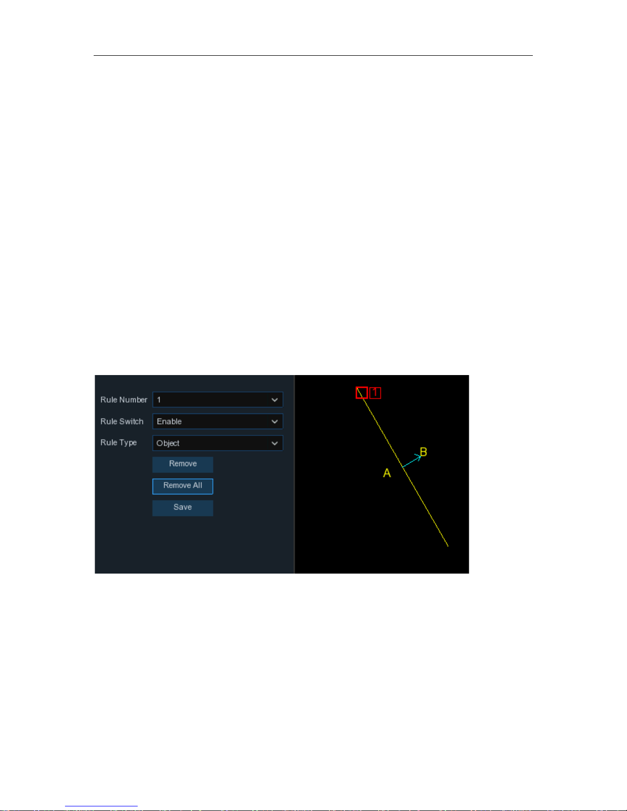
5.1.8.6 CC (Cross-Counting)
Cross-Counting function counts the t imes for moving objects or people across the virtual lines.
40
USER MANUAL
Channel
: to select the channel you want to conf igure
Switch
: to enable or disable the CC func t io n
Buzzer
: to disable or to active t he buzzer to emit an alarm tone in 10, 20, 40 o r 60 s econds when
the detection is triggered
Sensitive
: The sensitivity level is from 1 to 4, with a default value of 2. Higher sensitivity will be
easier to trigger the detection.
Scene
: Scene setting includes Indoor and Outdoor. Please choose the scene to match with the
place your camera installed.
Post Recording
: You can set how long after an event occurs that the DVR will cont inu e to record.
Latch Time
: To configure the external alarm time when the detection is triggered.
Alarm Out
: If your DVR support to connect t o external alarm device, you can set to emit an al arm
tone.
Show Message:
A letter “S” will be displayed on the screen when the intellig ent detection is
triggered.
Send Email:
If an alarm is triggered, an Email will be sent to your preset email acco unt.
Full Screen:
When the det ec t ion is triggered, the channel will be enlarged into full screen.
Record Channel:
to select the channel(s) y ou w ant to record when a detection is trigger ed.
Area:
Click [
Setup
] to draw a virtual region in the camera picture.
1.
Choose one of the Rule Number. It is the number of virtual lines you can draw. Maximum 4
lines.
2.
To enable the detection in
Rule Switch
.
3.
Choose a
Rule T ype
Object
: Will count for only movin g objects.
Pedestrian
: Will count only moving pe opl e.
4.
Use your mouse to click 2 points in the camera picture to draw a virtual line. From Side A to
Side B is Enter, fr om Side B to Side A is Exit.
5.
Click
Save
to save your settings.
6.
If you want to modify the position or length of the line, click the red box in the line, the color of
41

USER MANUAL
the line will be changed to red co lor. Lon g pres s t he le ft butt on o f your mouse to mov e the l ine,
or drag the terminals to modify the length or position of the line.
7.
If you want to remove one of the lines from the ca m era pi ctur e, clic k the re d b ox in th e line a nd
then click
Remove
button. Click
Remove All
will delete all lines.
Notice:
1)
The lines shall not be too close to the edges of the camera picture, to avoid any failure to
trigger an alarm when the target cr oss through it.
2)
The lines should be in the area that detected object can be reach.
3)
The lines shall not be set too short, to avoid any failure to trigger an alarm when the target
passes outside it.
You are able to search & view the st at ist i c al result of cross counting in
5.1.8.7 Intelligent
Analysis
.
42

USER MANUAL
5.1.8.7 Intelligent Ana lysis
The statistical result can be quer ied by Daily / Weekly / Monthly / Annual for Cross In & Cross Out .
5.1.8.8 Intelligent Schedule
In order to active the intelligent function, you need to config the schedule. The schedule will be
active in 24 hours x 7 days.
To set the schedule, choose one channel then drag the c ur sor t o m ark the slots. The sky-blue
blocks in the time slots will be active for Intelligent detections. The schedule is valid only for the
selected channel each ti me when y ou set. I f you wan t to use the s ame sched ule for ot her chann els,
use
Copy
function. Click
Save
to save your settings.
43

USER MANUAL
5.2 Record
This menu allows you to configur e the recording parameters
5.2.1 Encode
This menu allows you to configure the recording video or network transmission picture quality.
Generaly, Mainstream defines the rec ording video quanlity which will be sav ed in t he H D D;
Substream defines the video quality which is being viewed via remote acc ess, for example web
client & CMS; Mobilestream de f ines the video quality which is being viewed via remote access via
mobile devices.
Resolution
: This parameter defines how large the recorded image will be.
FPS
: This parameter d ef in es the number of frames per second the D VR will record.
Video Encode Type:
For IP camera on ly. DVR support H.264 IP camera o nly. If you choose H.265,
live view screen of the IP channel will display “Decoding Failed
”.
Bitrate Control
: Select the bitrate level. For a si m ple scene, such as a gray wall is suitable
constant bitrate (
CBR
). For more complex scene, such as a busy street is suitable variable bit r at e
(
VBR
).
Bitrate Mode:
If you want to set the bitrate by yourself, then choose
User-defined
mode. If you
want to select the predefined bitrate, choose
Predefined
mode.
Bitrate:
This parameter correspo nds t o t he speed of data transfer that the DVR will us e t o r ecor d
video. Recordings that are encoded at higher bitrates, will be of b et ter quality.
Audio:
Select this option if y ou want to record audio along with video and hav e a m icrophone
connected to the DVR or using a ca m er a w it h audio capability.
ARM:
If A RM opt i on is checked, this channel will be recorded in maximum frame rate & bitrate
when an alarm (motion or I / O alarm) happens to this channel.
44

USER MANUAL
5.2.2 Record
This menu allows you to configur e the channel recording parameters.
5.2.2.1 Record
Record Switch
: Check to enable the recor din g in t his channel.
Stream Mode
: Choose the recording qual ity. If you choose Dualstream, the system will record in
both Mainstream & Substream.
PreRecord
: If this option is enabled, the DVR starts recording a few seconds before an alarm
event occurs. Use this option if y our pr imary recording type is motion or I / O alarm b as ed.
45

USER MANUAL
5.2.2.2 Record Schedule
This menu allows you to specify w hen t he DVR records video and defines the rec ording mode for
each channel. The recor ding schedule lets you set up a schedul e l i ke, daily and hourly by normal
(continuous) recording, m ot ion r ecording, I/O alarm recording & PIR rec ording (if your DVR
supports). To set the recording mode, clic k first on th e mode rad io butt on (Nor mal, Motion, IO, PIR) ,
then drag the cursor to mark the slots. The recording schedule is valid only for one channel. If you
want to use the same recording schedule for other channels, use
Copy
function. Click
Apply
to
save your settings.
Channel
: Select the channel to set its recording parameters.
Normal
: When the time slot is marked gr een, this in dicates the cha nnel per forms nor mal record ing
for that time slot.
Motion
: When the time slot is marked yellow, this i ndicates the channel records only when a
motion is detected during t hat t ime s lot.
IO
: When the time slot is marked red, t his indicates the channel records o nly when the sensor is
triggered during that time slot .
PIR
: When the time slot is marked pur ple, this indicates the channel rec ords only when the PIR is
triggered during that time slot .
No Record
: A time slot marked black means that there is no r ecording scheduled for the time slot.
46

USER MANUAL
5.2.3 Capture
This menu allows to configur e t he image capture function.
5.2.3.1 Capture
Enable Capture
: Enable or disable auto matic capturing on the channel.
Stream Type
: Select the image resolution by mainstream or substream.
Normal Interval
: Time interval to capture an image in normal recor ding.
Alarm Interval
: Time interval to capture an image when motion, I O alarm or PIR is triggered
Manual Capture
: Enable or disable manual capture in the channel
5.2.3.2 Capture Schedule
Channel
: Select the channel to set its capture parameters.
47

USER MANUAL
Normal
: When the time slot is marked gr een, this indicates the channel performs n ormal capture
for that time slot.
Motion
: When the time slot is mar ked y ellow, this indicates the channel capture images only when
a motion is detected during t hat t ime s lot.
IO
: When the time slot is marked red, t his indicates the channel capture imag es only when the
sensor is triggered during that time slot.
PIR
: When the time slot is marked pur ple, this indicat es the chan nel capture images only w hen the
PIR is triggered during that t ime s lot.
No Capture
: A time slot marked black means that it won’t captur e any images for t he ti me slot, bu t
you can manually capture images if you enable the manual capture f unct i on in the channel.
5.3 Alarm
In these section, you can configure the alarm parameters.
5.3.1 Motion
Operation is same as 5.1.5 Motion
5.3.2 I/O
This is an optional functio n, it w ill appear if your DVR supports sensor I/O, you connect external
sensor I/O alarm devices t o w or k with t he DVR.
Alarm In:
I/O channel.
Alarm Type:
There are 3 types for your choice: Normally-Open, Nor ma l ly-Close, and OFF.
Choose the one to match y our sens or type, or choose OFF to close the sens or trigger function.
Buzzer:
The DVR can use its internal buzzer to emit an alarm tone. You can set the buzzer
duration in seconds when a sens or is t r igg er ed.
Alarm out:
Tic k to en able external alarm device to emit an al arm tone when a sensor is triggered.
Latch Time:
you can set how long the buzz er will sound when external sensor is triggere d (10s ,
20s, 40s, and 60s).
Record
: Click icon and choose which channel(s) you want t o r ecor d when the motion
detection is triggered.
48

USER MANUAL
Post Recording :
You can set how long alarm record will last when alar m ends (30s, 1minutes,
2minutes, 5minutes).
Show Message:
Display the alarm messa ges on the screen when sensor is triggered.
Send Email:
Set to send email to specified email when sensor is triggered.
Full Screen:
When sensor is triggere d, t he cor r esponding channel will be switched t o t he full
screen mode.
FTP Upload
: To upload alarm images to FTP serv er when I/O alarm is triggered. To enable FTP,
please view 5.4.4 FTP
.
5.3.3 PIR
Operation is same as
5.1.6 PIR
5.3.4 PTZ Linkage
If you had connected the PT Z cameras, you can set the linkage bet ween P TZ cameras and Mot ion
Alarm and/or external I/O sensor alarm. With the linkage function, you can turn your PTZ cameras
focus to the preset point when a motion or I/O alarm happens.
Switch
: Enable or disable the PTZ linkage function.
Motion:
Motion detection alarm w i ll trigger the PTZ linkage function it is checked.
IO:
IO alarm will trigger the PTZ l in ka ge function it is checked.
PTZ:
Click icon to associate the PTZ cameras with preset points. View preset point at
5.1.4.1
PTZ control
.
49

USER MANUAL
5.3.5 Exception
This menu allows you to set the t ype of events that you want the DVR to inform you.
Event Type
: Select the event type from below options:
-
No Space on Disk
: When an H DD is full.
-
Disk Error
: If the HDD is not detected pr operly.
-
Video Loss
: If a camera is not connected properly.
Switch
: Check the box to enable the mo nit oring of the event.
Buzzer
: Set the buzzer durat ion when the event occurs (Off/10s/20s/40s/60s). To disable buzzer,
select
OFF.
Latch Time:
This is an optional function. Determine how long the external alarm dev i ce to sound
(10s, 20s, 40s, 60s) if your DVR support to connect external alarm dev ice.
Alarm Out
: This is an optional function. Clic k to enable t he extern al a larm dev ice t o sound. This is
an optional function.
Show Message
: Check the box to display a message on the scr een when No Space on Disk, Dis k
Error , or Video Loss event happens.
Send Email
: Let the DVR to send you an auto-email when an event occurs.
50

USER MANUAL
5.4 Network
This menu allows you to conf igure netw ork para meters, such as PPP oE, DHCP, and 3G. The most
common types are DHCP. Most probably your network type is DHCP, unless the network is
manually addressed. If y ou need an authentication user name and password to the Internet, then
choose PPPoE. If you want to use mobile network connection, then choose 3G.
5.4.1 General
If you connect to a router allows t o us e DHCP, please check the
DHCP
box. The router w i ll assign
51

USER MANUAL
automatically all the net w or k par ameters for your DVR. Unless t he network is manually addres s ed
below parameters:
IP Address
: The IP addre ss ide nt ifies the DVR in the network. It consists o f fo ur groups of
numbers between 0 to 255, separat ed by periods. For example, “192.1 68. 001.100”.
Subnet Mask
: Subnet mask is a network p arameter which defines a range of IP addr esses that
can be used in a network. If IP address is like a street where you live then subnet mask is like a
neighborhood. The subnet address als o consists of four groups of numbers, separated by periods.
For example, “255.255.000.000”.
Gateway
: This address allows the DVR to access the Internet. The for mat of the
Gateway
address is the same as the
IP Address
. For example, “192.168.0 01. 001”.
DNS1/DNS2
: DNS1 is the primary DNS server and DNS2 is a backup DNS server. Usually should
be enough just to enter the D NS 1 ser ver address.
5.4.4.1 PPPoE
This is an advanced protocol that allows the DVR to connect to the netw or k m or e directly via DSL
modem.
Check the “Enable PPPO E” box , and t hen enter the User name & Password of the PPPoE.
Click
Apply
to save, system will reboot to activ e the PPPoE setting.
52

USER MANUAL
5.4.1.2 3G
This is a prior using the mobile network, you need to connect a 3G dongle to the D VR.
Enable the 3G option, enter the APN, Dial Code, User name & password according to the
instruction of your 3G dongle d evice.
Prior using the mobile network, you need to connect a 3G dongle to the DVR
5.4.1.3 Port Configura t ion
Web Port
: This is the port t hat you will use to log in remotely to the DVR (e.g. using t he Web
Client). If the default port 80 is already taken by other applications, ple ase change it.
53

USER MANUAL
Client Port
: This is the port t hat t he DVR wi ll use to send information through. If the default port
9000 is already taken by other appl ications, please change it.
RTSP Port:
Default is 554, if the default port 554 is alrea dy taken by other applications, please
change it.
UPNP
: If you want to log in remotely t o the DVR using Web Client, you need to complete the port
forwarding. Enable this option if y our router suppor ts the UPnP. You need to enable UP nP bot h, on
DVR and router. In this case, you do not ne ed to c onf igure m anual ly por t forw ar ding on y our rout er.
If your router does not suppor t UP nP, make sure the port forwarding is completed manually
5.4.2 DDNS
This menu allows you to c onf igure DDN S setti ngs. T he DD NS prov id es a stat ic addres s to si mpl ify
remote connection to your DV R. To use the DDNS, you first need to open an account on the
DDNS service provider’s web page.
DDNS
: Check to enable DDNS.
Server
: Select the preferred DD NS s er ver (DDNS_3322, DYNDNS, NO_IP, CHANGEIP,
DNSEXIT).
Domain
: Enter the domain name you created on the DDNS service provider’s web page. This will
be the address you type in the URL box when you want to c onnect r emotely to the DVR via PC.
Fox example: dvr.no-ip.org.
User/Password
: Enter the user name and pass w ord you obtained when creating an account on
the DDNS service provider’s web page.
After all parameters are entered, click
Test DDNS
to test the DDNS settings. If the test result is
“Network is unreachable or DNS is incorr ect ”, please chec k whether t he net work wor ks fi ne, or t he
DDNS information is correct or not.
54

USER MANUAL
5.4.3 Email
This menu allows you to configur e email settings. Please complete these settings if you want to
receive the system notific ations on y our emai l when an alar m is trigger ed, HD D becomes f ull, H DD
is in error state, or Video Loss occurs.
5.4.3.1 Email Configuration
Email
: Check to enable.
Encryption
: Enable if your email server requires the SSL or TLS verification. If you are not sure,
set to be
Auto.
SMTP Port
: Enter the SMTP por t of your email server.
SMTP Server:
Enter the SMTP server address of your email.
55

USER MANUAL
User Name
: Enter your email address.
Password
: Enter the password of your e ma il.
Receiver 1~3
: Enter the email address wher e you want to receive the event notifications from the
DVR.
Interval
: Configure the length of the time interval between the notification emails from the DVR.
To make sure all settin gs are correct, click
Test Em ail
. The system sends an automated email
message to your inbox. If y ou r eceived the test email, it means the configur ation parameters are
correct.
5.4.3.2 Email Schedule
You need to configure the schedule to fully implement the Email notification.
The color codes on email sched ul e have the following meanings:
Green
: Slot for Motion detection.
Yellow
: Slot for I/O Alarm (optional).
Red
: Slot for Exception (HD D fu ll, HDD error, or Video Loss).
Purple
: Slot for PIR (optional).
56

USER MANUAL
5.4.4 FTP
This menu allows you to enable F TP function to view and load captured snapshots from DVR to
your storage device over FTP.
FTP Enable
: Click to enable FTP function.
Server IP
: Enter your FTP server IP address or domain name.
Port
: Enter the FTP port for file exchanges.
Name/ Password
: Enter your FTP server user name and password.
Directory Name
: Enter the default directory name for the FTP file excha nges.
Test FTP
: Click to test the FTP settings.
57

USER MANUAL
5. 5 Device
In this section, you can configure the intern al HDD & Cloud storage function.
5. 5.1 Disk
This menu allows you to check & configure the internal HDD(s). You need to format the HDD only
at the first startup and if you repl ace a new HDD.
Format HDD
: Select the HDD you want to format and then cl ick
Format HDD
. To start formatting,
you need to enter your user name and password and then click
OK
to confirm to continue
formatting.
Overwrite
: Use this option to overwrite the old recordings on the HDD when the HDD is full. For
example, if you choose the option 7 days then only the last 7 days recordings are kept on the HDD.
To prevent overwriting an y old recordings, select
OFF
. If you have disabled this function, please
check the HDD status re gular ly, to make sur e the HDD is not full. Recording w ill be st opped if H DD
is full.
Record on ESATA
: This menu only displayed when your DVR is coming with an e-SATA port on
the rear panel. It will allow to r ecor d t he video to external e-SATA HDD to enh ance your HDD
capacity. If the e-SATA recording function is enabled, e-SATA backup function will be disable d.
If your DVR supports to install
multiple
HDDs, the
edit icon appears in your syst em, you can click it
to edit the HDD as below:
58

USER MANUAL
Disk Type:
Read-write, read-only, and redundant.
Read-write mode is the normal status for a HDD to save recording or search recording to pl ay.
To prevent important video data from being overwritten dur ing cyclic recording, the HDD can be
set as
Read-only
mode. New recording will be not able to save into this read-only HDD. You can
still search recording from t his read-only HDD to play.
A
Redundant
HDD can be used to autom at ically backup video footage on the recor ding
(read-write) hard drive. When a redunda nt HDD is set , t he syst em can be set to record ca mer as in
parallel to both the recording hard drive and the redundant hard drive in case of hard drive failure.
5.5.1.1 Disk Group
If your DVR supports to install m ult i ple HDDs, you can configure the HDD to be different groups.
HDD groups allow you to balance r ecordings across multiple hard dr iv es . For example, you can
record channels 1~4 to one har d dr ive and 5~8 to a second hard drive. This can reduce the
amount of wear on the hard drives and may extend the life of the hard drives.
1. Use the dropdown next to
Disk Group Type
to select the type of group to con figur e.
59

USER MANUAL
2. Use the dropdown next to
Disk Group
to select the specific gro up w ithin the selected group
type.
3. Click the numbered boxes representing channel s t o r ecor d channels to HDDs in the selected
group.
4. Click
Apply
to save.
5.5.1.2 S.M.A.R.T
This function can be used to disp lay t ec hni cal information on the hard drive installe d in s i de your
DVR. You can also perform a test (there are three types av ailable) to ev al uat e and detect potential
drive errors.
Whole Evaluati on not passed, contin ue to use the disk:
If for some reason the hard driv e has
developed a fault (such a s one or more bad se ctors), you can inst ruct your DVR to co ntinue sav ing
to the drive.
Self-check Type:
There are three types available:
Short:
This test verifies major com ponents of the hard drive such as read/wr ite heads, electronics
and internal memory.
Long:
This is a longer test that ver ifies t he above as well as performing a surface scan to reveal
problematic areas (if any) and forces bad sector relocation
60

USER MANUAL
Conveyance:
This is a very quick test that v er ifies t he m echanical parts of the hard drive are
working.
Note: When performing a test, your DVR will continue t o w or k as normal. If an HDD S.M.A.R.T
error found, the HDD can be continued to use, but there will be a risk to lose recording data. It is
recommended to replace a new HDD.
5.5.2 Cloud
Your DVR has the ability to upload snapshots to the cloud service via Dr opbox which is a free
service that allows you to easily store and share snapshots and alw ays have them on hand when
you need them.
Before activating the cloud fun ct ion, we recommend that you create a Dropbox account using the
same email address an d passw ord used for y our DV R. Go to www.dropbox.com, input your name,
email address and passw or d, agr ee t o t he terms & conditions then click the sign up but t on.
Cloud Storage
: Check to enable the function.
Cloud Type
: Only Dropbox is supported currently.
Alarm Detection
: Enable if you want to upload snapshots to Dropbox when the camera detects a
motion or triggered by I/ O alarm.
61

USER MANUAL
Drive Name
: Enter the cloud storage name for your DVR.
Activate Cloud
: Click to activate the function. After a shor t moment, you will see a message
on-screen. An activation link has been sent to your email (the email address which you ha d set to
receive email alerts in 5.4. 3 Email
). Check your email then cl ick the link to activate. You will be
taken to the Dropbox website. Click “Allow” to finalize the activation. Repeat these steps if you
would like to enable cloud st or age f or t he other cameras available.
5.6 System
Change general system information such as date, time and region, edit passwords and
permissions, and more.
5.6.1 General
Device Name
: Enter the desired name for your DVR. The name can include b ot h let t er s and
numbers.
Device ID
: Enter the desired ID for y our DV R. The device ID is used to ident ify t he DV R, and can
only be composed of numbers. For example, 2pcs DVRs are installed in the same place, the
Device ID is 000000 for one of the DVRs, and 111111 for another DVR. When you want to operate
the DVR with a remote controll er, both of the DVR may receive the signal from cont r oller & act at
the same time. If you want t o cont r ol only the DVR with ID 111111, you can in put the Device ID
111111 in login page with remote controller for further oper at io ns .
62

USER MANUAL
Language
: Select a language you w oul d li k e t he system menus to be displayed in. M ultiple
languages are available.
Video Format
: Select the correct video stan dar d for your region.
Menu Timeouts
: Click the drop-down menu to select the time your DVR will exit the Ma in Menu
when idle. You can also disable this by selecting “OFF” (password protection will be temporar ily
disabled).
Mode
: XVR or DVR. XVR model will al low you to add IP Cameras to the DVR. If you change the
mode from XVR to DVR, all added IP cameras will be deleted.
Show Wizard
: Click the checkbox if you would like to display the Startup Wizard each time you
turn on or reboot your DVR.
5.6.1.1 Date and Time
Date & Time
Date:
Click the calendar icon to cha nge t he date.
Time:
Click the dialogue box to change t he t ime.
Date Format
: Select the preferred date format.
Time Format
: Select the preferred time format.
Time Zone
: Select a time zone relevant t o your region or city.
63

USER MANUAL
5.6.1.2 NTP Settings
The NTP (Network Time Protocol) function allows your DVR to automatical ly sync its clock with a
time server. This gives it the ability t o c onst ant ly have an accurate time setting (your DV R wil l
periodically sync automatically).
5.6.1.3 DST Settings
The DST (Daylight Saving Time) funct i on allows you to select the amount of time that Daylight
Saving has increased by in your particular time zone or region.
Enable DST
: If Daylight Saving applies to your time zone or region, check this option to enable.
Check to enable the NTP, and select a Server
Address, click Update Now t o manu ally sync
the date & time.
Click Apply to save your settings.
When NTP function is e nabled, system will
update the system time at 00: 07: 50 per day, or
every time when the system is st arting up.
64

USER MANUAL
Time Offset
: Select the amount of time that Day l ight Saving has increased by in your t ime zone.
This refers to the differ ence in minutes, between Coordinat ed Universal T i me (UTC) and the local
time.
Enable DST:
You can select how Daylight Saving starts and ends:
Week:
Select the month, a particular day and time when Daylight Saving star t s and ends. For
example, 2 a.m. on the first Sund ay of a particular month.
Date:
Select the start date ( click the ca lendar i con), end d ate and t ime whe n Day light Sav ing starts
and ends.
Start Time / End Time
: Set the start time and end time for Daylight Saving.
5.6.2 Output Configuration
This menu allows you to configur e video output parameters.
Video Output
: To choose the output options:
LIVE-OUT
is used to configure the ma in output parameters.
SPOT-OUT
is an optional option to config the VGA spot output parameters.
65

USER MANUAL
5.6.2.1 LIVE-OUT
Choose
LIVE-OUT
from the Video Output dr op-down menu.
SEQ Mode
: Select how many video channels you would like to display when your DVR is in
sequence mode.
SEQ Dwell Time:
Enter in seconds the maximum length of time you would like to display a video
channel in sequence mod e bef or e di s playing the next video channel (300 se conds is the
maximum).
Output Resolutio n
: Select a display resolution that is suitable for your TV. 1920 x 1080 will suit
most TVs. If your DVR supports 4K out put reso lution, y ou can select either 2K (2560 x 1440) or 4K
(3840 x 2160) to take advantage of the higher resolution that your 4K TV provides.
Scale and Offset
: The DVR supp orts to adjust the size & position of the display screen to match
your monitor or TV. Click
Setup
button to adjust.
Click once or long press the le ft but t on of your mouse on the arrow to adjust the size and position,
or you can scroll the wheel of the mouse t o adjust. Clic k the right button o f y our mouse to ex it, an d
click
Apply
to save your modifications.
Cursor Hidden Delay
: Click the drop-down menu to select the time your DVR will hide the m ouse
cursor when idle. You can also disable this by selecting “OFF” ( password protection will be
temporarily disabled).
Cursor Acceleration
: To adjust the speed to move the mouse cursor.
Transparency
: Click and hold the slider left or right to change how transparent the Menu Bar and
Main Menu will appear on-sc reen. Adjust accordingly .
Scale: To adjust the size of the displayed
screen by scale.
X Offset: To move the displayed screen to left
or right.
Y Offset: To move the displayed screen t o up or
down.
66

USER MANUAL
5.6.3 Multi-user
This menu allows you to configur e the user name, password and user permission.
The system supports the follow ing account types:
•
ADMIN — System Administrator
: The administrator has full control of the system, and
can change both administ r at or and user passwords and enable/disable p assword
protection.
•
USER — Normal User
: Users only have access t o l ive viewing, search, playback, and
other functions. You may set up multiple user accounts with varying levels of a ccess to t he
system.
5.6.3.1 Changing Password
To change the password for the administrator or user accounts, click the User Edit icon . The
password has to be a minimum of 8 c har act er s and can contain a mixture of numbers and letters.
Enter your new password aga in to confirm, and then click
Save
to save your new password. You
will be required to input your old pass w or d t o aut henticate.
Password Enable:
It’s strongly r ecom m ended to enable the password to protect your privacy. If
you want to disable the password protection, please ensur e your DVR is placed in a secure place.
67

USER MANUAL
5.6.3.2 Add New Users
1. Select one of the user accounts that is cur r ently disabled, click the User Edit icon .
2. Select
Enable
from the drop-down next t o
User Enable
.
3. Click the field next to
User Name
to change the user name for t he account.
4. Select
Enable
from the drop-down next t o
Password Enable
.
5. Click the field next to
Password
to enter the desired password.
6. Click the field next to
Confirm
to reenter the password.
7. Click
Save
. You will be required to input your Admin password to authenticate.
5.6.3.3 Setting User Permissions
The administrator account is t he only account that has full control of all system functions. You can
enable or disable access to certain menus and functions of each user account.
68

USER MANUAL
1. Click the edit icon under Permission tab.
2.
Check the boxes next to any system menus or capabilities you would like the user to
access. Click
All
to check all boxes. Click
Clear
to check none of the boxes.
3.
Click
Save
to save your modifications.
69

USER MANUAL
5.6.4 Maintenance
In this section, you will be able t o sear ch & view the system log, load default s et tings, upgrade the
system, export & import system parameters and manager syst em auto reboot.
5.6.4.1 Log
The system log shows you important system events, such as motion alarms and system
warnings. You can easily create a backup file of the system log for a set time period to a USB
flash drive.
70

USER MANUAL
Log Searching a nd Backing Up:
1. Click the field next to
Start Date & Start Time
to choose the starting date & time for your
search from the on-screen calendar.
2. Click the field next to
End Date & End Time
to choose the end dat e & tim e for y our search from
the on-screen calendar.
3. Select the type of events you would like to search for from the dr opdown next to
Log Type
, or
select
All
to see the entire system log for the selected time period.
4. Click
Search
.
5. Browse system log events from your search period:
o
Video events can be played back instantly by clicking in the
Playback
column. Right-click to
return to your search resul t s.
o
Use the / buttons in the bottom-right corner of the menu to mov e bet w een pages
of system log events.
6. Click
Backup
to create a backup of the system log for your search period. Please ma ke sur e
your flash derive has been conn ect ed to the DVR’s USB port.
7. The backup drive menu appears. Navigate to the folder y ou want t he backup file to be sav ed in,
then click OK to begin.
5.6.4.2 Load Default
Reset the DVR settings to its out-of-box state. You can choose to reset all settings at once, or just
settings on specific menus. Restor ing default settings will not delete recordings and snapshots
saved to the hard drive.
Check the items you want restore, or check
Select All
to choose all items. Click
Apply
to load
default settings of your chosen items.
71

USER MANUAL
5.6.4.3 Upgrade
1. Copy the firmware file (.sw file) to your USB drive, and insert the USB flash driv e into the DVR ’s
USB port.
2. Click Select File button to choose the firmware file in your USB flash drive, then Click OK.
3. Click
Upgrade
button to start sys t em upgrade. The system upgrade will last around 5-10
minutes, please do NOT power off the DV R or r emove the USB from DVR during fir mwar e
upgrade.
5.6.4.4 Parameter Management
You can export the main menu settings you have configured to a USB flash drive, or import an
exported setting file from USB flash drive to the DVR.
Save Settings
: Click to save the DVR current system settings to the USB device. You will be
required to input the Admin password to authenticate.
Load Settings
: Once you have created a system set t ings export, you can import the settings on
another DVR. Click
Load Settings
button to
navigate to the system settings file you want to
import from your USB flash driver.
You will be required to input t he Admin password to
authenticate.
72

USER MANUAL
5.6.4.4 Auto Reboot
This menu allows the system to a uto reboot the DVR regularly. It is recommended to leave this
function enabled, as it maintains t he operational integrity of your DV R.
Auto Reboot
: Check to enable.
Time:
You can set the DVR to reboot by day, week or month.
5.6.5 IP Camera Maintain
This menu allows you to upgrad e t he I P camera’s firmware and rest or e default settings of IP
camera.
73

USER MANUAL
5.6.5.1 Upgrade IP Camera
1. Choose one of the IP cameras you w ant t o upgr ade firmware.
2. Click
Select File
select the update file from y our US B f lash dr ive, then click OK.
3. Click IPC Upgrade button to start upgrading. You will be required to input the Admin password
to authenticate. Please do NOT power off the DVR and IP camera or remove the USB during
the upgrading.
5.6.5.2 Load Default Settings for IP Camera
1. Choose the IP cameras you want to restore.
2. Click
Load Default
to restore settings. You will be required to input t he Admin password to
authenticate.
74

USER MANUAL
5.6.6 System Information
This menu allows you to view t he system information, channel information, record information &
network status.
5.6.6.1 Information
View system information such as device ID, device model na me, I P address, MAC address,
firmware version and mor e.
If your DVR supports P2P function, you will find the P2P ID & P2P QR code in the informati on
page. You can scan this QR cord with mobile app to remote v iew the DVR.
5.6.6.2 Channel Information
View channel information for each connected camera such as alias, mainstream and subst r eam
recording specifications, motion detection status & privacy zone.
75

USER MANUAL
5.6.6.3 Reco rd Information
View recording information for each connected camera such as bitrate, stream type, recording
resolution and frame rate (FPS).
5.6.6.4 Network State
View network information.
Total Band Width :
It shows the DVR’s total input band width for IP cameras.
Used Band Width:
It shows the used band width of IP cameras.
76

USER MANUAL
Chapter 6 Search, Playback & Backup
The Search function gives you t he ability t o search for and pl ay pr eviously rec orded v ideos as well
as snapshots that are stored on your DVR’s hard drive. You have the choice of playing video that
matches your recording s chedule, manual recordings or motion events only . The Backup function
gives you the ability to save i mport ant events (both video and snapshots) to a USB flash drive.
6.1 Using Search Function
Click
Search
button in the Start Menu to enter search section.
1. Search Options:
the system provides various search & playback methods: G ener al, Events,
Sub-periods, Smart & Pictur es
2. Search Date:
search by a date to play bac k.
3. Search Type:
the system provides different search types to narrow your search.
4. Channel Selection:
to choose the channels y ou want to search & play.
5. Video Playback Controls:
to control the video play back.
Enlarge the video playback to full screen
Rewind, x2, x4, x8 and x16
Slow Play, 1/ 2, 1/4 and 1/8, 1/16 speed
1
2 3 4
5 6 7
77

USER MANUAL
Play
Pause
Play frame by frame. Click once to play a frame of the video
Stop
Fast Forward, x2, x4, x8 and x16
Digital Zoom: Click to zoom in t hen click-and-drag on a camera image during playback to
zoom in on the selected area. Right-click to return to regular play back.
Video Clip. Quickly save a section of video to a U SB flash drive. View more on
6.1.1.1
Video Clip Backup
Save Video Clip.
Volume Control
: scroll the slider bar to increase or decrease volume.
Snapshots: to capture a snapshot image to y our U SB fl ash drive. If the video playback is
in split-screen v iew, move the mouse cursor to the channel you want to capture, and then
click the icon to save the snapshot.
6. Timeline:
Continuous recordings ar e shown with colored bars to represent different types of
recording (legend shown i n t he bot t om-right corner of the display). Use t he t imeframe options
( ) to view a smaller or larger time period.
Different types of recording shown in different colors:
Continuous Recording in
Green
color;
Motion Recording in
Yellow
color;
I/O Recording in
Red
color;
Motion & I/O Recording in
Orange
color;
Intelligent Recording in
Blue
color;
PIR Recording in
Purple
color;
7. Playback Status:
display the video play st at us.
78

USER MANUAL
6.1.1 Search & Play Video in General
This menu gives an option t o sear ch & play recording for a selected date.
1.
Select a date to search for video recording from the calendar.
2.
Choose a search type.
3.
Check channels you would like to search, or check
Channel
to search all connected channels.
4.
The search result will display on the timeline from 00:00 to 24:00.
5.
Click button to start playback.
6.
Control the playback with buttons on
Video Playback Contr ols.
7.
Use the timeframe options ( ) to view a sma ller or larger time period.
8.
If you want to quickly save a section of video dur i ng playing back to a USB flash drive, use t he
Video Clip
backup function.
6.1.1.1 Video Clip Backup
1.
Insert your USB flash drive to the DVR.
2.
Start a video recording playback.
3.
Click icon.
4.
Check the channel(s) you want to make a video clip backup.
5.
Move the mouse cursor to the timeline where you want to start the video clip.
79

USER MANUAL
6.
Press and hold the left button of your mouse, a nd drag the dr ag the c ursor to t he timeline w here
you want to end the video clip.
7.
The icon has been changed t o icon, click to save the video clip.
8.
Select a file type for your backup files, clic k
Save
button to save the video clips . Ple ase make
sure your USB driver has enough space to save the video clips.
9.
The backup drive menu appears. Navigate to the folder you w ant the backup files to save in.
10.
Click OK to begin. The p r ogr ess bar at the bottom of the window shows you the progress of
the backup.
80

USER MANUAL
6.1.2 Event Search, Playback & Backup
Event search lets you view a list of video recordings with the channe l, st ar t and end time, and
recording type convenientl y summarized. You can also quickly back up events to a USB flash
drive.
To search, play & back up for events:
1. Choose the date & time you want to search.
2. Check the recording types you want to search, or check Search Type to choos e al l.
3. Choose the channels you want to search, or check Channel to choose all channels.
4. Click icon to start search.
5. Events fitting your search criteria are displayed in list form. You can double click the left button
of your mouse upon one of the event s t o play the video immediately.
6. Click icons in the bottom-right corner of the menu to brows e bet w een pages
of events, or input the page you want to browse.
7. You can switch t he view of list form in by clicking bel ow icons which is show at the right bottom
corner of the screen:
Thumbnails vi e w.
You can view the snapshots of the events.
List view.
The events wil l be displayed in list.
2
10
1
3
4 5 6 7 8 9 11
81

USER MANUAL
Detailed view.
You can view the details of the events.
In the detailed view mode, you can lock the video event s to keep event s from bei ng over writt en
in the hard drive. Click the icon to lock or click to unlock the events.
8. When you click the left button of your mouse u pon one of the event, system will show the ev ent
information on the left bottom c or ner of the screen.
9. Check the box next the number of the event to select files, or check the box next
Select
to
select all events in the page.
10. The number of selected files, total size infor m at ion will be displayed at the right bottom of the
screen.
11. After selecting file, you can click icon to save the video to USB fla sh dr ive. Or click
icon into event playback cont r ol window to play the video.
6.1.2.1 Event Playback Control
1. Event List, you can select the events here.
2. Click icon to save your selected event videos to USB flash drive. Click icon to play
video.
3. Control the playback with buttons on
Video Play back Contr ols.
You can click icon or click
right button of your mouse to exit t he playback and return to event search win dow.
4
3
1 2 5
82

USER MANUAL
4. The event you are playing now will be displayed on the ti me lin e.
5. Use the timeframe options ( ) to view a smaller or lar ger t ime period.
6.1.3 Sub-periods Playback
Sub-periods playback allows you to play multiple normal recordin gs and motion events
simultaneously from a sin gle channel. With normal and event recor dings, the video is divided
evenly depending on the split-scr een mod e that has been select ed. For exa mple, if the v ideo is an
hour long and you have selected Split-screens x 4, each split-scree n w il l pl ay for 15 minutes.
To search & play video in sub-periods:
1. Choose the date & time you want to search.
2. Choose the split-screens you want the videos t o be play ed in.
3. Check the recording types you want to search, or check Search Type to choos e al l.
4. Choose the channels you want t o searc h. P lease no te t hat t his fu nctio n only s upports t o searc h
& play one channel at a time.
5. Click the play button to start playing. Control the playback with buttons on
Video Playback
Controls.
6. Videos are being played in split-screens.
7. Click the left button of your mouse upon a particular spl it -screen, the time period of the video
split-screen will be displayed on the timeline. The color bar on the top of the timel ine i ndicates
the time span of the video split-screen you have clicked. The co lor bar on the bottom of the
timeline indicates the time span for t he whole videos you have searched.
8. Use the timeframe options ( ) to view a smaller or lar ger t ime period.
6
8
1
3 7 5
4
2
83

USER MANUAL
6.1.4 Smart Search & Playback
Smart mode allows you to easily search & play the motion events in one or mor e s pecific areas of
the channel.
To start a smart search & playback:
1. Choose the date & time you want to search.
2. Check the recording types you want to search, or check Search Type to choos e al l.
3. Choose the channel you want to search, the motion recording in the selected channel wil l be
searched automatically. Please note that this function only suppor t s t o sear ch & play one
channel at a time.
4. Click the play button on the to start playing. Control the playback with buttons on
Video
Playback Controls
.
5. Videos are being played in the screen.
6. The color bar on the top of the timeline indicates the t ime span of the motion recordings you
have searched. The color bar on t he bottom of the ti meline ind icates the co mplete ti me span for
the whole recordings you have specified.
7. Use the timeframe options ( ) to view a smaller or lar ger t ime period.
5 7 4
3 1 2
6
84

USER MANUAL
6.1.4.1 Smart Search Area
The smart search function searches t he motion reco rdings in the w hole area of channe l by default.
You can specify one or more particular areas to narrow your search.
Click this ic o n on Video Pla y back Control s, t he camera will be shown in full screen and the
Smart controls bar will be visib le.
You can click and hold the edge of the cont r ols bar to reposition it.
Smart Controls Bar
Click this to define a full screen detection area
Click this to delete all areas created.
Click this to search and play video based on the areas defined.
Click this to return to the playback interface.
To define one or more specifi c ar eas, please do the following:
1. Click and drag to select the area that you want t o define. Multiple areas can be defined. You
can also use the same action to re mov e sec tions of the defined area or to delete it ent irely.
When finished, click the sear ch button to play video based on the areas d ef ined.
2. You’ll be returned back to the playback inter face. Segments matching your search cr iteria will
be shown on the timeline in blue color.
85

USER MANUAL
6.1.5 Picture Search & View
This function can be used to search, play and copy snapshots to a USB flash dr iv e.
To search, play & back up pictures:
1. Choose the date & time you want to search.
2. Check the picture capture types you want t o sear ch, or check Search T y pe to choose all.
3. Choose the channels you want to search, or check Channel to choose all channels.
4. Click button to start search.
5. Pictures fitting your search criteria are displayed in list form. You can double click one of the
pictures to get a larger view.
6. Click icons in the bottom-right corner of the menu to brows e bet w een pages
of pictures, or input the page y ou w ant to browse.
7. You can switch t he view of list form in b y clicking below icons which is show at the right bottom
corner of the screen:
Thumbnails view. You can view the snapshots of the ev ent s.
List view. The ev ent s will be displayed in list.
Detailed view. You can view the details of the events.
2
10 1 3 4 5 6 7
8 9 11
86

USER MANUAL
8. When you click the left button of your mouse upo n one of the pictures, system will show the
picture information on the le ft bot tom corner of the screen.
9. Check the box next the number of the event to select files, or check the box next
Select
to
select all pictures in the page.
10. The number of selected files, total size infor m at ion will be displayed at the right bottom of the
screen.
11. After selecting file, you can click button to save the pictures t o US B f la sh dr ive. Or click
button to go into picture preview control window.
6.1.5.1 Pic ture Preview Control
1. Picture List, you can select the pictures here.
2. Click button to save your selecte d pi c t ur es t o a USB flash drive. Click button to view
the pictures in slideshow.
3. Press button to exit preview control window and go back to pict ur e search window .
Press button to pause, press to resume slideshow.
Press button to display previous snapshot or group of snapshots, press to display the
next snapshot or group of snaps hots.
Click button to view a single snapshot at a time, click button to view four snapshots at
a time, press buttons to view nine snapshots at a time.
3
1
2
87

USER MANUAL
Chapter 7 Remote Access via Web Client
Use the Web Client to remotely access your DVR at any time via a P C. Before you access the
Web Client, you need to ensure that the internet settings of the DV R are configured properly.
7.1 Basic System Environment Requirements
The minimum requirements for hardware and OS required t o r un Web Client are given as below.
7.2
Web Plugin Download and Installati on
To access the Web Client, do the following:
For IE/Chrome/Firefox:
1.
Launch the explorer on your PC an d ent er t he DVR IP address or DDNS doma in name (Host
Name) you have set on DVR in the URL box.
2.
For the first time you run the web cl ient, s ystem will require to install the web cli ent plugin. Click
download
to download the plugin and install to your computer.
Item Minimum Recommended
CPU
Intel® Core™ i5 CPU
Intel® Core™ i5 CPU or higher
RAM 4G or more 8G or more
Hard Drive
500G or more
1000G or more
Display RAM
2G or more
4G or more
Display Resolution
1280*1024
1920*1080
OS
Windows 7 or above
Mac OS X® 10.9 or above
DirectX
DirectX 11
Direct3D
Acceleration Function
Ethernet Adapter
10/100/1000M Ethernet Adapter
IE Microsoft Internet Explorer (Ver. 11,10,9,8). It doesn ’t support Edge.
Mozilla Firefox V51 or below. It doesn’t support V52 or above ver sion.
Google Chrome V44 or below. It doesn’t support V45 or above version.
Mac Safari 5.1 or above
88

USER MANUAL
3.
After installing the plug-in, clo se & launch again your browser and repe at s t ep 1 to open the
login page. Input your user nam e and password to login the web client.
Note
: If you use Google Chrome, please use Version V41 or below. I f you use V42 to V44, you
need to enable NPAPI plugins. Please enter chrome://flags/#enable-npapi on URL bar to find and
enable NPAPI. It doesn’t support V 45 or above so far .
89

USER MANUAL
For Mac Safari:
1.
Launch the Safari in your Mac, and ent er t he DVR IP address or DDNS do main name (Host
Name) you have set on DVR in the URL box.
2.
Download the plug-in "Surveilla nceClient.dmg", locate the downloaded file and double click it.
3.
Click on "Continue" --> "Install". E nter user name and password for Mac comput er,
Click on "Install Software" --> "Close" to finish installation.
4.
Close Safari and open again to repeat s t ep 1 t o open the Web Client login page.
1
2
3
4
90

USER MANUAL
7.3 Web Client Manager
The web client supports to fully control the DVR with administrator account. Please make sure to
protect your user name & passwor d for preventing illegal login.
7.3.1 Live Interf ace
This is the first screen th at opens a fter you hav e logged i n to the Web Client. Here y ou can open o r
close live preview, record video to local comput er manually, take snapshots of the scr eens, PTZ
control, color adjustment, et c.
1- Channel List:
Open the channel list for quick camera function
Click button to display the Channel List.
Click button to hide the Channel List.
Turn the Live video stream on/off. The but ton is in blue color if the live video stream is
on.
Manual Recording buttons. Click to start manually recording liv e stream video. Click
again to stop recording. Manua l rec ordings are saved to your computer. While in
recording, the button is in blue color.
Manual
snapshot
button. Click to save a snapshot of the current live display t o your
computer.
Bitrate button. Set camera to use mainstream, substrea m or m obi le st r eam video
settings. Mobile stream is available for IP channels only.
91

USER MANUAL
2- Live Video Stre am Options:
Mainstream:
View all live videos using high-quality mainstream video settings.
Substream:
View all live videos using middle-quality substream video settings.
Mobile Stream:
View all live video using lower-quality mobile stream video settings to
conserve bandwidth. Available for IP channels only.
3- Main Menus:
Live:
View live video fro m cam er as.
Playback:
View recorded video which is saved in DVR’s HD D.
Remote Setting:
Access functions of the DVR setting menus.
Local Settings :
Set download locations for r ecordings and s napshot s taken u sing Web Client,
and choose file type for video fil es.
4- Information:
Hover over to see system detai ls.
5- Exit.
6- Color Controls. Click to display or hide the color controls.
7-
PTZ Controls:
Click to display or hide the PTZ controls for using PTZ cameras.
8-
PTZ Controls
Directional Arrows: Click to move the PTZ camera
Automatic line scan.
PTZ Speed: Click to set th e speed of the PTZ camera’s movement.
Zoom: Click –/+ to zoom in or out.
Focus:
Click –/+ to adjust focus.
Iris: Click –/+ to adjust iris.
Preset Point: Add, remove, or go to preset point.
Cruise:
Start/stop PTZ cruise
92

USER MANUAL
9- Live View Contr ol Buttons:
Open the images on Live window.
Close all the Live channels
Original Proportions: Shows live video at the original proportions
Stretch: Stretch live video to fit the full area for each channel on scre en.
To enlarge the web client to full screen.
Manual Recording: Click to st ar t manu ally recording for all displayed channels. Click
again to stop recording. Manua l r ecordings are saved to your computer.
Snapshot: Click to save snapshots of all current displayed channels to your computer.
Digital Zoom: Click upon on a live image, then click-and-dra g over an area of the live
image to enlarge. Right-click to r et ur n t o the normal display.
Volume Control. Volume is mute.
10- Navigation:
Shows current page number f or the channels shown on screen. Use the arr ow
keys to switch between pa ges.
11- Page View: Click to select how many channels appear on screen at a t ime.
7.3.2 Playback
You can search & play recording videos stored in the HDD inside the DVR, and download the
videos to your computer.
93

USER MANUAL
To search recordings:
1. Click Playback in the top-right corner of the window.
2. Select a day on the ca lendar to search for recordings from. Day s with recordings appear with
a red underline.
3. Select the record in g t ype to search for from the dropdown next to Type, or select All to
search for all recordings.
4. To choose the video stream you want to search & play . I f you want to play Substream
recordings, please make sure you had set the DVR to record with Dua lst ream at
5.2.2.1
Record.
5. Check the chann els y ou would like to search for recordings fr om. Check Synchronous
playback to play all channels at once.
6. Click Search.
7. Recordings that fit y our se arch wil l be dis played in th e timel ine. Click a sec tion of v ideo w here
you would like to begin playback and click the play button.
7.3.2.1 Playback Control Buttons
Play the recordings
Pause
Stop
Go Forward One Frame:
Move frame-by-frame through playback. Only available when the
Synchronous pla yback
option is not checked.
94

USER MANUAL
Click upon one of the channels which is being played and t hen click record button to record
current video to your comput er. Click again to stop recording.
Click upon one of the channels which is being played and t hen click capture button to take a
snapshot and save to your com put er.
Opens the Download menu, which allows you t o download several video recordings at onc e.
Choose the files you want t o dow nload, press
Start Download
button to begin, you will see the
download status. Press
Stop Download
button to stop.
Playback Speed.
Click to choose the playing speed.
Play All Channels:
Click to play all channels y ou have chosen to searched. Only available
when the
Synchronous p lay bac k
option is not checked.
Stop All Channels:
Click to stop playing all channels. Only available when the
Synchronous pla yback
option is not checked.
Digital Zoom: Click upon on a playing video, then click-and-drag over an area of the video to
enlarge. Right-click to return to the normal display.
Original Proportions: Shows the playing v ideo at the original proportions
Stretch: Stretch the playing video to fit the full area for each channel on screen.
To enlarge the web client to full screen.
95
 Loading...