


User manual
UM EN VALUELINE IPC
Order No.: 9047058
Valueline industrial PC
Installation and configuration

User manual
Valueline industrial PC Installation and configuration
2012-06-05
Designation:
Revision:
Order No.:
This user manual is valid for:
Designation Version Order No.
Valueline IPC 2913108
UM EN VALUELINE IPC
D
9047058
2637_en_D PHOENIX CONTACT

Please observe the following notes
User group of this manual
The use of products described in this manual is oriented exclusively to:
– Qualified electricians or persons instructed by them, who are familiar with applicable
standards and other regulations regarding electrical engineering and, in particular, the
relevant safety concepts.
– Qualified application programmers and software engineers, who are familiar with the
safety concepts of automation technology and applicable standards.
Explanation of symbols used and signal words
This is the safety alert symbol. It is used to alert you to potential personal injury
hazards. Obey all safety measures that follow this symbol to avoid possible injury or death.
There are three different categories of personal injury that are indicated with a
signal word.
DANGER This indicates a hazardous situation which, if not avoided, will re-
sult in death or serious injury.
WARNING This indicates a hazardous situation which, if not avoided, could
result in death or serious injury.
CAUTION This indicates a hazardous situation which, if not avoided, could
result in minor or moderate injury.
This symbol together with the signal word NOTE and the accompanying text
alert the reader to a situation which may cause damage or malfunction to the
device, hardware/software, or surrounding property.
This symbol and the accompanying text provide the reader with additional information or refer to detailed sources of information.
How to contact us
Internet Up-to-date information on Phoenix Contact products and our Terms and Conditions can be
found on the Internet at:
www.phoenixcontact.com
Make sure you always use the latest documentation.
It can be downloaded at:
www.phoenixcontact.net/catalog
Subsidiaries If there are any problems that cannot be solved using the documentation, please contact
your Phoenix Contact subsidiary.
Subsidiary contact information is available at
Published by PHOENIX CONTACT GmbH & Co. KG
Flachsmarktstraße 8
32825 Blomberg
GERMANY
Should you have any suggestions or recommendations for improvement of the contents and
layout of our manuals, please send your comments to:
tecdoc@phoenixcontact.com
www.phoenixcontact.com.
PHOENIX CONTACT

Please observe the following notes
General terms and conditions of use for technical documentation
Phoenix Contact reserves the right to alter, correct, and/or improve the technical documentation and the products described in the technical documentation at its own discretion and
without giving prior notice, insofar as this is reasonable for the user. The same applies to any
technical changes that serve the purpose of technical progress.
The receipt of technical documentation (in particular user documentation) does not constitute any further duty on the part of Phoenix Contact to furnish information on modifications
to products and/or technical documentation. You are responsible to verify the suitability and
intended use of the products in your specific application, in particular with regard to observing the applicable standards and regulations. All information made available in the technical
data is supplied without any accompanying guarantee, whether expressly mentioned, implied or tacitly assumed.
In general, the provisions of the current standard Terms and Conditions of Phoenix Contact
apply exclusively, in particular as concerns any warranty liability.
This manual, including all illustrations contained herein, is copyright protected. Any
changes to the contents or the publication of extracts of this document is prohibited.
Phoenix Contact reserves the right to register its own intellectual property rights for the
product identifications of Phoenix Contact products that are used here. Registration of such
intellectual property rights by third parties is prohibited.
Other product identifications may be afforded legal protection, even where they may not be
indicated as such.
PHOENIX CONTACT

Table of contents
1 Overview................................................................................................................................. 1-1
1.1 Getting acquainted with the VL IPC ....................................................................1-2
1.1.1 Status LEDs ........................................................................................1-5
2 Installation............................................................................................................................... 2-1
2.1 Mounting and clearances ...................................................................................2-1
2.1.1 Temperature specifications .................................................................2-1
2.1.2 Wall-mount and bookshelf installation .................................................2-2
2.1.3 Panel mount ........................................................................................2-3
2.2 Interfaces............................................................................................................2-6
2.2.1 Communication interfaces ..................................................................2-7
2.2.2 External display ...................................................................................2-7
2.2.3 Installing PCI cards .............................................................................2-8
3 Startup and Operation ............................................................................................................ 3-1
3.1 Power ................................................................................................................3-1
3.2 Power switch ......................................................................................................3-2
3.3 Software license and activation ..........................................................................3-2
3.4 Firmware and software updates..........................................................................3-3
3.5 Touchkit..............................................................................................................3-3
3.5.1 Touchkit…Setting ...............................................................................3-4
3.5.2 Touchkit… Tools .................................................................................3-7
3.5.3 Touchkit… Edge Compensation .......................................................3-11
3.5.4 Touchkit… Hardware ........................................................................3-13
3.5.5 Touchkit… About ..............................................................................3-14
3.5.6 Touchkit (eGalaxTouch) icon ............................................................3-14
3.6 On-screen Tools...............................................................................................3-15
3.6.1 Brightness Control ............................................................................3-15
3.6.2 Right-Click tool ..................................................................................3-16
3.6.3 On-Screen Keyboard ........................................................................3-17
®
3.7 Intel
Graphics Media Accelerator user interface.............................................3-18
3.7.1 User interface ....................................................................................3-18
3.7.2 Single Display configuration ..............................................................3-20
3.7.3 Multiple Display configuration ...........................................................3-22
3.7.4 Adjusting 3D operation ......................................................................3-25
3.7.5 Configuring video overlay ..................................................................3-26
3.7.6 Schemes ...........................................................................................3-26
3.7.7 Hot Keys ...........................................................................................3-27
3.7.8 Zoom ................................................................................................3-28
3.7.9 Graphics Information ........................................................................3-29
2637_en_D PHOENIX CONTACT i

Valueline IPC
3.8 Uninterruptable power supply...........................................................................3-30
3.8.1 Power supply recommendations .......................................................3-31
3.8.2 QUINT-DC-UPS… installation ..........................................................3-31
3.8.3 TRIO-UPS… installation ...................................................................3-37
3.9 Accessing the optical drive ...............................................................................3-38
3.10 Using CompactFlash cards ..............................................................................3-39
4 Maintenance........................................................................................................................... 4-1
4.1 VL IPC components............................................................................................4-2
4.1.1 Real-time clock battery ........................................................................4-5
4.1.2 Hard disk drive ....................................................................................4-5
4.2 BIOS configuration .............................................................................................4-6
4.2.1 Boot options ........................................................................................4-6
4.2.2 Power on after power fail options ........................................................4-7
4.3 Troubleshooting..................................................................................................4-8
4.3.1 Video driver .........................................................................................4-8
4.3.2 QUINT-DC-UPS… and Valueline IPC (Windows XP) ..........................4-8
4.3.3 Miscellaneous solutions ......................................................................4-9
A Product data ........................................................................................................................... A-1
A 1 Ordering data.................................................................................................... A-1
A 2 Technical data .................................................................................................. A-1
B Appendices............................................................................................................................. B-1
B 1 List of figures .................................................................................................... B-1
B 2 List of tables ..................................................................................................... B-5
PHOENIX CONTACT 2637_en_D
ii

1 Overview
Overview
The Valueline industrial personal computers is a general purpose modular design that can
be manufactured to a wide variety of application requirements. There are three processor
options: Celeron
®
, Core™2 Duo and Atom™ when ordering a Valueline IPC.
Standard hardware features for all Valueline IPC systems include:
– 24 V DC operation
– Fanless operation
– Uninterruptable power supply interface
– VGA output
– 4 USB ports
– 1 COM port (RS-232, 9-pin D-SUB connector)
– Two integrated 10/100/1000 Ethernet ports with independent MAC addresses
– Power, HDD, Run and Error LEDs
Configuration options include:
– Display size or no display
– RAM memory
– No operating system or a Windows
®
operating system
– Size and type of mass storage
– Front bezel with or without USB slot
– Mounting options
– NVRAM (non-volatile RAM–only available in some configurations)
Available depending on configuration
– DVI-D video output
– Optical storage
– 2 PCI expansion slots
– 1 or 2 CompactFlash
®
slots
This manual describes the possible options and features of the Valueline IPC available at
the time of printing. For specific part numbers and components, refer to the configuration
sheet included with the unit to determine the installed options.
In some mounting orientations, the labels with the model number, product serial number,
and the Microsoft
®
Windows® operating system product key are hidden. Copy the
information from these labels before mounting the VL IPC. It’s a good idea to write this
information on the inside cover of this manual.
2637_en_D PHOENIX CONTACT 1-1

Valueline IPC
1.1 Getting acquainted with the VL IPC
Depending on configuration options selected, the VL IPC may look different. Also, the
various mounting options provide tremendous flexibility.
Figure 1-1 shows the connector side of the VL IPC including an optional optical storage
device, which installs in the basic system, and the optional PCI slots.
Serial Port
CompactFlash
Slot 0
Optional
Optical Storage
Device
CompactFlash
Slot 1 Eject Button
CompactFlash
Slot 1
Access Door
Catch
Removable
Hard Disk
RTC Battery
X10 COM1 X9 VGA
X8 DVI D
X4 USBX6 USB
X3 ETH X2 ETH
876
9
X1: PWR 24VDC
1
2
3
4
5
1
X10 COM1 X9 VGA
2
3
876
4
9
5
VGA Video
PCI Slot 1
ERROR RUN HDD PWR
ERROR RUN HDD PWR
Status LEDs
X8 DVI D
DVI-D
X7 USB
X7 USB
USB Ports (4)
X5 USB
Press Here
to open
Access Door
X4 USBX6 USB
PUSH
X3 ETH X2 ETH
X5 USB
Ethernet Ports
PCI Slot 0
Power Switch
X1: PWR 24VDC
+– AB
Heat Sink
(entire back)
+– AB
24 V DC
Power Connector
Access Door Open Access Door Closed
Figure 1-1 Valueline IPC with Core™2 Duo or Celeron® processor and optional PCI
slots
PHOENIX CONTACT 2637_en_D
1-2

CompactFlash
Slot 0
CompactFlash
Slot 1 Eject Button
CompactFlash
Slot 1
X9 COM
X8 VGA
6
87
9
13
2
4
5
Overview
13
6
X9 COM
2
87
4
9
5
Serial Port
ERROR
RUN
HDD PWR
X8 VGA
ERROR
RUN
HDD PWR
Status LEDs
VGA Video
Access Door
Catch
Removable
Hard Disk
RTC Battery
X7 USB
X4 USBX6 USB
X5 USB
USB Ports (4)
Press Here
X4 USBX6 USB
PUSH
to open
X3 ETH X2 ETH
Access Door
X3 ETH X2 ETH
Ethernet Ports
X1: PWR 24VDC
+– AB
X1: PWR 24VDC
+– AB
24 V DC
Power Connector
Access Door Open
Access Door Closed
Figure 1-2 VL IPC with Atom processor in Atom enhanced chassis
X7 USB
X5 USB
Power Switch
Heat Sink
(entire back)
2637_en_D PHOENIX CONTACT 1-3

Valueline IPC
CompactFlash
Slot 1 Eject Button
CompactFlash
Slot 1
X9 COM
X8 VGA
6
87
9
13
2
4
5
Serial Port
13
6
X9 COM
2
87
4
9
5
ERROR
RUN
HDD PWR
X8 VGA
ERROR
RUN
HDD PWR
Status LEDs
VGA Video
Access Door
Catch
RTC Battery
X7 USB
USB Ports (4)
X4 USBX6 USB
X3 ETH X2 ETH
X5 USB
Press here
to open
Access Door
X4 USBX6 USB
PUSH
X3 ETH X2 ETH
Ethernet Ports
X1: PWR 24VDC
+– AB
+– AB
24 V DC
Power Connector
Access Door Open
Access Door Closed
Figure 1-3 VL IPC with Atom processor in Atom standard chassis
X1: PWR 24VDC
X7 USB
X5 USB
Power Switch
Heat Sink
(entire back)
PHOENIX CONTACT 2637_en_D
1-4

Overview
X8 DVI D
ERROR RUN HDD PWR
1.1.1 Status LEDs
There is a set of four LEDs.
Figure 1-4 LED layout
Table 1-1 LED status indicators
LED Indication Description
ERROR Yellow
Red
RUN Reserved for future use
HDD Flashes
green
PWR Green When 24 V DC is applied and the power switch is turned
Indicates reduced performance due to processor
temperature
Indicates an over temperature condition has caused the
processor to shut down
Indicates hard drive activity
On
2637_en_D PHOENIX CONTACT 1-5

Valueline IPC
PHOENIX CONTACT 2637_en_D
1-6

2 Installation
Installation
The flexibility of the Valueline IPC allows many different installation options.
2.1 Mounting and clearances
Depending on the configuration ordered, there are several ways to mount the VL IPC. Use
the appropriate section below to mount the VL IPC.
NOTE:
Install the VL IPC with adequate clearance around the heat sink to provide sufficient air
flow such that ambient temperatures do not exceed the operating limits listed in
Section 2.1.1, “Temperature specifications”. Install cooling fan(s) in the enclosure, if
necessary.
When installing the VL IPC in a cabinet, follow these general rules:
– Verify clearances within the cabinet. Typically, leave at least 5 cm (2 in.) on each side
with 12.7 cm (5 in.) on the connector side if the VL IPC has the optional optical storage
drive.
– Drill all holes and make all cuts before beginning installation. Be sure to protect already
installed components from shavings.
– Supporting panels must be at least 14 gauge to provide proper support.
– Make sure that there is adequate space around the heat sink (on the back of the VL IPC)
and air inlets and outlets to provide sufficient cooling.
2.1.1 Temperature specifications
Operational temperature limits depend on the specific configuration of the Valueline IPC
(see Table 2-1 “Temperature limits” for details).
Table 2-1 Temperature limits
Configuration Ambient range (operating)
Any processor with no display, 12-, 15- or 17-in.
display, solid state drive or CompactFlash
Any processor with no display, 12-, 15- or 17-in.
display and rotating hard drive
Any processor with 19- or 24-in. display, solid
state drive or CompactFlash
Any processor with 19- or 24-in. display and
rotating hard drive
Please be aware that adding PCI cards can add heat to the system.
®
card
®
card
-20°C … 55°C (-4°F … 131°F)
5°C … 55°C (41° … 131°F)
0°C … 50°C (32° … 122°F)
5°C … 50°C (41° … 122°F)
2637_en_D PHOENIX CONTACT 2-1

Valueline IPC
NOTE:
Exceeding the system temperature limits can result in performance degradation of any or
all components. It is therefore important that the ambient temperature of the installation
environment is kept within the system temperature limits of your Valueline IPC.
2.1.2 Wall-mount and bookshelf installation
Wall mounts are valid for VL IPCs that do not include a display. Use this type of mounting to
install the VL IPC on the inside of a cabinet. The VL IPC can be attached to a flat surface in
either a wall mount or bookshelf orientation. Either way, attach the unit using the four key
holes. The mounting surface must be flat and not subject to vibration.
289.0 mm
(11.4 in.)
50.0 mm
(2.0 in.)
24.0 mm
(0.9 in.)
(5.5 in.)
140.0 mm
(11.0 in.)
280.0 mm
X10 COM1 X9 VGA
ERROR
RUN
X8 DVI D
HDD PWR
X7 USB
X5 USB
X4 USBX6 USB
PUSH
X3 ETH X2 ETH
X1: PWR 24VDC
+–AB
With PCI
Slots
X10 COM1 X9 VGA
ERROR
RUN
X8 DVI D
HDD PWR
X7 USB
X5 USB
X4 USBX6 USB
PUSH
X3 ETH X2 ETH
X1: PWR 24VDC
+–AB
Without PCI
Slots
Figure 2-1 Wall and bookshelf mounts
To install a wall mounted VL IPC, follow these steps:
1. Use the VL IPC as a template and mark the locations of the key holes on the mounting
surface.
NOTE:
The unit must be installed with the small end of the key hole oriented up.
2. Use the correct anchor type for the mounting surface and securely attach the VL IPC to
the wall. Anchor hardware must be smaller than 6 mm. Ensure the attaching hardware
is in the small section of the key holes.
3. Tighten mounting screws. Be careful not to overtighten the attachment hardware.
PHOENIX CONTACT 2637_en_D
2-2

Installation
2.1.3 Panel mount
Panel mounts are the only valid mounting system for VL IPCs with a display. This mounting
system permits installation of the VL IPC in a cabinet so the display panel is visible on the
outside (see Figure 2-2).
NOTE:
Connectors and switches must be accessible from the rear. A wall panel thickness of at
least 1.9 mm (14 ga.) is required for correct mounting with IP65 protection
Cabinet wall
INSPIRING
INNO
VA
TIONS
VL IPC
Figure 2-2 Panel mount
2637_en_D PHOENIX CONTACT 2-3

Valueline IPC
1. Cut a hole in the enclosure according to the dimensions for the selected display.
X
Y
Figure 2-3 Panel cut-out dimensions for displays
Table 2-2 Cutout dimensions
Display size X (mm) Y (mm)
12 in. 334.0 253.0
15 in. 386.6 285.6
17 in. 424.0 329.5
19 in. 443.0 360.0
24 in. 620.4 352.8
2. From the front, push the VL IPC through the opening. Ensure the gasket is properly
positioned in the groove.
PHOENIX CONTACT 2637_en_D
2-4

Installation
3. From the rear, place the display clamps, 1, in the slots, 2, on the display and slide the
clamp to the right (see Figure 2-4). Clamps must be used in every slot.
1
2
Figure 2-4 Panel mount clamps
4. Tighten the screws with a screwdriver on all clamps, alternating from one side to the
other until the front bezel is secure against the panel. Torque the bolts to 1.2 Nm.
2637_en_D PHOENIX CONTACT 2-5

Valueline IPC
2.2 Interfaces
After mounting the VL IPC, make any necessary cable connections. Depending on the
mounting method, connections are made at the rear or bottom of the VL IPC (see
Figure 2-5). If the Valueline computer includes PCI slots, additional connections may be
required to the PCI cards inserted in the PCI slots.
1
X10 COM1 X9 VGA
2
3
876
4
9
5
Serial Port
PCI Slot 1
VGA Video
X9 COM
6
87
9
13
2
4
5
X8 DVI D
X4 USBX6 USB
X3 ETH X2 ETH
+– AB
X1: PWR 24VDC
X7 USB
X5 USB
ERROR RUN HDD PWR
X8 VGA
ERROR
RUN
HDD PWR
DVI-D
X7 USB
USB Ports (4)
X4 USBX6 USB
PUSH
X3 ETH X2 ETH
X5 USB
Ethernet Ports
PCI Slot 0
X1: PWR 24VDC
+– AB
Core2 Duo and
Atom Processor
Celeron Processor
Figure 2-5 Interface connections
PHOENIX CONTACT 2637_en_D
2-6

Installation
2.2.1 Communication interfaces
Various ports and connections allow the VL IPC to communicate with other devices. The
connections available on the IPC module are
– Ethernet: Two RJ45 connectors are located on the rear of the VL IPC. These allow the
computer to communicate on a 10/100/1000 Base-T Ethernet network.
– Serial: Serial devices connect to the DB-9 RS-232 port.
– USB: USB devices connect using Type A connectors. The VL IPC has four USB ports.
– VGA: This port connects the VL IPC to an external analog display with a corresponding
VGA connector.
– DVI-D: This port connects the VL IPC to an external digital display with a corresponding
DVI-D connector.
2.2.2 External display
External displays can be connected to the VL IPC to function as a desktop extension or as
an auxiliary display. Use the VGA port for analog displays and DVI-D port for digital displays.
(see Figure 2-5).
Extended Display Identification Data (EDID) displays will download its capabilities to the
display driver while non-EDID displays will not. In either case, additional settings can be
applied through the Intel
Accelerator user interface” on page 3-18).
®
Graphics Media Accelerator (see “Intel® Graphics Media
NOTE:
The VL IPC DVI-D port only passes digital signals; therefore, connecting an analog display
to the DVI-D port and using a VGA to DVI adapter will not work.
2637_en_D PHOENIX CONTACT 2-7

Valueline IPC
2.2.3 Installing PCI cards
Installing a PCI card in the optional PCI slots is done as follows:
NOTE:
Use standard ESD precautions when removing or installing PCI cards to avoid damage to
the cards and the VL IPC.
The PCI card option is not available with the Atom standard chassis.
1. Ensure the card does not exceed the maximum dimensions for the intended slot (see
“Computer data” on page A-2).
2. Remove power from the unit.
1
2
PCI Slot 0
PCI Slot 1
3
Figure 2-6 Cover removal
3. Place the unit on a soft cloth on a flat, horizontal surface with the ribbed surface (cover)
up.
4. Remove the four Phillips-head screws, 1, from the cover, 2, and remove the cover.
®
Do not remove the tamper-proof (Torx
PHOENIX CONTACT 2637_en_D
2-8
) screws, 3.

Installation
5. PCI card installation can be in slot 1 (see below), slot 0 (see “For PCI slot 0:” on
page 2-10) or both.
When installing two cards of the same type, drivers often assign higher priority to the card
in the lower slot number.
– For PCI slot 1:
a) Remove the four Phillips-head screws, 1, securing the left side panel, 2, and
remove the panel.
2
6
PCI Slot 1
4
3
1
1
5
Figure 2-7 Side panel and bracket removal
b) Remove the retaining screw and washer, 3, securing the bracket, 4. Remove the
bracket from the bracket frame, 5.
c) Line up the card’s connectors with the PCI slot connector, 6. Carefully push the
card into the connector. After it is fully inserted in the connector, the card bracket
should be aligned with the bracket frame.
d) Insert the retaining screw and washer, 3, previously removed and tighten to secure
the card.
e) Re-install the left side panel, 2, using the four Phillips-head screws previously
removed in step a).
2637_en_D PHOENIX CONTACT 2-9

Valueline IPC
– For PCI slot 0:
a) Remove the two Phillips-head screws, 1, holding the bracket frame, 2. Remove the
bracket frame and bracket, 3, as an assembly.
b) Remove the retaining screw and washer, 4, and remove the bracket from the
bracket frame.
Figure 2-8 PCI slot 0 removal
4
5
PCI Slot 0
3
2
1
PHOENIX CONTACT 2637_en_D
2-10

Installation
1
Figure 2-9 PCI slot 0 card installation
2
3
c) Attach the PCI card, 1, to the bracket frame, 2, and secure it with the retaining
screw and washer previously removed.
d) Position the PCI card and frame assembly so the frame assembly rests on top of
the vibration reduction strip. Carefully push the card into the connector, 3, ensuring
the frame assembly aligns with the mounting holes in the chassis and the card is
properly seated in the connector.
e) Secure the bracket frame to the chassis using the two Phillips-head screws
previously removed in step a).
NOTE:
Tighten all screws on the VL IPC frame to no more than 7 Nm torque.
6. Re-install the top cover, and replace and tighten the four screws previously removed.
7. Reconnect power to the VL IPC.
8. Start the VL IPC.
2637_en_D PHOENIX CONTACT 2-11

Valueline IPC
PHOENIX CONTACT 2637_en_D
2-12

3 Startup and Operation
X
3
E
T
H
X
2
E
TH
POWER: 24 VDC
+
–
A
B
3.1 Power
CAUTION:
The VL IPC is set to automatically power-up and boot after a valid power connection is
made as a default BIOS setting; to change this setting, see “Boot options” on page 4-6.
Connect 24 V DC power (see Figure 3-1) to the included removable power connector
(Order No. 1778001). This connector supports wire sizes from 0.2 to 2.5 mm² (24 to
12 AWG). Tighten the wire retaining screws using 0.5 Nm (4.4 lb
Startup and Operation
-ft) torque.
f
Ground screw
UPS (B)
UPS (A)
0 V (-)
24 V DC (+)
Figure 3-1 VL IPC power connection
The power connector pins A-B are to be used with an uninterruptable power supply (see
“Uninterruptable power supply” on page 3-30).
Ground screw
The ground screw provides an earth ground for the VL IPC.
NOTE:
Circuit ground (0 V) and earth ground are tied together. This grounding scheme may not
meet SELV and PELV European standards.
2637_en_D PHOENIX CONTACT 3-1

Valueline IPC
3.2 Power switch
With all components and I/O properly connected, press the power switch in the direction of
the dot and release it. It is a momentary switch and returns to its original position. To turn
power off, press and hold the switch for about one second and then release it to perform an
orderly shutdown of the Windows operating system.
AB
–
+
POWER: 24 VDC
X5 USB
X7 USB
PWR
HDD
RUN
ERROR
D
I
DV
X8
A
X9VG
1
M
O
C
0
1
X
X4 USB
X6 USB
X2 ETH
X3 ETH
Power switch
Figure 3-2 Power switch
The first time the VL IPC boots, the Windows operating system displays the software license
and activation (see “Software license and activation” on page 3-2). Upon completion of
boot-up, the VL IPC runs the Touchkit screen calibration (see “4 Points Calibration” on
page 3-8).
3.3 Software license and activation
Use of the Microsoft® operating system is subject to the licensing limitations specified by
the Microsoft Software License. Phoenix Contact is not responsible and cannot be held
liable for proper use of the operating system or any other software installed on the computer
unless that software is a product developed and manufactured by Phoenix Contact.
PHOENIX CONTACT 2637_en_D
3-2

Startup and Operation
To reduce software piracy and provide customers with quality service, Microsoft includes a
product activation requirement on some software, including some operating systems. Use
of the software is limited to the first 30 days after first launching the software unless the
product activation process is completed. A pop-up program prompts the user to begin the
process when the software is first started. If activation is not completed, the software
repeats the product activation pop-up on a pre-determined cycle. Once started, message
boxes lead the user through the process to obtain proper product activation.
Additional details are included in the Microsoft Software License and are also available at
www.Microsoft.com.
The Windows product key is on a sticker that is affixed to the VL IPC.
3.4 Firmware and software updates
From time to time, Phoenix Contact may make updates available for the firmware and
software utilities used in the Valueline products. These updates can be found at the Phoenix
Contact download center at
www.phoenixcontact.net/catalog.
Enter the part number or description of the device (Valueline) in the search field and
navigate to the appropriate product from the search results. Click the “Downloads” link for a
list of available downloads.
TouchKit icon
eGalaxTouch
icon
3.5 Touchkit
Valueline computers equipped with a display include Touchkit, a software utility to configure
the operation of the touch screen. This utility provides several touch screen calibration
methods as well as modes for pointer (mouse) operation and audio touch
acknowledgement.
1. To start Touchkit utility do one of the following:
Windows XP
– Double-click the “Touchmon” icon (see “Touchkit (eGalaxTouch) icon” on page 3-14).
– Click the “Start” button, navigate to the “All Programs, Touchkit” folder and then click the
“Configure Utility” icon.
– Click the “TouchKit” icon on the desktop.
Windows 7
– Double-click the “eGalaxTouch” icon (see “Touchkit (eGalaxTouch) icon” on
page 3-14).
– Click the “Start” button, navigate to the “All Programs, eGalaxTouch” folder and then
click the “Configure Utility” icon.
When Touchkit tool functions are the same for Windows XP and Windows 7 operating
systems, Windows XP examples are shown.
2637_en_D PHOENIX CONTACT 3-3

Valueline IPC
2. The “Touchkit: USB Controller… General” dialog box opens. This displays all the touch
screen controllers installed.
The default controller for the VL IPC is USB Controller.
3. If multiple controllers are installed, click the icon of the controller to be modified before
clicking the desired tab.
3.5.1 Touchkit…Setting
The “Setting” tab allows modification of the audio acknowledgement and mouse mode
features.
Figure 3-3 “Touchkit… Setting” dialog box
Audio acknowledgement
For a VL IPC with audio capability, four different modes are available when an audio
acknowledgement to a screen touch is desired. Click the desired check box to activate the
desired mode.
– Beep On Touch: A beep is sounded when the screen is touched.
– Beep On Release: A beep is sounded when the screen touch is released.
If Beep on Touch and Beep on Release are both checked, every touch will generate two
beeps.
– Beep From System Beep: Sound is generated from internal speaker (not applicable to
Valueline IPC).
– Beep From Sound Card: Sound is generated from an external speaker.
The frequency and duration of the beep can be modified using the two sliders.
– Frequency: Move the slider to the left for a lower tone; to the right for a higher tone.
PHOENIX CONTACT 2637_en_D
3-4

Startup and Operation
– Duration: This adjusts the time between beeps when Beep On Touch and Beep On
Release are both checked. Move the slider to the left for the beep occur immediately
upon the release. Move the slider to the right for the beep to be delayed to a maximum
of 1 second after the release.
Linearization Style
Normal calibration uses four touch points to calibrate the screen. A greater accuracy of the
calibration can be achieved if more touch points are used in the calibration. Chose a
linearization style of either 9 or 25 points.
To start the linearization function, click the “Tools” tab and then click the “Linearization”
button.
Double Click Time
To adjust the time span that two touches are recognized as a double-click. This range is
approximately 0.25 to 1 second.
Double Click Area
This adjusts the size of the area allowed for the second click relative to the first click.
Mouse modes
Mouse modes allow configuration of mouse (touch) behavior. One of five modes can be
activate (Figure 3-3 shows the button with “Normal Mode” active). The available modes are:
– Normal Mode: emulates normal mouse button behavior
– A touch and release acts as a click and release.
– A touch, drag and release acts as a click, drag and release.
– A constant touch behaves like a mouse button held down. If the Enable Auto Right
Click function is checked, it will act as a right-click.
– Click on Touch: emulates a left mouse button click when the screen is touched
– Click On Release: emulates a left mouse button click when the screen is touched and
released.
– Click On Touch Without Moving cursor: moves the cursor to the touched position and
acts as a normal left click but will not perform a drag to another screen position.
– Click On Release Without Moving cursor: emulates a left mouse button click when a
screen touch is released, but the cursor doesn't move to the touched point until the
touch is released.
2637_en_D PHOENIX CONTACT 3-5

Valueline IPC
Although the modes are predefined, each mode can be manually modified by clicking the
“Option” button.
Figure 3-4 Mouse mode “Option” dialog box
Click the check box of the desired functionality.
– Enable Constant Touch: Enables the “Constant Touch Area” slider to
increase/decrease movement granularity (values are displayed in pixels). Unchecked
provides smooth movement while checked with the slider to the right provides the
coarsest movement.
– Enable Auto Right Click: Enables the “Auto Right Click Time” slider to set the time
required for the a touch to be held and recognized as a right click. This requires the
“Auto Right Click” option to activated using Touchmon.
– Enable Touch: Enables or disables the touch feature of the touch screen.
– Enable Cursor Stabilization: When checked, this creates a slight lag in the cursor when
following linear movement.
– Constant Touch Area: Sets the granularity of the Constant Touch function.
– Auto Right Click Time: Sets the required touch time span when using the Auto Right
Click function is enabled.
PHOENIX CONTACT 2637_en_D
3-6

Startup and Operation
3.5.2 Touchkit… Tools
The “Tools” tab provides access to several tools for calibration and testing of the touch
screen functionality.
Figure 3-5 “Touchkit… Tools” dialog box
2637_en_D PHOENIX CONTACT 3-7

Valueline IPC
4 Points Calibration
Basic calibration can be completed using this utility. Click the “4 Points Calibration” button
to start. The display will change to a white screen with four blinking touch points.
Figure 3-6 4 Points Calibration screen
Touch and hold each point until the point stops blinking. If a touch point is not touched within
30 seconds, the utility is closed, returning to the “Touchkit… Tools” dialog box. A progress
bar at the bottom of the screen indicates the time remaining.
Clear and Calibrate
Click the “Clear and Calibrate” button to erase a linearization. This also starts the “4 Points
Calibration” utility. Always use this button if changing from a linearization to a calibration to
ensure the linearization doesn’t effect the calibration.
Linearization
Linearization is another method of calibrating a touch screen. It functions the same way as
the 4 Points Calibration but uses more touch points for finer calibration.
Linearization can be performed using either 9 or 25 points. Select the number of points by
clicking the “Setting” tab and clicking either the “9 Points” or “25 Points” radio button (see
“Linearization Style” on page 3-5).
PHOENIX CONTACT 2637_en_D
3-8

Startup and Operation
Click the “Linearization” button to start the utility. The display will change to a white screen
with either 9 or 25 blinking touch points.
Figure 3-7 9 Points Calibration screen
Touch and hold each point until the point stops blinking. If a touch point is not touched within
30 seconds, the utility is closed, returning to the “Touchkit… Tools” dialog box. A progress
bar at the bottom of the screen indicates the time remaining.
2637_en_D PHOENIX CONTACT 3-9

Valueline IPC
Draw Test
To verify the calibration and other settings of the touch screen, click the “Draw Test” button.
This utility opens a scratch pad for testing purposes. Touch the screen and perform typical
operations to evaluate the touch screen calibration and settings.
Figure 3-8 Draw Test screen
PHOENIX CONTACT 2637_en_D
3-10

Startup and Operation
3.5.3 Touchkit… Edge Compensation
The “Edge Compensation” tab sets the cursor overshoot and undershoot touch points along
the edge of the screen. This helps to compensate for the difficulty sometimes experienced
in touching the edge of a screen.
Figure 3-9 “Touchkit… Edge Compensation” dialog box
2637_en_D PHOENIX CONTACT 3-11

Valueline IPC
Individual adjustment can be made along each edge on a percentage basis. 100% is at the
edge of the screen, 50% is approximately 0.5 in. before an edge (on the screen) and 200%
past an edge where the cursor is not visible. In addition, the cursor display position can be
shifted along either the X or Y axis, displayed by pixel.
200%
50%
Figure 3-10 Edge compensation example
Click the “Support Edge Compensation” button to activate/deactivate the edge
compensation utility.
To adjust all edges of the display “in,” click the “-10%” button. Each successive click brings
the edge in 10%. To adjust all edges outward, click the “+10%” button. The relative position
of each edge is shown on the sliders above. To return all sliders to 100%, click the “Default”
button.
PHOENIX CONTACT 2637_en_D
3-12

Startup and Operation
3.5.4 Touchkit… Hardware
The “Hardware” tab displays controller and firmware information about the touch screen.
This information may be required if problems occur.
Figure 3-11 “Touchkit… Hardware” dialog box
Click the “Hardware Setting” button to open the “Saturn - Hardware Configuration” dialog
box.
Figure 3-12 “Saturn - Hardware Configuration” dialog box
2637_en_D PHOENIX CONTACT 3-13

Valueline IPC
eGalaxTouch
Touchkit
icon
icon
Sliders are available to adjust the sensitivity and delay time of touches. Lower sensitivity
allows a lighter touch on the screen. Values range between 80 and 255.
Shorter delay time provides a quicker reaction to touches. Values range from 0 to 2550 μs.
Click the “Reset …” button to return the sensitivity and delay time values to the factory
defaults.
3.5.5 Touchkit… About
The “About” tab displays information concerning the touch screen driver.
3.5.6 Touchkit (eGalaxTouch) icon
Touchkit tools are also available as menu options from the notification area (system tray)
icon.
– In Windows XP: right-click the Touchkit icon.
– In WIndows 7: right-click the eGalaxTouch icon.
If the icon is not in the notification area, click the “Start” button and:
– In Windows XP: navigate to the “All Programs, Touchkit” folder and then click the
“TouchMon” icon.
– In Windows 7: navigate to the “All Programs, eGalaxTouch” folder and then click the
“TouchMon” icon.
Several methods are available to emulate a right mouse click.
– Enable “Auto Right Click” in the Touchkit utility. This allows a constant touch to “call”
a right click.
– Enable “Display Button” in the Touchkit utility displays a mouse in the lower right
corner of the screen. Click the mouse to alternate between right and left click of the
mouse.
– Touch the “Right Click” button in the OnScreen tools palette (see Figure 3-15).
Right-click the icon in the notification area and to display the menu.
Figure 3-13 Touchkit menu
PHOENIX CONTACT 2637_en_D
3-14

Startup and Operation
Table 3-1 Touchkit menu functions
Menu Function
Apply to Touchscreen Selects the touchscreen controller. The Valueline IPC uses a
controller called “USB Controller.”
Mouse Mode Selects the mouse mode (see “Mouse modes” on page 3-5).
Beep Selects the Beep mode (see “Audio acknowledgement” on
page 3-4).
Auto Right Click When checked, touch the screen for an extended time period
simulates a right click (see “Mouse modes” on page 3-5).
Display Button When checked a mouse icon appears on the display screen
showing the active mouse button in red. Touch the icon to
change the active mouse button.
4 Points calibration Launches the “4 Points Calibration” utility (see “4 Points
Calibration” on page 3-8).
Calibration Utility Opens the “Touchkit: USB Controller… Tools” dialog box (see
“Touchkit… Tools” on page 3-7).
Support Rotation When checked, the touch screen orientation is corrected to
match the display orientation. (Note that this must be active for
the “Auto Right Click” function to work.)
Exit Closes the Touchkit utility
Brightness
Control icon
3.6 On-screen Tools
With an optional touch screen display, additional tools are provided to aid usability.
3.6.1 Brightness Control
The “Brightness Control” tool functions are the same for Windows XP and Windows 7
operating systems. Only Windows XP illustrations are shown.
The “Brightness Control” icon in the notification area provides selections to control the
brightness of a VL IPC touch screen display and launch the right-click tool. If the icon
doesn’t appear in the notification area, it can be launched by clicking the “Start… All
Programs… Phoenix Contact… Valueline IPC… Tools… Brightness Control” icon.
To display the “Brightness Control” window, follow these steps:
1. Touch the “Brightness Control” icon in the notification area.
If the “VL IPC Tools” icon isn’t in the taskbar, from the “Start” menu, touch the “Start... VL
IPC Tools” menu.
2637_en_D PHOENIX CONTACT 3-15

Valueline IPC
2. Touch the “Brightness Control” menu to display the “Brightness Control” window.
Figure 3-14 The “Brightness Control” window
Move the slider in the “Brightness Control” window to adjust the brightness of the VL IPC
display.
3.6.2 Right-Click tool
The floating “Right-Click” tool provides right-click functionality and a way to launch the onscreen keyboard. To perform a right click, touch the “Right-Click” button. The next touch is
the same as clicking the right-mouse button.
Figure 3-15 Right-Click tool
To close the palette, follow these steps:
1. Touch the “Right-Click” button.
2. Touch the top (double-line) of the tools palette to display the palette pop-up menu.
3. Touch the “Exit” menu.
4. Touch “Yes” to confirm.
PHOENIX CONTACT 2637_en_D
3-16

Startup and Operation
3.6.3 On-Screen Keyboard
To display the keyboard, touch the “On-Screen Keyboard” button. The “On-Screen
Keyboard” dialog box may appear (see Figure 3-16). Touch the “OK” button to close the
dialog box. To prevent the dialog box from appearing again, touch the “Don’t show this
message again” check box before touching the “OK” button.
Figure 3-16 The “On-Screen Keyboard” dialog box
The “On-Screen Keyboard” window looks like Figure 3-17. To use the keyboard, touch the
desired field or window. Then, touch the keys on the on-screen display to type in the
currently selected field.
Figure 3-17 The “On-Screen Keyboard” window (Windows XP)
2637_en_D PHOENIX CONTACT 3-17

Valueline IPC
3.7 Intel® Graphics Media Accelerator user interface
The Valueline IPC uses the Intel® Graphics Media Accelerator video driver and has a variety
of customization features available, including multiple displays.
3.7.1 User interface
To access the video driver controls:
– right-click the desktop, move the pointer over “Graphics Options…” and navigate to the
desired option. This provides a quick path to the desired setting.
Figure 3-18 Graphic Media Accelerator direct select options
PHOENIX CONTACT 2637_en_D
3-18

Intel video
driver icon
Startup and Operation
– Output To allows selection of the number and type of display (see “Single Display
configuration” on page 3-20 and “Multiple Display configuration” on page 3-22).
– Panel Fit selects either a border or no border.
– Hot Keys can be enabled or disabled (see “Hot Keys” on page 3-27).
– Tray Icon enables or disables the Intel video driver icon.
– Rotation allows selection of the display orientation (see “Display Settings” on
page 3-21 for single display configurations and “Display Settings” on page 3-24 for
multiple display configurations).
– right-click the desktop and click the “Graphics Properties” menu.
– right-click the “Intel video driver” icon in the notification area (system tray) and click the
“Graphics Properties” menu.
– press the <Cntl>+<Alt>+<F12> keys (on-screen keyboard or external keyboard).
Figure 3-19 Graphics Media Accelerator main user interface screen
The user interface screen can be divided into a top and bottom sections. The top section
provides configuration options, with the ability to save configurations as schemes. The
schemes can be recalled for later use.
The bottom section of the screen provides some additional tools as well as the “OK”,
“Cancel” and “Apply” buttons.
Context-sensitive help can be obtained with a right-click in the area in question.
The “Display Variables” dialog box allows selection of either a single display or multiple
displays and the type of those displays. Once the devices are chosen, the text on the top
tab indicates those devices. Additional tabs along the left side lead to additional
configuration options.
The video driver will not work with a PCI graphics adapter installed in an optional PCI slot.
2637_en_D PHOENIX CONTACT 3-19

Valueline IPC
3.7.2 Single Display configuration
The VL IPC can be configured with or without a touch screen display and it can function with
an auxiliary, external display (see “External display” on page 2-7). The single display
options are:
– Notebook: the default for Valueline touch screens.
The touch function of the touch screen will be active when Monitor or Digital Display is
selected as the single Display Device. If the touch screen function is not desired, it can be
disabled (see “Mouse modes” on page 3-5).
– Monitor: this is for an analog display connected to the VGA port.
– Digital Display: this is for a digital display connected to the DVI-D port. If a digital display
is not connected to the Valueline IPC, this option will not appear.
Figure 3-20 Single digital display selected
The selected options appear in the top tab of the dialog box.
PHOENIX CONTACT 2637_en_D
3-20

Startup and Operation
Display Settings
Click the “Display Settings” tab on the left side to access additional settings for color quality,
screen resolution, refresh rate and rotation.
Figure 3-21 Display settings for a single display
The drop-down boxes only display selections pertinent to the particular display being
configured.
For rotation, the “Enable Rotation” check box must be checked and then click the radio
button for the desired rotation.
Click the “Apply” button to apply the settings to the selected display. If an external display is
being configured, the “Advanced Settings” button becomes functional.
2637_en_D PHOENIX CONTACT 3-21

Valueline IPC
Adjusting colors
Click the “Color Correction” tab on the left side to access color, gamma, brightness and
contrast settings.
Figure 3-22 Color corrections
Click the “Apply” button to apply the settings to the selected display.
3.7.3 Multiple Display configuration
The VL IPC allows two displays to be connected at the same time using either the built-in
touch screen display, or displays connected to the VGA or DVI-D ports (see “External
display” on page 2-7).
NOTE:
Although two (2) external ports and an internal port (to the touch screen display) exist, only
two can be active at the same time.
The configuration options for multiple displays are:
– Twin: outputs the same content with the same configuration settings to displays
connected to the DVI-D and VGA ports. A digital display device must be connected to
the DVI-D Port for the Digital Display selection to be available.
– Intel(R) Dual Display Clone: typically used for two display devices functioning at
different resolutions and refresh rates, such as with a touch screen display and an
analog projector.
PHOENIX CONTACT 2637_en_D
3-22

Startup and Operation
– Extended Desktop: outputs two displays independently with different configurations for
increased desktop space.
Figure 3-23 Extended Desktop selected for multiple displays
After clicking one of the Multiple Display radio buttons, select which is the Primary Device
and which is the Secondary Device using the drop-down menus. Note that the Primary
Device typically has more options. Also, some options require a digital device be connected
to the DVI-D port before they become visible.
The touch function of the touch screen will be active when Monitor or Digital Display is
selected as the single Display Device. If the touch screen function is not desired, it can be
disabled (see “Mouse modes” on page 3-5).
The currently selected options appear in the top tab of the dialog box.
2637_en_D PHOENIX CONTACT 3-23

Valueline IPC
Display Settings
Click the “Display Settings” tab on the left side to access additional settings for color quality,
screen resolution, refresh rate and rotation.The top tab allows selection of the display if Dual
Display Clone or Extended Desktop are selected,
Figure 3-24 Display settings for one display of a multiple display setup
The drop-down boxes for each setting will only display items that are valid for the hardware
configuration.
For rotation, the “Enable Rotation” check box must be checked and then click the radio
button for the desired rotation.
After configuring the primary display, click the top tab to select the secondary display, if
applicable.
Click the “Apply” button to apply the settings to the selected display.
When configuring a notebook display, the “Power Settings” button becomes available.
PHOENIX CONTACT 2637_en_D
3-24

Startup and Operation
Adjusting colors
Click the “Color Correction” tab on the left side to access color, gamma, brightness and
contrast settings.
Figure 3-25 Color corrections
Click on the top tab to select the desired display for configuring Dual Display Clone or
Extended Desktop selections.
Click the “Apply” button to apply the settings to the selected display.
3.7.4 Adjusting 3D operation
Click the “3D Settings” button to configure OpenGL settings.
Figure 3-26 “OpenGL Settings” dialog box
2637_en_D PHOENIX CONTACT 3-25

Valueline IPC
3.7.5 Configuring video overlay
Click the “Video Overlay” button to open the “Overlay Settings” dialog box.
Figure 3-27 “Overlay Settings” dialog box
Video overlay adjustments provide the ability to make changes to video running in a
separate, pop-up window.
3.7.6 Schemes
Configuration selections can be saved as schemes. Schemes can be recalled when desired
activating the saved settings without the need to individually set each parameter.
Figure 3-28 “Scheme Options” dialog box
To save a display configuration as a scheme:
1. Make the desired configuration settings.
2. Press the “Scheme Options” button to open the “Scheme Options” dialog box.
PHOENIX CONTACT 2637_en_D
3-26

Intel video
driver icon
Startup and Operation
3. Type a name in the “Name” field.
4. If desired, an application can automatically be launched when the scheme is called.
Click the appropriate check boxes and browse to the desired application.
5. Click the “Save” button when finished.
To call a saved scheme do one of the following:
– click the icon in the notification area (system tray) of the taskbar, and then click the
“Select Scheme” menu.
– right-click the desktop and then click the “Select Scheme” menu.
3.7.7 Hot Keys
The Intel® graphics driver comes with pre-defined, assignable hot keys to initially select a
single active display and degrees of rotation for that display. To change an assignment:
1. Click the “Hot Keys” tab on the left side of the screen.
Figure 3-29 Modification of hot key shortcuts
Enable Digital Display <CTRL<ALT>F4 only appears in the list if a digital display is
connected to the Valueline IPC DVI-D port.
If the system is waiting for a user to login, the hot keys will not work until after the login is
completed.
2. Scroll down the list and locate the desired action. Note the current hot key combination
for the selected action.
3. To change the hot key combination, click the drop-drown menu and click “Select Hot
Key Combination” on the menu. A dialog box appears.
2637_en_D PHOENIX CONTACT 3-27

Valueline IPC
Figure 3-30 Hot key selection
4. Click the drop-down menu for the field on the left, and then click the desired
combination of Ctrl, Alt and Shift keys. This combination selects the first two keys of the
three-key combination.
5. Place the cursor in the blank field at the right and then press the desired third key to
create the hot key combination for the selected action. The third key can be a letter,
number, function or arrow key (up, down, left or right).
6. Click the “Enable Hot Keys” check box.
7. Click the “OK” button to store the new hot key combination and close the dialog box.
3.7.8 Zoom
Zoom function is not included in Windows 7.
The Intel Graphics Media Accelerator User Interface provides a zoom utility to magnify an
area of the screen.
Figure 3-31 Zoom utility
PHOENIX CONTACT 2637_en_D
3-28

Startup and Operation
Several options can be selected from the “Action” menu, including zoom in, zoom out and
lock.
3.7.9 Graphics Information
Graphics information is not included in Windows 7.
Click the “Information” button to open the “Information” dialog box.
Figure 3-32 “Information” dialog boxes
Five tabs group the information into categories.
– System: Reports VL IPC graphics engine specifications (see Figure 3-32) and a
summary of information as read from a connected display’s Extended Display
Identification Data (EDID).
– Monitor: The EDID contained in a display connected to the VGA port is reported on this
tab, including supported resolutions for the connected display.
– Digital Display or Digital TV: The EDID contained in a display connected to the DVI-D
port is reported on this tab, including supported resolutions for the connected display
(see Figure 3-32).
– Notebook: Reports information about the touch screen.
– Support: Displays internet links for Intel
®
support.
Click the “Close” button to close the report.
2637_en_D PHOENIX CONTACT 3-29

Valueline IPC
3.8 Uninterruptable power supply
A 24 V DC uninterruptable power supply receives Alternating Current (AC) and outputs
24 V DC to a Valueline IPC (in this case). It is comprised of a power supply, switching unit
and a rechargeable battery working together in one of two modes. The first mode sources
DC voltage from the power supply so the Valueline IPC can operate when AC power is
present (often referred to as normal mode). The second mode quickly switches to the
battery and activates a “battery mode” signal (the name varies depending on the vendor)
when the AC power is interrupted, thus providing uninterrupted power to the Valueline IPC.
When fully charged, a battery should supply DC power long enough for the Valueline IPC to
read the battery mode signal and execute a user-defined shutdown procedure.
VL IPC
COM1 or
COM2
Power
Supply
Figure 3-33 Generic 24 V DC function diagram
The amount of time a battery can supply power is directly affected by battery capacity and
the current draw of the device connected to the uninterruptable power supply.
Phoenix Contact has two product lines recommended for the Valueline.
– The TRIO-UPS… (for load currents up to 5 A) combines the power supply and
switching unit into a single housing. It uses Trio software and a USB cable to
communicate with the Valueline IPC.
– The QUINT-DC-UPS… (for load currents up to 40 A) uses dry contacts through either
the serial port or power connector on the Valueline IPC and a generic UPS driver
included with the operating system for UPS communication (for Valueline IPCs with
Windows XP only).
Other uninterruptable power supply products may be used with the Valueline IPC but are
outside the scope of this manual. This manual references the QUINT-DC-UPS… and
TRIO-UPS… products as typical products. The procedures may be adapted to other,
similar products.
24 V DC 24 V DC
Switching
Unit
+ –
Rechargeable
Battery
PHOENIX CONTACT 2637_en_D
3-30

Startup and Operation
3.8.1 Power supply recommendations
The Valueline IPC requires a 24 V DC power source. This can be either a standard power
supply or a DC UPS. The following table provides expected amperage requirements for
different configurations.
Table 3-2 Power requirements
Processor Display Power supply
output rating
Atom No display 2.5 A
12- and 15-in. display 2.5 A
17- and 19-in. display 5 A
24-in. display
1
Celeron and Core2 Duo No display 5 A
12-, 15-, 17- and 19-in.
display
24-in. display1 10 A
Any configuration with PCI slots No display 5 A
12-, 15-, 17- and 19-in.
display
24-in. display1 10 A
1
The 24-in. display requires an additional power connection
10 A
5 A
5 A
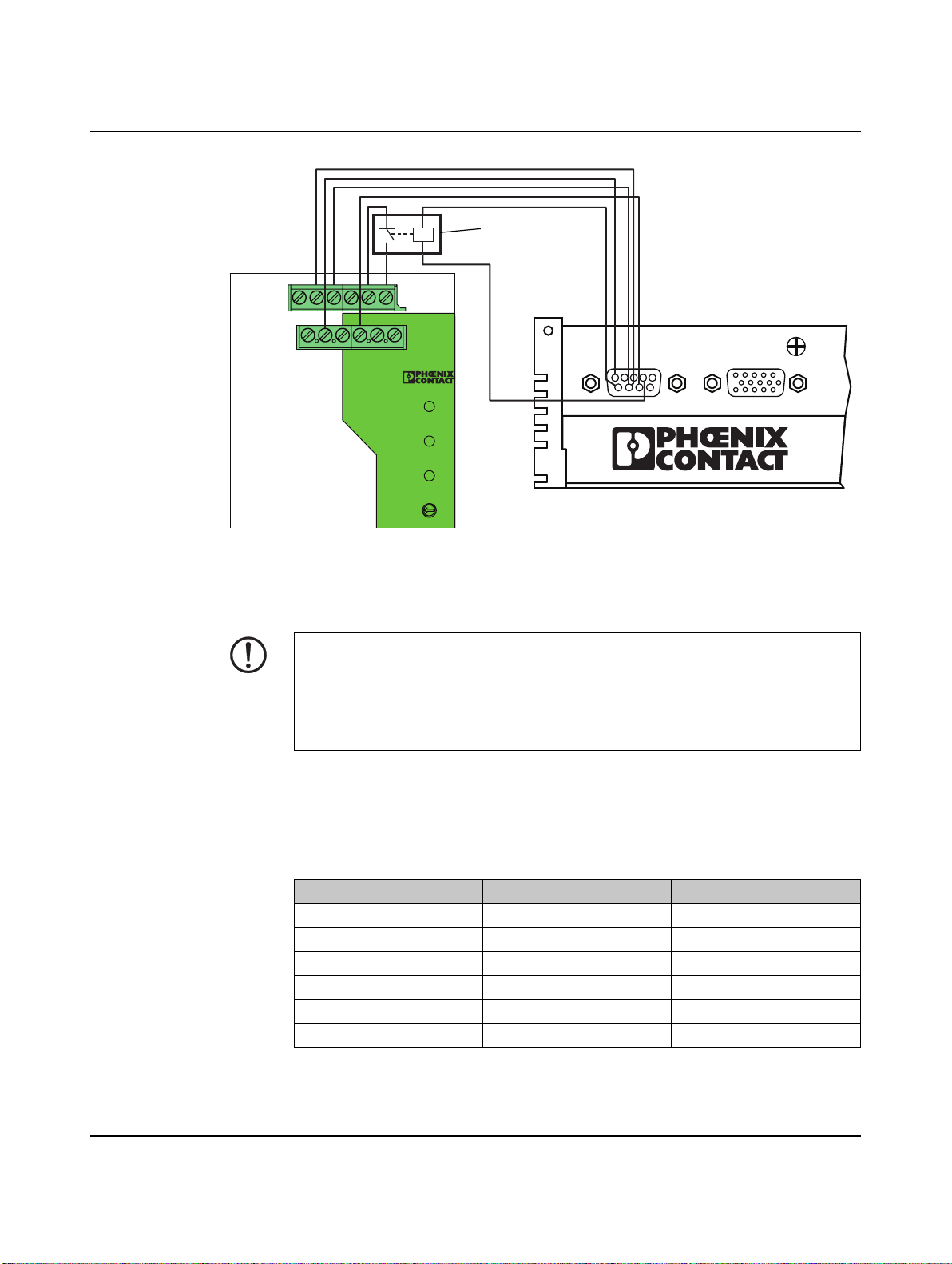
3.8.2 QUINT-DC-UPS… installation
When using the QUINT-DC-UPS… uninterruptable power supply, there are two ways to
connect it to the Valueline IPC depending upon the level of monitoring/control desired.
– Power connector: This connection method allows monitoring of the Bat.-Mode signal
via two terminals labeled A and B on the power connector. When the uninterruptable
power supply switches to battery power, it closes a contact to activate the Bat.-Mode
signal. The operating system starts the “Minutes on battery before critical alarm” timer,
if it is configured by the user (see Figure 3-39). If it is not configured, the operating
system starts the Critical Alarm timer which gives 30 seconds to launch and execute an
optional program before the VL IPC initiates the shutdown procedure.
Any program launched at this time is typically used to send an alert message to a system
administrator that the computer is shutting down. This program must reside in
C:\Windows\system32.
– Serial port (DB-9): This connection method provides additional communication
between the Valueline IPC and the uninterruptable power supply.
– As in the power connection method, when the un interruptible power supply
switches to battery power, it closes a contact to activate the Bat.-Mode signal. The
operating system starts the “Minutes on battery before critical alarm” timer, if it is
configured by the user (see Figure 3-39). If it is not configured, the operating
system starts the Critical Alarm timer which gives 30 seconds to launch and
execute an optional program before the VL IPC initiates the shutdown procedure.
2637_en_D PHOENIX CONTACT 3-31

Valueline IPC
– Monitors the state of the Low Battery Alarm, which is a contact closure inside the
UPS, after the battery reaches approximately 20.4 V. When this signal is active, the
Windows operating system starts the Critical Alarm timer which gives 30 seconds
to launch and execute an optional program before the VL IPC begins the shutdown
procedure.
– Shuts down the UPS: When the VL IPC turns off, it can also turn off the UPS
through an external dry contact while the UPS is in Battery Mode. The dry contact
buffers the UPS inputs from the VL IPC’s 9.5 V DC while it is powered-on.
CAUTION:
Disconnect power before installing un interruptible power supply.
1. Connect the wires in the desired method.
X1: PWR 24VDC
X2 ETH
+– AB
+24V 11 21 31 R1 R2
12 13 22233233
Figure 3-34 Power connector A and B
PHOENIX CONTACT 2637_en_D
3-32
+24V 11 21 31 R1 R2
Startup and Operation
Relay
12 13 22233233
2
4
1
5
3
6
87
9
X10 COM1 X9 VGA
Figure 3-35 DB-9 serial port connection
For the serial port connection, a female DB-9 connector must be obtained. Also, a relay
must be obtained and incorporated into the connections. Table 3-3 also shows the wire
connections.
NOTE:
The Valueline IPC serial port and pins A-B on the power connector cannot accept 24 V.
The un interruptible power supply shutdown must be initiated through dry contacts. The
QUINT-DC-UPS… must be configured for dry contact mode. If another type of un
interruptible power supply is used, it must be configured for dry contact mode or a relay
must be installed between the Valueline IPC and the uninterruptable power supply.
For either type of connection, place the QUINT-DC-UPS… in dry contact mode.
– Remove the 24 V DC jumper from terminal 21. This is the Bat.-Mode output.
– Remove the 24 V DC jumper from terminal 11. This is the alarm output.
– Remove the 24 V DC jumper from R1 and R2. This is the UPS shutdown input.
Table 3-3 QUINT-DC-UPS… connections
QUINT DC-UPS… VL IPC Power Connector VL IPC DB-9 Connector
21 - Bat. Mode A 7
23 - Bat. Mode B 8
11 - Alarm 7
13 - Alarm 1
R1 - Relay 4
R2 - Relay 6
1
Not a direct connection. Relay must be installed in circuit (see “DB-9 serial port
1
1
connection” ).
2637_en_D PHOENIX CONTACT 3-33

Valueline IPC
2. In the Windows XP Control Panel, double-click the “Power Options” icon and click the
“UPS” tab (not available in Windows 7).
Figure 3-36 “UPS Selection” dialog box
3. Click the “Select” button and set these options:
– In the “Select manufacturer” field, select Generic from the drop-down menu.
– In the “Select model” field, select Custom.
– In the “On port” field, select either COM1 for the DB-9 connector or COM2 for the power
connector (pins A-B).
Click the “Next” button to proceed to the next screen.
Figure 3-37 “UPS Interface Configuration” dialog box
4. Click the “Power Fail/On Battery” check box and click the “Positive” radio button.
5. Click the “Low Battery” and “UPS Shutdown” check boxes if those functions are
connected using the DB-9 serial port connector. Do not click these check boxes if the
power connector method is used.
PHOENIX CONTACT 2637_en_D
3-34

Startup and Operation
6. Click the “Finish” button to return to the “Power Options Properties… UPS” dialog box.
Figure 3-38 “Power Options Properties” dialog box
7. Click the “Configure” button.
8. The suggested configuration of the driver is as follows:
– Click the “Enable all notifications” check box to display a message when the VL IPC
goes to battery power.
– Set the number of seconds before the first message displays to 5 seconds. This
prevents false alarms if the power supply drops out of the operating range for a short
time.
2637_en_D PHOENIX CONTACT 3-35

Valueline IPC
– Set the desired number of seconds before subsequent messages are displayed.
Figure 3-39 “UPS Configuration” dialog box
– Click the “Minutes on battery before critical alarm” check box and set the amount of time
for the IPC to be on battery power once the UPS is in that mode (increased battery
power will allow longer time settings). When the time expires, the operating system
initiates a 30 second critical alarm timer and then begins the shutdown process.
If pins 11 and 13 are connected through the DB-9 connector to monitor a low battery, the
low battery alarm may override the number of minutes the VL IPC will operate before
creating a critical alarm.
9. If desired, click the “When the alarm occurs, run this program” check box and enter the
program file in the field. When using this feature:
– The command file must reside in C:\Windows\system32 and have a file extension of
.exe, .com, .bat or .cmd.
– Administrative privileges may be required.
– Command files that initiate a dialog box and require user input cannot be used.
– The command file must finish running within 30 seconds or it may impede the shutdown
process.
– If desired, click the “Finally, turn off the UPS” check box to turn the uninterruptable
power supply off after a shutdown. This will prevent the battery from a complete
drawdown and result in longer battery life.
10. Click the “OK” button to return to the “Power Options Properties… UPS” dialog box.
11. Click the “Apply” button to save the configuration. When saved, click the “OK” button to
close the dialog box.
PHOENIX CONTACT 2637_en_D
3-36

UPS-CONF
Startup and Operation
3.8.3 TRIO-UPS… installation
1. Connect the TRIO-UPS… to a USB port on the VL IPC using the IFS-USB-PROGADAPTER (Order No. 2811271) data cable.
2. Apply power to the VL IPC and wait for the boot-up process to complete.
3. If prompted by the operating system, install the updated driver for the IFS-USB-PROGADAPTER from the internet.
A CD with the UPS-CONF software is shipped with the TRIO-UPS… It is also available at
www.phoenixcontact.com.
4. Install the UPS-CONF software.
5. Double-click the icon in the notification area to open the UPS-CONF interface.
6. The software should be communicating with the TRIO-UPS… and displaying the
current operating status at the bottom of the interface.
7. Set the buffer time setting switch to PC-MODE to establish the shutdown behavior
through the UPS-CONF software. The switch position is also shown in the Operation
Mode area of the UPS-CONF user interface.
Figure 3-40 UPS-CONF interface and TRIO buffer time setting switch
8. Set the TRIO-UPS… as desired according to the user manual.
Switch
2637_en_D PHOENIX CONTACT 3-37

Valueline IPC
3.9 Accessing the optical drive
Use the optional CD-RW/DVD-RW to install programs or backup control programs and
data. To insert or remove a CD/DVD, follow these steps:
1. Open the access door.
2. Press the eject button to remove an optical disk.
Optical Drive
Eject Button
1 3
X10 COM1 X9 VGA
6
2
87
4
9
5
ERROR
X8 DVI D
RUN
HDD PWR
X7 USB
X5 USB
X4 USBX6 USB
Figure 3-41 Optical drive eject button
3. Insert the CD/DVD in the proper orientation for the drive. The recorded/recordable side
should face down or left.
4. Gently push the CD/DVD disk in the slot.
PHOENIX CONTACT 2637_en_D
3-38

Startup and Operation
H
3.10 Using CompactFlash cards
Valueline IPC CompactFlash® slots are not hot-swappable. The eject button is only to be
used once the Valueline IPC is powered-down for ease of CompactFlash card
exchangeability.
To install a CompactFlash card follow these steps:
NOTE:
CompactFlash cards are handled like hard drives in a Valueline IPC and are, therefore, not
hot-swappable. Ejecting a CompactFlash before the VL IPC is powered-down could result
in data loss.
1. Turn the VL IPC off.
2. Open the access door at the rear of the VL IPC (see Figure 3-42).
Core2 Duo and
Celeron Processor
1 3
X10 COM1 X9 VGA
6
2
87
4
9
5
Atom Processor
CompactFlash
Slot 0
CompactFlash
Slot 1
Eject Button
X8 DVI D
CompactFlash
Slot 1
X4 USBX6 USB
X3 ETH X2 ET
Figure 3-42 CompactFlash slots
ERROR
RUN
HDD PWR
X7 USB
X5 USB
CompactFlash
Eject Button
CompactFlash
Slot 1
X9 COM
X8 VGA
X4 USBX6 USB
X3 ETH X2 ET
1
6
2
3
87
4
9
5
ERROR
RUN
HDD PWR
X7 USB
X5 USB
You may need to remove some cables for easier access to the CompactFlash slots.
2637_en_D PHOENIX CONTACT 3-39

Valueline IPC
3. Install a CompactFlash card in the proper slot. The card should be inserted so the lip is
toward the connectors. Push the card straight into the device until seated.
When inserting a CompactFlash card, use the slot 0 for bootable CompactFlash cards and
the slot 1 for data-only CompactFlash cards.
4. To select a bootable CompactFlash, the BIOS must be properly configured (see “BIOS
configuration” on page 4-6).
To remove a card from slot 0, use a small needle nose pliers and carefully pull the card
straight out. To remove a card from slot 1, use the ejector mechanism. Push the button next
to the slot, and then pull the card straight out of the slot.
PHOENIX CONTACT 2637_en_D
3-40

4 Maintenance
Maintenance
The Valueline IPC has several removable components.
To access some of these components, it may be necessary to remove cables connected
to the VL IPC.
2637_en_D PHOENIX CONTACT 4-1

Valueline IPC
4.1 VL IPC components
There is an access door under the connectors of the VL IPC system module (see
Figure 4-1). Under the access door are two type II CompactFlash® slots (slot 0 and slot 1),
a bay for an optional optical storage device, a removable hard disk bay, and the RTC
battery.
Serial Port
CompactFlash
Slot 0
Optional
Optical Storage Device
VGA Video
CompactFlash
Slot 1
DVI-D
USB Ports (4)
Ethernet Ports
X10 COM1 X9 VGA
X8 DVI D
X4 USBX6 USB
X3 ETH X2 ETH
1
2
3
876
4
9
5
PCI Slot 1
ERROR RUN HDD PWR
Status LEDs
X7 USB
X5 USB
PCI Slot 0
Removable
Hard Disk
RTC Battery
24 V DC
X1: PWR 24VDC
+– AB
Power Switch
(entire back)
Power Connector
Figure 4-1 VL IPC with access door open
PHOENIX CONTACT 2637_en_D
4-2
Heat Sink

CompactFlash
Slot 0
X9 COM
6
87
9
13
2
4
5
Maintenance
Serial Port
CompactFlash
Slot 1
VGA Video
USB Ports (4)
Ethernet Ports
Removable
Hard Disk
RTC Battery
24 V DC
Power Connector
X8 VGA
X4 USBX6 USB
X3 ETH X2 ETH
+– AB
X1: PWR 24VDC
ERROR
RUN
HDD PWR
X7 USB
X5 USB
Status LEDs
Power Switch
Heat Sink
(entire back)
Figure 4-2 VL IPC with Atom processor in Atom enhanced chassis with access door
open
2637_en_D PHOENIX CONTACT 4-3

Valueline IPC
Serial Port
CompactFlash
Slot 1
X9 COM
X8 VGA
13
6
2
87
4
9
5
ERROR
RUN
HDD PWR
Status LEDs
VGA Video
X7 USB
USB Ports (4)
X4 USBX6 USB
X3 ETH X2 ETH
X5 USB
Ethernet Ports
RTC Battery
24 V DC
Power Connector
X1: PWR 24VDC
Power Switch
+– AB
Heat Sink
(entire back)
Figure 4-3 VL IPC with Atom processor in Atom standard chassis with access door
open
PHOENIX CONTACT 2637_en_D
4-4

Maintenance
X
3
E
T
H
X
2
E
TH
POWER: 24 VDC
+
–
A
B
4.1.1 Real-time clock battery
There is a battery located under the access door. This battery supplies power to the RealTime Clock (RTC) in the VL IPC when the system is not connected to a 24 V DC power
source. The battery has a typical life of 5 years and requires replacement occasionally.
To replace the battery
1. Open the access door at the rear of the IPC module.
2. The RTC battery is above the hard disk slot. Use a needle nose pliers to carefully pull
out the battery.
3. Be sure to replace the battery with the same type (CR2032 3V Lithium), oriented as
shown in Figure 4-4.
—
CR2032 3V Lithium battery
Positive (+)
Figure 4-4 Insert RTC battery as shown
4.1.2 Hard disk drive
The hard drive installs in a tray that is easily removable. VL IPC systems without a hard drive
come with a blank tray. To install a new hard drive or replace the current hard drive, follow
these instructions:
1. Remove power from the unit.
If necessary, move or disconnect any cables that interfere with accessing the hard drive.
2. Open the access door.
3. Turn the screw counterclockwise several turns. It is spring-loaded and, when it clears
the threads, it pops out.
4. Grasp the screw and swing the front lever out from the door.
2637_en_D PHOENIX CONTACT 4-5

Valueline IPC
5. Pull the lever to slide the tray and hard drive assembly out of the bay.
Hold the access door flat to ensure the tray clears as it is removed.
6. If present, the hard drive can be removed from the tray by removing the four screws
along the sides of the hard drive.
7. If necessary, install the hard drive in a tray using the appropriate mounting hardware for
the drive.
The VL IPC can be operated without a hard drive (booted from the CompactFlash Master).
For extended operating periods, it is recommended that an empty tray be installed in the
drive bay and locked closed.
8. With the hard drive installed in the tray (or with a blank tray), orient the tray so the front
lever is fully extended and toward the power connector. Slide the assembly straight into
the slot until it clicks into place.
9. Gently push the drive in so the connector is properly seated.
10. Swing the front lever flat across the front of the drive assembly.
11. Using a screwdriver, push the screw in and turn clockwise to secure the front lever.
12. Close the access door and return any removed cables to their proper connector.
13. Restore power.
4.2 BIOS configuration
Although Phoenix Contact doesn’t recommend changing BIOS configuration settings
without specific instruction from Phoenix Contact Technical Services, this is something that
may be necessary. To access the BIOS configuration, there must be an attached (physical)
keyboard through one of the USB ports. During boot-up, the BIOS briefly displays the
comment “Press DEL to enter Setup.” Follow the on-screen instructions and be sure to save
any changes.
4.2.1 Boot options
There are two boot modes in the VL IPC.
Automatic boot mode
Automatic mode checks for bootable devices in the order (first, second and third) specified
in the BIOS. To view or change a boot device:
1. Power-up or restart the VL IPC and, when the first black screen with white text appears,
press the <Delete> key about once every second to initiate the BIOS Setup Utility.
2. Use the arrow keys to highlight Advanced BIOS Features then press the <Enter> key.
PHOENIX CONTACT 2637_en_D
4-6

Maintenance
3. Select a device boot order (first, second or third) then press the <Enter> key.
a) Select a device:
Hard Disk CDROM
USB-FDD PXE Boot X3:ETH
PXE Boot X2:ETH Disabled
If a bootable CompactFlash card is installed, CF Slot 0 and/or CF Slot 1 will appear as
selections.
Additional items will be listed if an expansion chassis is installed with one or two
network cards that support network booting.
b) Press the <Enter> key to accept the device or press the <Esc> key to abort the
change.
4. Boot Other Device looks for any bootable device in case the first, second and third
boot devices fail or are not available. To enable this feature:
a) Use the arrow keys to highlight Boot Other Device and press the <Enter> key.
b) Select Enabled then press the <Enter> key to accept the change.
5. When more than one hard disk device type or CDROM device type is connected to the
VL IPC, they can be prioritized in the boot order. To do that:
a) From the Advanced BIOS Features menu, select either Hard Disk Boot Priority
or CD-ROM Boot Priority using the arrow keys.
b) Follow the Item Help directions on the right side to move (prioritize) a highlighted
device up or down in the list.
c) Press the <Esc> key to save the change and exit the submenu.
6. When ready, press the <F10> key to save changes, exit and continue booting the VL
IPC.
Manual boot mode
Manual boot mode overrides automatic boot mode and allows users to boot from external
USB devices such as a memory stick, CompactFlash card, CD-ROM, etc. To boot from an
external device:
1. Connect a bootable USB device before booting. Otherwise, it will not be listed in the
Boot menu.
2. Power-up or restart the VL IPC and, when the first black screen with white text appears,
press the <F12> key about once every second to initiate the Boot menu.
3. Use the arrow keys to highlight the desired device under Hard Disk or CDROM, then
press the <Enter> key to boot from that device.
4.2.2 Power on after power fail options
The Valueline IPC provides three options for power-up behavior once power is applied. To
change the setting:
1. Select Integrated Peripherals.
2. Select SuperIO Device.
3. Select PWRON After PWR-Fail.
4. Select:
a) OFF - for the VL IPC to remain OFF.
b) ON - for the VL IPC to power-up and reboot when power is restored (the default
mode).
2637_en_D PHOENIX CONTACT 4-7

Valueline IPC
c) Former-Sts - for the VL IPC to maintain it’s on or off status before power was
restored.
5. Press the <Enter> key to accept the change.
6. Save the change and confirm it.
4.3 Troubleshooting
4.3.1 Video driver
The Intel Graphics Media Driver user interfaces are inaccessible
If you cannot access an interface through a right-click on the desktop (see “User interface”
on page 3-18) or through the notification area icon, try the following:
– Right-click on the desktop, click the “Properties” tab, click the “Advanced” button, click
the “Troubleshoot” tab and make sure the “Hardware Acceleration” slider is set to full.
Click the “Apply” button, and then the “OK” button. Reboot the system. From the rightclick menu, Graphics Properties (displays the Intel GMA User Interface) and
Graphics Options (certain tools from the Intel GMA UI) are available as options.
– Reload the video driver. Go to C:\Phoenix Contact\ValueLine IPC\Drivers\Video,
launch Setup and respond to the prompts accordingly.
Reloading the driver will overwrite any saved graphics settings (rotate, screen resolutions,
color balances, etc.).
4.3.2 QUINT-DC-UPS… and Valueline IPC (Windows XP)
VL IPC starts, displays the desktop, and then turns off.
– If the UPS is in battery mode, then this is a normal action as controlled by the
operating system’s generic UPS driver to conserve battery power.
– (short time to do this): Before boot-up completes click “Start… Control Panel…
Power Options… UPS” tab and then click the “Select… Custom… Next” button.
Make sure the “Negative” radio button is not selected for any signal (whether or not
the signal is used).
UPS doesn’t supply 24 V DC during battery mode.
– Check the battery fuse(s) to make sure they are not blown.
– Check the connections between the battery and the UPS.
VL IPC doesn’t start. Make sure
– 24 V DC lines are properly connected from the UPS to the VL IPC.
– AC power is supplied to the UPS.
– UPS is outputting 24 V DC.
UPS configurations are not working properly:
– Make sure the QUINT-DC-UPS… is properly configured for dry contact operation.
– Disconnect the status lines between the UPS and VL IPC and check if they are
wired (see Figure 3-35). Use an ohmmeter to test each line for 0 Ω resistance
between both ends. When that is true, reconnect the status lines between the UPS
and VL IPC.
– Make sure the UPS is running in normal mode (not on battery).
PHOENIX CONTACT 2637_en_D
4-8

Maintenance
– Make sure the VL IPC is running and disconnected from any hardware other than
UPS power and status lines.
– Remove the operating system generic UPS driver configuration: from the VL IPC
click the “Start… Control Panel… Power Options… UPS” tab, click the “Select”
button and choose None as the manufacturer. Click the “Finish” button and then
the “Apply” button (not the “OK” button).
– Reconfigure the operating system generic UPS driver (see “QUINT-DC-UPS…
installation” on page 3-31). Once the “Apply” button is selected, the system will
take approximately 25 seconds to update.
Figure 4-5 “Power Options Properties” dialog box
– The VL IPC reads the state of the Bat.-mode signal through the configured serial
port. If everything is connected, configured and operating correctly, then AC power
is displayed as the current power source.
– Make sure the UPS battery is charged (Bat.-Charge LED on the QUINT-DC-UPS…
is off).
– Remove power from the UPS, which changes the state of the Bat.-mode signal to
display On Battery as the current power source. Make sure the VL IPC shuts down
30 seconds after the configured time has expired.
– Reconnect pertinent UPS and VL IPC hardware and reconnect the UPS to the
power supply.
4.3.3 Miscellaneous solutions
What is the correct type of CompactFlash memory?
– Industrial fixed media CompactFlash cards must be used in the Valueline IPC
CompactFlash slots. Though the brand does not matter, the type of card does.
Therefore, as the Windows® operating system will not boot from consumer grade
removable media CompactFlash cards in a Valueline IPC, they cannot be used.
Is the CompactFlash memory hot-swappable?
– Never hot-swap CompactFlash cards as they are considered as hard drives in a
Valueline IPC. Therefore, hot-swapping CompactFlash cards in a Valueline IPC
could lead to data loss or a corrupted CompactFlash card.
Valueline IPC will not start an operating system from a USB port.
– Contact technical support.
2637_en_D PHOENIX CONTACT 4-9

Valueline IPC
PHOENIX CONTACT 2637_en_D
4-10

A Product data
A 1 Ordering data
Products
Description Type Order No. Pcs./Pkt.
Industrial PC, configurable Valueline IPC 2913108
a. An order key must be appended to the 7-digit order number to reflect the various options that are specified in each configuration. The order key is
generated using the Phoenix Contact on-line configuration tool.
Accessories
Description Type Order No. Pcs./Pkt.
Power supply unit, primary switched-mode TRIO-PS/1AC/24DC/2.5 2866268 1
Power supply unit, primary switched-mode TRIO-PS/1AC/24DC/5 2866310 1
Power supply unit, primary switched-mode TRIO-PS/1AC/24DC/10 2866323 1
Power supply unit, primary switched-mode QUINT-PS/1AC/24DC/3.5 2866747 1
Power supply unit, primary switched-mode QUINT-PS/1AC/24DC/5 2866750 1
Power supply unit, primary switched-mode QUINT-PS/1AC/24DC/10 2866763 1
Mounting kit, panel installation, replacement VL PANEL MOUNTING KIT 2913159 1
Mounting kit, bookshelf installation, replacement VL BOOKSHELF MOUNTING KIT 2913160 1
Mounting kit, bookshelf with PCI slots installation, replacement VL BOOKSHELF MOUNTING KIT/
EXPANSION
HDD tray kit, removable HDD TRAY KIT 2913185 1
a
2913164 1
1
A 2 Technical data
General data
Dimensions (width x height x depth)
VL IPC without PCI slots, no display
VL IPC with PCI slots, no display
Display only, 12 in.
Display only, 15 in.
Display only, 17 in.
Display only, 19 in.
Display only, 24 in.
Ambient temperature (operating)
– with no display, 12-, 15- or 17-in. display and solid state drive or
CompactFlash card
– with no display, 12-, 15- or 17-in. display and rotating hard drive
– with 19- or 24-in. display and solid state drive or CompactFlash card
and rotating hard drive
– with 19- or 24-in. display and rotating hard drive
Ambient temperature (storage/transport) -40 … 70°C
Permissible humidity (relative) 5 … 95%
Weight
without PCI slots
with PCI slots
Display, 12 in.
Display, 15 in.
Display, 17 in.
Display, 19 in.
Display, 24 in.
265 x 207x 49 mm
265 x 207 x 87 mm
365 x 282 x 45 mm
410 x 309 x 47 mm
452 x 356.5 x 50 mm
489 x 406 x 48 mm
670 x 404 x 49 mm
-20… 55°C
5… 55°C
0… 50°C
5… 50°C
3.40 kg
5.35 kg
4.46 kg
4.51 kg
6.43 kg
9.51 kg
12.47 kg
2637_en_D PHOENIX CONTACT A-1

Valueline IPC
General data (continued)
Degree of protection IP65 (front), IP20 (back)
UL Type 4
Mounting Panel, bookshelf, and wall
LED indicators Power, HDD, Run, Error
a. Only 12-, 15- and 17-in. displays without the front USB port
a
Electrical data
Power supply, nominal 24 V DC
Power supply, range 19.2 - 28.8 V DC
Power supply connector Removable Combicon screw-type
Conductor size 0.2… 2.5 mm² (24… 12 AWG)
Torque 5… 6 Nm
RTC battery, typical life 5 years
Recommended power supply size
Atom™ processor with no display, 12-in, 15-in. display 2.5 A
All other processors 5.0 A
Any configuration with PCI slots 5.0 A
Computer data
Operating system (configurable option) Windows® XP
Processor (configurable option) 1.60 GHz Intel® Atom™ N270, 533FSB, 512 kB L2 Cache
RAM (configurable option) 1 GB… 3 GB
Data memory (configurable option) 2.5 in. SATA hard drive
Optical drive (configurable option) CD-RW/DVD-RW
Number of CompactFlash® slots 2 maximum
Number of PCI slots (configurable option) 2 maximum
PCI card size (maximum)
Slot 1 (see page 1-2)
Slot 0 (see page 1-2)
Maximum current draw per PCI slot 600 mA
Windows 7
Windows Embedded Standard 2009 (XP)
Windows Embedded Standard 7
®
1.06 GHz Intel Celeron
1.5 GHz Intel Core™2 Duo, 667FSB, 4 MB L2 Cache
2.5 in. SATA solid state drive
CompactFlash
169.8 x 106.3 mm
180.9 x 107.9 mm
M, 533FSB, 1 MB L2 Cache
®
Interfaces
USB Type A, USB 1.1/2.0
Number of USB ports 4/5
Serial, RS-232 DB-9, male
Video VGA (DB-15, female)
NVRAM connection Mini-PCI (on-board)
NVRAM size (configurable option) 128 kB
Number of Ethernet connectors 2
Ethernet connection 10/100/1000 Mbps
a. not available with Atom CPU processor
PHOENIX CONTACT 2637_en_D
A-2
DVI-D
a

Display - 24 in.
Screen size, diagonal 608 mm (24.0 in.)
Screen size, horizontal x vertical 531 x 299 mm
Resolution 1920 x 1080
Type Resistive touch screen with serial/USB interface
Brightness 300 Cd/m²
Number of colors 16.7 million
Contrast ratio 1000:1
View angle, horizontal/vertical (CR=10) 170°/180°
Installation cutout dimensions (width x height) 620.4 x 352.8 mm
Outside bezel dimensions (width x height x depth) 670.0 x 404.0 x 10 mm
Backlight life, minimum 50000 hr.
Interface USB 1.1/2.0, Type A
Display - 19 in.
Screen size, diagonal 483 mm (19.0 in.)
Screen size, horizontal x vertical 376 x 301 mm
Resolution 1280 x 1024
Type Resistive touch screen with serial/USB interface
Brightness 300 Cd/m²
Number of colors 16.7 million
Contrast ratio 1300:1
View angle, horizontal/vertical (CR=10) 89°/89°
Installation cutout dimensions (width x height) 443 x 360 mm
Outside bezel dimensions (width x height x depth) 488.6 x 406.0 x 10 mm
Backlight life, minimum 50000 hr.
Interface USB 1.1/2.0, Type A
Technical data
Display - 17 in.
Screen size, diagonal 430 mm (16.93 in.)
Screen size, horizontal x vertical 338 x 270 mm
Resolution 1280 x 1024
Type Resistive touch screen with serial/USB interface
Brightness 350 Cd/m²
Number of colors 16.7 million
Contrast ratio 1000:1
View angle, horizontal/vertical (CR=10) 85°/80°
Installation cutout dimensions (width x height) 424.0 x 329.5 mm
Outside bezel dimensions (width x height x depth) 452.0 x 356.5 x 10 mm
Backlight life, minimum 50000 hr.
Interface (configurable option) USB 1.1/2.0, Type A
2637_en_D PHOENIX CONTACT A-3

Valueline IPC
Display - 15 in.
Screen size, diagonal 378 mm (14.88 in.)
Screen size, horizontal x vertical 304 x 228 mm
Resolution 1024 x 768
Type Resistive touch screen with serial/USB interface
Brightness 350 Cd/m²
Number of colors 16.2 million
Contrast ratio 700:1
View angle, horizontal/vertical (CR=10) 70°/65°
Installation cutout dimensions (width x height) 386.6 x 285.0 mm
Outside bezel dimensions (width x height x depth) 410 x 309 x 10 mm
Backlight life, minimum 50000 hr.
Interface (configurable option) USB 1.1/2.0, Type A
Display - 12 in.
Screen size, diagonal 307 mm (12.1 in.)
Screen size, horizontal x vertical 246 x 185 mm
Resolution 800 x 600
Type Resistive touch screen with serial/USB interface
Brightness 400 Cd/m²
Number of colors 16.2 million
Contrast ratio 600:1
View angle, horizontal/vertical (CR=10) 70°/60°
Installation cutout dimensions (width x height) 334.0 x 253.0 mm
Outside bezel dimensions (width x height x depth) 365 x 282 x 10 mm
Backlight life, minimum 50000 hr.
Interface (configurable option) USB 1.1/2.0, Type A
Mechanical tests
Shock test according to IEC 60068-2-27 15g, 11 ms impulse
Vibration resistance according to IEC 61131-2 Hard Drive: 0.5 g
CompactFlash: 1.0g
Conformance with EMC Directives
Developed according to IEC 61000-6-2
IEC 61000-4-2 (ESD) Criterion B
IEC 61000-4-3 (radiated-noise immunity) Criterion A
IEC 61000-4-4 (burst) Criterion B
IEC 61000-4-5 (surge) Criterion B
IEC 61000-4-6 (conducted noise immunity) Criterion A
IEC 61000-4-8 (noise immunity against magnetic fields) Criterion A
EN 55022 (noise emission) Class A
Approvals
Conformity c
Listing U UL 508
Hazardous location U Class I, Division 2, Groups A, B, C, D
a. Displays with front USB ports do not qualify with Class I, Division 2 listing
a
PHOENIX CONTACT 2637_en_D
A-4

B Appendices
Section 1
Section 2
B 1 List of figures
Figure 1-1: Valueline IPC with Core™2 Duo or Celeron® processor and
optional PCI slots ...............................................................................1-2
Figure 1-2: VL IPC with Atom processor in Atom enhanced chassis ....................1-3
Figure 1-3: VL IPC with Atom processor in Atom standard chassis ......................1-4
Figure 1-4: LED layout .........................................................................................1-5
Figure 2-1: Wall and bookshelf mounts ................................................................2-2
Figure 2-2: Panel mount .......................................................................................2-3
Figure 2-3: Panel cut-out dimensions for displays ................................................2-4
Figure 2-4: Panel mount clamps ..........................................................................2-5
Figure 2-5: Interface connections .........................................................................2-6
Figure 2-6: Cover removal ....................................................................................2-8
Figure 2-7: Side panel and bracket removal .........................................................2-9
Figure 2-8: PCI slot 0 removal ............................................................................2-10
Figure 2-9: PCI slot 0 card installation ................................................................2-11
Section 3
Figure 3-1: VL IPC power connection ...................................................................3-1
Figure 3-2: Power switch ......................................................................................3-2
Figure 3-3: “Touchkit… Setting” dialog box ..........................................................3-4
Figure 3-4: Mouse mode “Option” dialog box .......................................................3-6
Figure 3-5: “Touchkit… Tools” dialog box ............................................................3-7
Figure 3-6: 4 Points Calibration screen ................................................................3-8
Figure 3-7: 9 Points Calibration screen ................................................................3-9
Figure 3-8: Draw Test screen .............................................................................3-10
Figure 3-9: “Touchkit… Edge Compensation” dialog box ...................................3-11
Figure 3-10: Edge compensation example ...........................................................3-12
Figure 3-11: “Touchkit… Hardware” dialog box ...................................................3-13
Figure 3-12: “Saturn - Hardware Configuration” dialog box ..................................3-13
2637_en_D PHOENIX CONTACT B-1

Valueline IPC
Figure 3-13: Touchkit menu .................................................................................3-14
Figure 3-14: The “Brightness Control” window .....................................................3-16
Figure 3-15: Right-Click tool .................................................................................3-16
Figure 3-16: The “On-Screen Keyboard” dialog box ............................................3-17
Figure 3-17: The “On-Screen Keyboard” window (Windows XP) .........................3-17
Figure 3-18: Graphic Media Accelerator direct select options ..............................3-18
Figure 3-19: Graphics Media Accelerator main user interface screen ..................3-19
Figure 3-20: Single digital display selected ..........................................................3-20
Figure 3-21: Display settings for a single display .................................................3-21
Figure 3-22: Color corrections ..............................................................................3-22
Figure 3-23: Extended Desktop selected for multiple displays .............................3-23
Figure 3-24: Display settings for one display of a multiple display setup ..............3-24
Figure 3-25: Color corrections ..............................................................................3-25
Figure 3-26: “OpenGL Settings” dialog box ..........................................................3-25
Figure 3-27: “Overlay Settings” dialog box ...........................................................3-26
Figure 3-28: “Scheme Options” dialog box ...........................................................3-26
Figure 3-29: Modification of hot key shortcuts ....................................................3-27
Figure 3-30: Hot key selection .............................................................................3-28
Figure 3-31: Zoom utility ......................................................................................3-28
Figure 3-32: “Information” dialog boxes ...............................................................3-29
Figure 3-33: Generic 24 V DC function diagram ..................................................3-30
Figure 3-34: Power connector A and B ................................................................3-32
Figure 3-35: DB-9 serial port connection ..............................................................3-33
Figure 3-36: “UPS Selection” dialog box ..............................................................3-34
Figure 3-37: “UPS Interface Configuration” dialog box .........................................3-34
Figure 3-38: “Power Options Properties” dialog box ............................................3-35
Figure 3-39: “UPS Configuration” dialog box ........................................................3-36
Figure 3-40: UPS-CONF interface and TRIO buffer time setting switch ...............3-37
Figure 3-41: Optical drive eject button .................................................................3-38
Figure 3-42: CompactFlash slots .........................................................................3-39
PHOENIX CONTACT 2637_en_D
B-2

Section 4
List of figures
Figure 4-1: VL IPC with access door open ...........................................................4-2
Figure 4-2: VL IPC with Atom processor in Atom enhanced chassis with access
door open ...........................................................................................4-3
Figure 4-3: VL IPC with Atom processor in Atom standard chassis with access
door open ...........................................................................................4-4
Figure 4-4: Insert RTC battery as shown ..............................................................4-5
Figure 4-5: “Power Options Properties” dialog box ..............................................4-9
2637_en_D PHOENIX CONTACT B-3

Valueline IPC
PHOENIX CONTACT 2637_en_D
B-4

Section 1
Section 2
Section 3
B 2 List of tables
Table 1-1: LED status indicators..........................................................................1-5
Table 2-1: Temperature limits..............................................................................2-1
Table 2-2: Cutout dimensions..............................................................................2-4
Table 3-1: Touchkit menu functions...................................................................3-15
Table 3-2: Power requirements..........................................................................3-31
Table 3-3: QUINT-DC-UPS… connections........................................................3-33
2637_en_D PHOENIX CONTACT B-5

Valueline IPC
PHOENIX CONTACT 2637_en_D
B-6
 Loading...