


Stylus Sport 60
Stylus Sport 60Stylus Sport 60
Stylus Sport 60
Almost-Ready-to-Fly
Instruction Manual
Specifications
Wingspan: 70.9 in (1800mm)
Length: 56.2in (1428mm)
Wing Area: 795.1sq in (51.3sq dm)
Flying Weight (GP): 7.28lbs (3300g)
Flying Weight (EP): 6.72lbs (3050g)

www.valuehobby.com/stylus-sport-60.html
- 2 -
Dear Customer,
Congratulations on your purchase of Stylus Sport 60 from Value Hobby. We thank you for your generous support,
and hope you enjoy your new airplane.
At Value Hobby, we hope to offer competitive prices, good performance, and products that you can setup and
use with ease. That’s why we extensively researched and tested this airplane, and suggested all the products
necessary for you to setup properly. We understand that you have many choices when purchasing, and we are
grateful you choose to buy from us.
As vendors, one of the most gratifying things for us is to hear from our customers. We would welcome any
suggestion to help us improve. Please make us aware of any errors and imperfections in the airplane or the
instructions, or about the setup that we suggested. We hope you’ll find our setup suggestions to be helpful, and
enjoy flying your new airplane. Please feel free to contact us at (630) 948-0947 or email us at
support@valuehobby.com
Disclaimer
By purchasing and/or building this model, user assumes ALL liability and risk involved with this product. This
model should be built and flown by an experienced pilot and only flown at AMA sanctioned sites.
Value Hobby guarantees this model to be free of defects in materials and workmanship at the date of purchase.
This warranty does not cover any parts damaged by use or modifications. In no way shall Value Hobby’s liability
exceed the original cost of the purchased model. Further, Value Hobby reserves the right to modify this warranty
without notice. Value Hobby has no control over the final stages of assembly or the material used for the final
assembly. No liability shall be assumed nor materials used for the final user-assembled product. By the act of
using the final product the user accepts all resulting liability. Value Hobby, as a R/C product vendor, provides a
top quality airplane and instructions to complete the model. The quality and flight characteristics of the finished
model depend greatly on how it is built; we cannot guarantee the performance for the completed model and
representations are expressed or implied as to the performance of the completed model. If the buyer is not
prepared to accept the liability associated with the use of this product, the buyer is advised to return this kit
immediately, in new and unused condition.
Safety in Assembly
During assembly of this aircraft, you will be asked to use sharp knives and hobby adhesives. Please follow all
safety procedures recommended by the manufacturers of the products you use, and always follow these
important guidelines:
ALWAYS protect your eyes when working with adhesives, knives, or tools, especially power tools. Safety glasses
are the best way to protect your eyes.
ALWAYS protect your body, especially your hands and fingers when using adhesives, knives, or tools, especially
power tools. Do not cut toward exposed skin with hobby knives. Do not place hobby knives on tables or benches
where they can roll off or be knocked off.
ALWAYS have a first-aid kit handy when working with adhesives, knives, or tools, especially power tools.
ALWAYS keep hobby equipment and supplies out of the reach of children.

www.valuehobby.com/stylus-sport-60.html
- 3 -
Safety in Flying
This is NOT a toy! It is a very high-performance RC airplane capable of high speeds and extreme maneuvers. It
should only be operated by a competent pilot in a safe area with proper supervision.
ONLY fly your aircraft in a safe, open area, away from spectators and vehicles–and where it is legal to fly.
NEVER fly over an unsafe area, such as a road or street.
Never fly too close to yourself or spectators.
Never run your motor inside a house or building with the propeller attached – Remove the prop for safety.
Required Items
CA Glue – Thin and Thick
Epoxy glue
Hobby Knife
Small Phillips Screwdriver
Set Metric Allen Wrenches
Scissors
Small Pliers
Wire Cutters
Masking tape
Optional – Heat gun
Before Starting Assembly
Examination
Unpack your airplane and examine the components. Check for damage of any kind. If you see any damage,
please contact Value Hobby immediately.
Covering
Your airplane was packed in plastic at the factory without any wrinkles in the covering. You may notice some
wrinkles now; more likely, you will notice a few in a day or two or the first time you take the plane out to the
flying field. These wrinkles are the result of wood shrinkage and/or expansion. Balsa wood changes size and
shape slightly as it is exposed to varying humidity in the air. This is a natural property of balsa wood. As your
airplane adjusts to the weather in your part of the world, wrinkles may appear and disappear. Wrinkles may be
removed with the gentle application of heat to the covering material on your airplane. The best tool to use is a
hobby heat gun. Apply the heat gently: the covering material will shrink as you apply the heat, and this will
remove the wrinkles. BE CAREFUL! Too much heat applied too quickly can damage the covering, either by
causing it to pull away from the wood at seams and corners or even by melting it. The covering will shrink at low
temperature with patient application of heat.
Wrinkles in the covering DO NOT affect flight performance.
Remove the canopy before attempting to use heat on your covering! The canopy is made of thermo-activated
plastic and WILL deform with the application of heat. Do not apply heat to the canopy.
If you need to clean your airplane, we recommend using a damp towel. The paint used on the canopy and cowl is
not safe for all cleaners. In particular, DO NOT use alcohol on these parts, it will remove the paint.

www.valuehobby.com/stylus-sport-60.html
- 4 -
Recommended Setup
Main Parts
Configuration Model Qty
Radio 4 channel 1
Motor Size
GForce G46 Brushless Outrunner Motor′600KV)
1
Speed Control 80A Brushless ESC 1
Recommended
Battery′LiPO″
GForce 40C 3300mAh 4S 14.8V LiPO
1
Prop Size 14 X 7 or 15 X 6 1
Servos Standard servos
5 (nitro)
4 (electric)
Y-Harness
Universal Servo Y-Harness ′300mm″11.8-Inch (Futaba "J" and
JR Compatible)
1
Extension
Universal Servo Extension ′600mm″23.6-Inch (Futaba "J" and
JR Compatible)
2
Charger GT POWER X-CHARGER C6 6S LiPO Charger 1
www.valuehobby.com/stylus-sport-60.html
- 5 -
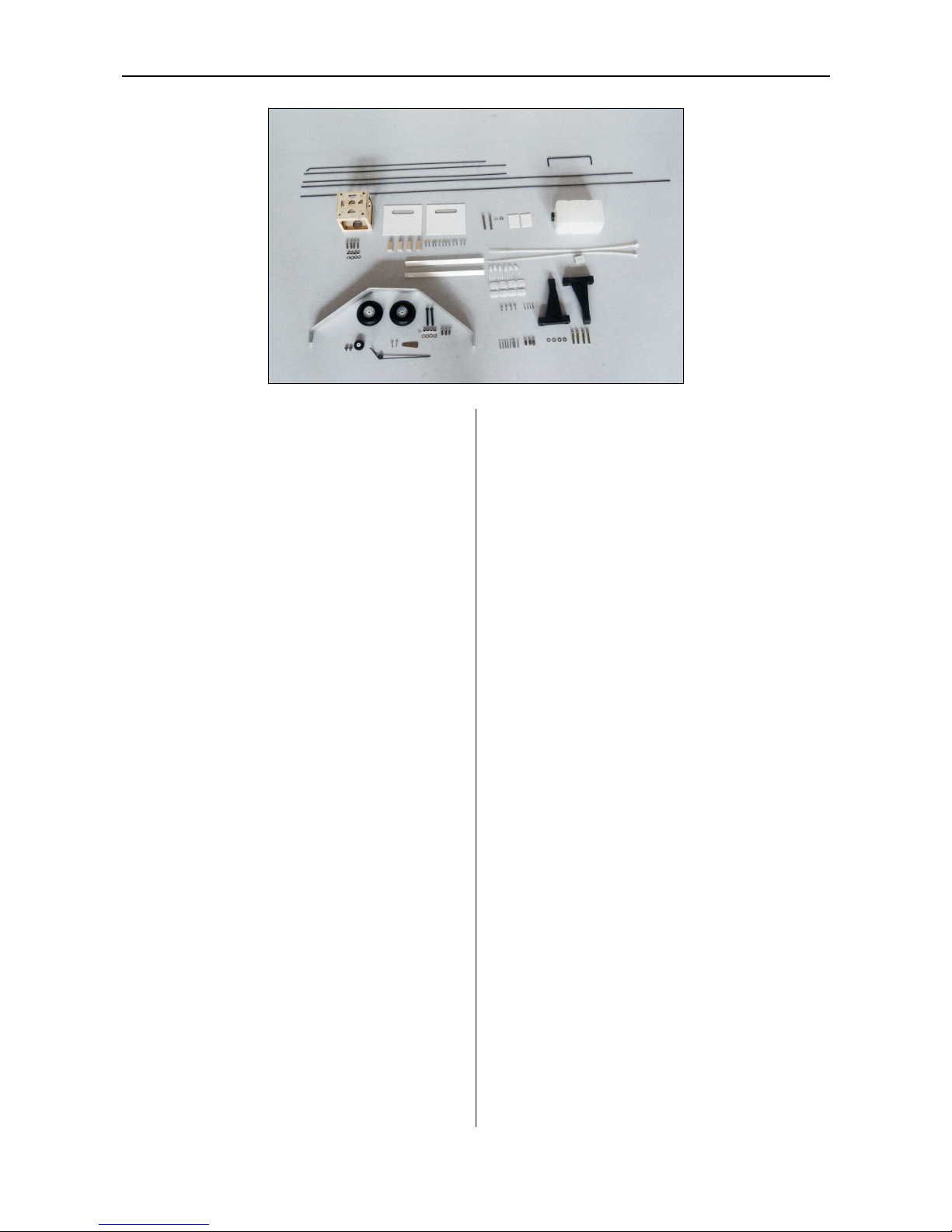
Accessories:
Pack1:
Engine mount-59x80mm (2.3x3.1in) 1 pair
Screw-M3*25mm (1.0in) 4pcs
Washer-Φ4mm (0.16in) 4pcs
Fuel tank assembly-360cc 1pcs
Cable tie-350mm (13.8in) 2pcs
Pack2:
Motor Mount
Socket cap machine screw-M4*16mm (.6in) 4pcs
Nut M4 4pcs
Washer Φ4mm (0.16in) 4pcs
Pack3:
Landing Gear 1pcs
Philips roundhead screw-M4*12mm (.5in) 3pcs
Washer-Φ4mm (.16in) 4pcs
Main wheels-Φ65mm (2.6in) 2pcs
Socket cap machine screw-M4*35mm (1.4in) 2pcs
Locknut-M4 4pcs
Pack4:
Self-tapping screws -M2.5*8mm (.3in) 4pcs
Wing bolt plate 2pcs
Philips roundhead screw-M4*35mm (1.4in) 2pcs
Washer-Φ4 2pcs
Pack5:
Servo hatch 2pcs
Servo mounting block 10x15x20mm (.4x.6x.8in) 4pcs
Self-tapping screw-M2.5*8 mm (.3in) 12pcs
Pack6:
Aileron Servo pushrodΦ1.8*150mm (5.9in) 2pcs
Elevator servo pushrod-Φ1.8*900mm (35.5in) 1pcs
Rudder servo pushrod-Φ1.8*900mm (35.5in) 1pcs
Throttle servo pushrod-Φ1.5*400mm (15.7in) 1pcs
Joiner wire 1pcs
Pack7:
Pushrod connector Φ2.1 3pcs
Control horn 3pcs
Philips roundhead screw M2*16mm (.6in) 8pcs
Clevis Φ2 4pcs
Keeper 2pcs
Pack8:
Tail wheel assembly 1pcs

www.valuehobby.com/stylus-sport-60.html
- 6 -
Section 1: Aileron Installation
Required Parts and Hardware:
Wing panels
Ailerons
Hinges 8pcs
Step1. Locate the left aileron and four hinges. Slide
the hinges into the precut hinge slots in the leading
edge of the aileron. Saturate each of the hinges with
thin CA. Make sure to glue both the top and bottom.
Step2. Slide the aileron and wing together through
the hinges. There should have a little gap between
them.
Step3. Deflect the aileron down. Use the thin CA to
saturate the hinges.
Step4. Repeat the previous step to finish the right
aileron installation.
Section 2: Aileron Servo Installation
Required parts and hardware:
Wing panels
Servo hatch 2pcs
Servo mounting blocks 4pcs
Self-tapping screw M2.5*8 mm (.3in) 12pcs
Aileron servo 2pcs (sold separately)
Servo extension 2pcs (sold separately)
Step1. Use the hobby knife to remove the covering
for the servo opening in the bottom of the left wing.
Step2. Install the grommets and eyelets, and servo
arm on the servo. Position the servo on the hatch so
the arm is centered in the notch. Once satisfied, use a
felt-tipped pen to mark the location for the servo
mounting blocks.

www.valuehobby.com/stylus-sport-60.html
- 7 -
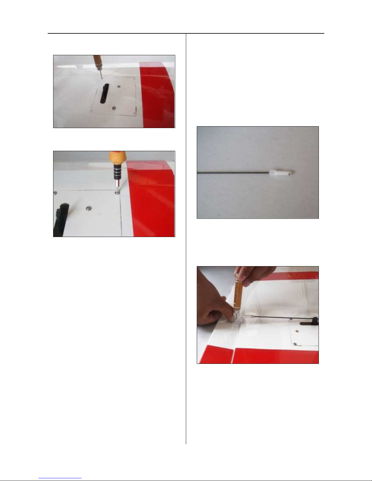
Step3. Glue the two blocks onto the servo hatch.
Step4. Use a 1.5mm (.06in) drill bit to drill two holes
on the hatch as shown. The location for the holes
should be in the central point of the blocks.
Step5. Use two M2.5*8mm (.3in) self-tapping screws
to secure the block wont loose.
Step6. Use four M2.5*8mm (.3in) self-tapping screws
to secure the servo to the mounting blocks.
Step7. Thread the servo extension through the wing.
www.valuehobby.com/stylus-sport-60.html
- 8 -
Step8. Use a 1.5mm (.06in) drill bit the drill the
mounting hole as shown.
Step9. Use four M2*8mm (.3in) self-tapping screws to
install the servo hatch to the wing.
Step10. Repeat the previous steps to finish the other
aileron servo installation.
Section 3: Aileron Linkage Installation
Required parts and hardware:
Aileron Servo pushrodΦ1.8*150mm (5.9in) 2pcs
Keeper 2pcs
Clevis 2pcs
Control horn 2pcs
Nut plate 2pcs
Philips roundhead screw M2*16mm (.6in) 4pcs
Step1. Thread the clevis into pushrod.
Step2. Attach the clevis to the control horn. Position
the control horn on the aileron. Use the pushrod wire
as a guide to align the horn to the servo arm. Position
the horn so the holes align with the hinge line. Use a
1.5mm (.06in) drill bit to drill the holes as shown.

www.valuehobby.com/stylus-sport-60.html
- 9 -
Step3. Use two M2*16mm (.6in) Phillips round head
screws and nut plate to install control horn on the
aileron.
Step4. Center the aileron. Use a felt-tipped pen to
mark the pushrod where it crosses the arm servo.
Step5. Bend the pushrod at the mark and cut the
excess wire. Use a keeper to secure the pushrod to
the arm servo.
Step6. Repeat the step 11 to 14 to finish the other
aileron servo installation.
Section 4: Wing Installation
Required parts and hardware:
Wing panels
Wing joiner 1pcs
Wing bolts plate
Philips roundhead screw M4*35mm (1.4in) 2pcs
Washer Φ4 2pcs
Step1. Insert the wing joiner into the left wing panel.
Use a felt-tipped to draw a line on the joiner against
the wing as shown.
Step2. Use a brush to apply some epoxy to one half of
the joiner. Make sure to coat the front, back, top and
bottom of the joiner with epoxy.
Step3. Slide the wing joiner into the wing panel.

www.valuehobby.com/stylus-sport-60.html
- 10 -
Step4. Use a brush to apply some epoxy to the
exposed wood on the wing foot and the other half of
the joiner.
Step5. Slide two wing panels together, and use the
low-tack tape to hold them tightly together until the
epoxy fully cures.
Step6. Use a drill bit or screwdriver to locate the
mounting holes as shown.
Step7. Align the hole on the plate to the hole on the
wing as shown, and use a felt-tipped pen to trace the
outline of the wing bolt plate.
Step8. Use a hobby knife to trim the covering inside
the lines drawn in the previous step.
Step9. Apply some epoxy on the bare wood.
Step10. Use two M4*35mm (1.4in) round head
screws and two Φ4 washer to secure the wing to the
fuselage.
Note: you can finish step9 and step10 later.
www.valuehobby.com/stylus-sport-60.html
- 11 -
Section 5: Horizontal Stabilizer &
Elevator installation
Required parts and hardware:
Horizontal stabilizer
Elevator
Joiner
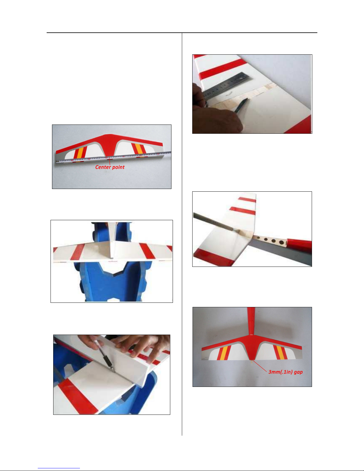
Step1. Use the ruler and a felt-tipped pen to locate
the center point in the trailing edge of the horizontal
stabilizer.
Step2. Position the horizontal stabilizer and fuselage
as shown. So the center point on the stabilizer should
be in the center line of the fuselage.
Step3. Push the stabilizer against the fuselage, and
use a felt-tipped pen to trace the outline of the
fuselage.
Step4. Use a hobby knife to trim the covering inside
the lines drawn in the previous step.
Step5. Apply some epoxy on the bare wood in the
fuselage and stabilizer as shown, and glue the
stabilizer onto the fuselage. (Note: Make sure the
horizontal stabilizer is parallel with the main wing,
hold the horizontal stabilizer until the epoxy fully
cures.)
Step6. Glue the fin mounting block onto the fuselage
as shown. (Make sure there is 3mm (.1in) gap
between the block and the trailing edge of the
stabilizer.)

www.valuehobby.com/stylus-sport-60.html
- 12 -
Step7. Use a 2.5mm (.1in) drill bit to drill the hole in
the elevator as shown.
Step8. Insert three hinges into the slot in the leading
edge of the elevator.
Step9. Apply some glue into the slot.
Step10. Insert the end of the joiner into the elevator.
Slide the elevator and stabilizer together through the
hinges. Align the elevator tips with the stabilizer tips.
Once satisfied, use a felt-tipped pen to mark the
location for the other end of the joiner as shown.
Step11. Repeat step 7 to step 8 on the other elevator
panel.
Step12. Install the joiner on the other elevator panel.
Again slide the elevator and stabilizer together. Use
thin CA to saturate the hinges, including the top and
bottom of the hinges.

www.valuehobby.com/stylus-sport-60.html
- 13 -
Section 6: Fin, Rudder and Tail wheel
Installation
Required parts and hardware:
Fin
Rudder
Triangle Stock 2pcs
Fin mounting block
Tail wheel assembly
Step1. Locate the two triangle stock. Align one stock
with the edge of the fin. Use a felt-tipped pen to trace
the stock on the fin.
Step2. Use a hobby knife and a ruler to trim the
covering along the line drawn in the previous step.
Step3. Repeat the step 12 and 13 for the other
triangle stock.
Step4. Use the epoxy to glue two triangle stock to the
fin as shown.
Step5. Position the fin on the horizontal stabilizer. Use
a felt-tipped pen to trace the outline of the fin.

www.valuehobby.com/stylus-sport-60.html
- 14 -
Step6. Use a knife to remove the coverings inside the
lines drawn in the previous step.
Step7. Use a brush to apply some epoxy on the bare
wood of the horizontal stabilizer and the bottom of
the fin as shown.
Step8. Glue the fin onto the horizontal stabilizer.
(Note: use a square to make sure that the fin is
perpendicular to the horizontal stabilizer).
Step9. Assemble the tail wheel as shown.
Step10. Insert the hinges into the slot in the rudder,
and mark the location where it is 25mm (1.0in) from
the rudder foot.

www.valuehobby.com/stylus-sport-60.html
- 15 -
Step11. Use a 2.5mm (.1in) drill bit to drill the hole
and use a hobby knife to cut a groove as shown.
Step12. Install the tail wheel assembly in the rudder.
Apply some thin CA into the hinge slots and groove.
Step13. Secure the tail wheel bracket to the fuselage
Section 7: Elevator & Rudder Servo and
Linkage Installation
Required parts and hardware:
Pushrod Φ1.8*900mm (35.4in) 2pcs
Clevis 2pcs
Control horn 2pcs
Nut plate 2pcs
Phillips roundhead screw M2*16mm (.6in) 4pcs
Pushrod connector 2pcs
Elevator servo (sold separately)
Rudder servo (sold separately)
Step1. Install a pushrod connector to the servo arm as
shown.
Step2. Install the elevator servo to the servo
mounting tray.
Step3. Thread the elevator pushrod wire through the
tube. Install the control horn to the elevator as shown.
(Bend the pushrod if necessary.)

www.valuehobby.com/stylus-sport-60.html
- 16 -
Step27. Center the elevator and servo arm. Attach the
pushrod to the pushrod connector.
Step28. Install the rudder control horn to the rudder.
Step29.Center the rudder and rudder servo arm.
Attach the pushrod to the servo arm through the
connector as shown.
Section 8: Engine Installation
Required parts and hardware:
Tank assembly 360cc
Engine mount 1 pair
Phillips roundhead screw M4*25mm (1.0in) 4pcs
Washer Φ4 4pcs
Step1. Attach the engine to the firewall with four
M4*25mm (1.0in) roundhead screws.
Step2. Position the engine on the mount, adjust the
engine so that the distance between the firewall and
drive washer is 140mm (5.5in). (In this step, attach
the pushrod to the throttle arm and thread the
pushrod through the hole in the firewall.)
Step3. Mark the location for engine mounting bolts.
Drill the holes on the mark and install the engine on
the mount using the screws provided with the engine.

www.valuehobby.com/stylus-sport-60.html
- 17 -
Step4. Install the throttle servo on the servo tray.
Electronically adjust the throttle arm and servo arm
to make them move rightly. Secure the pushrod to
the servo arm.
Section 9: Fuel Tank Installation
Required parts and hardware:
Fuel tank assembly
Step1. The fuel tank can be assembled as a two line
system consisting of a vent (pressure) line to the
muffler and a carburetor line. Filling and emptying of
the tank would need to be done through the
carburetor line, or an optional fuel fill valve. The tank
can also be assembled as a three line system having a
vent line, carburetor line, and fill line. If install a fill
line, puncture the top of the stopper above the
sealed off fuel tube hole. The fill and carburetor lines
should extend out 13mm beyond the stopper and the
vent line should be bent upwards and left uncut.
With the tubes installed in the stopper, the stopper
plates loosely in place with the PM3x25mm screw to
hold the assembly together.
Step2. Fit the stopper assembly into the tank with the
vent line pointing toward the top of the tank, but not
touching. The fuel tubing and clunks (fuel pickup) on
the carburetor and fill lines should almost reach the
back of the tank but not touch. The clunks must be
able to move freely inside the tank when assembled.
Adjust the length of the fuel tubing accordingly. When
satisfied, tighten the PM3x25mm screw in the
stopper to secure it in place (do not over-tighten).
Mark the side of the tank that must face up when
installed in the plane. We also suggest marking the
tubes in the stopper.
Step3. Insert the tank into the fuselage with the
correct side facing up. The fuel tubing should be
routed through the hole in the center of the firewall.

www.valuehobby.com/stylus-sport-60.html
- 18 -
Section 10: Electric Motor Installation
Required parts and hardware:
Electric motor mount
Socket cap machine screw-M4*16mm (.6in) 4pcs
Nut M4 4pcs
Washer---Φ4mm (0.16in) 4pcs
Step1. Install the electric motor mount to the firewall
with four M4*16mm (.6in) socket cap screws and
fourΦ4mm (0.16in) washers.
Step2. Use drill bit to drill the holes for mounting the
electric motor.
Step3. Install the electric motor to the motor mount
with the screws provided with the motor.
Section 11: Landing Gear Installation
Required parts and hardware:
Landing Gear 1pcs
Philips roundhead screw-M4*12mm (.5in) 3pcs
Washer-Φ4mm (.16in) 3pcs
Main wheels-Φ65mm (2.6in) 2pcs
Socket cap machine screw-M4*35mm (1.4in) 2pcs
Locknut-M4 4pcs
Step1. Use a M4*35mm (1.4in) socket head screw as
the axle. Attach the wheel to the axle with a M4
locknut.
Step2. Use two M4 locknuts to attach two assembled
wheel to the landing gear.

www.valuehobby.com/stylus-sport-60.html
- 19 -
Step3. Use three M4*12mm (.5in) Phillips roundhead
screw and three Φ4mm (.16in) washers to secure the
landing gear to the fuselage as shown.
Section 11: Canopy Installation
Required parts and hardware:
Canopy
Self-tapping screw M2.5*8mm (.3in) 4pcs
Step1. Use a 1.5mm (.06in) drill bit to drill four holes
for mounting through the canopy.
Step2. Use four M2.5*8mm(.3in) self-tapping screws
Install the canopy to the fuselage as shown.
Section 11: Setting CG and Control
throws
Recommended CG
For the first flights, the recommended Center of
Gravity location is 91mm (3.6in) behind the leading
edge of the wing against the fuselage. Use the battery
pack, moving it forward or backward, to achieve the
correct balance
.
Low / Precision Rates (in degrees) and
Corresponding Exponential
Aileron:
20° up / 20° down Expo: 40%
Elevator:
20° up / 20° down Expo: 25%
Rudder:
30° left / 30° right Expo: 30%
Note: that Futaba and Hitec radios require
NEGATIVE exponential, while JR and
Spektrum use POSITIVE exponential.

www.valuehobby.com/stylus-sport-60.html
- 20 -
www.valuehobby.com
2012-11-6
 Loading...