


51in Aerobatic Series
F3A Oasis
Almost-Ready-to-Fly
Instruction Manual
Specifications
Wingspan: 50.6 in (1285mm)
Length: 53.1 in (1350mm)
Wing Area: 480 sq in (31sq dm)
Flying Weight: 3.5 lb (1600g)

http://www.valuehobby.com/
2
Dear Customer,
Congratulations on your purchase of 51in F3A Oasis from Value Hobby. We thank you for your generous
support, and hope you enjoy your new airplane.
At V alue Hobby, we hope to offer competitive prices, good performance, and products that you can setup
and use with ease. That’s why we extensively researched and tested this airplane, and suggested all the
products necessary for you to setup properly. We understand that you have many choices when
purchasing, and we are grateful you choose to buy from us.
As vendors, one of the most gratifying things for us is to hear from our customers. We would welcome
any suggestion to help us improve. Please make us aware of any errors and imperfections in the
airplane or the instructions, or about the setup that we suggested. We hope you’ll find our setup
suggestions to be helpful, and enjoy flying your new airplane. Please feel free to contact us at (630)
948-0947 or email us at support@valuehobby.com
Disclaimer
By purchasing and/or building this model, user assumes ALL liability and risk involved with this product.
This model should be built and flown by an experienced pilot and only flown at AMA sanctioned sites.
Value Hobby guarantees this model to be free of defects in materials and workmanship at the date of
purchase. This warranty does not cover any parts damaged by use or modifications. In no way shall
Value Hobby’s liability exceed the original cost of the purchased model. Further, Value Hobby reserves
the right to modify this warranty without notice. Value Hobby has no control over the final stages of
assembly or the material used for the final assembly. No liability shall be assumed nor materials used for
the final user-assembled product. By the act of using the final product the user accepts all resulting
liability. Value Hobby, as a R/C product vendor, provides a top quality airplane and instructions to
complete the model. The quality and flight characteristics of the finished model depends greatly on how
it is built; we cannot guarantee the performance for the completed model and representations are
expressed or implied as to the performance of the completed model. If the buyer is not prepared to
accept the liability associated with the use of this product, the buyer is advised to return this kit
immediately, in new and unused condition.
Safety in Assembly
During assembly of this aircraft, you will be asked to use sharp knives and hobby adhesives. Please
follow all safety procedures recommended by the manufacturers of the products you use, and always
follow these important guidelines:
AL WAYS protect your eyes when working with adhesives, knives, or tools, especially power tools. Safety
glasses are the best way to protect your eyes.
ALWAYS protect your body, especially your hands and fingers when using adhesives, knives, or tools,
especially power tools. Do not cut toward exposed skin with hobby knives. Do not place hobby knives on
tables or benches where they can roll off or be knocked off.
AL WAYS have a first-aid kit handy when working with adhesives, knives, or tools, especially power tools.
ALWAYS keep hobby equipment and supplies out of the reach of children.

http://www.valuehobby.com/
3
Safety in Flying
This is NOT a toy! It is a very high-performance RC airplane capable of high speeds and extreme
maneuvers. It should only be operated by a competent pilot in a safe area with proper supervision.
ONLY fly your aircraft in a safe, open area, away from spectators and vehicles–and where it is legal to
fly.
NEVER fly over an unsafe area, such as a road or street.
Never fly too close to yourself or spectators.
Never run your motor inside a house or building with the propeller attached – Remove the prop for
safety.
Required Items
CA Glue – Thin and Thick
Epoxy glue
Hobby Knife
Small Phillips Screwdriver
Set Metric Allen Wrenches
Scissors
Small Pliers
Wire Cutters
Masking tape
Optional – Heat gun
Before Starting Assembly
Examination
Unpack your airplane and examine the components. Check for damage of any kind. If you see any
damage, please contact Value Hobby immediately.
Covering
Your airplane was packed in plastic at the factory without any wrinkles in the covering. You may notice
some wrinkles now; more likely, you will notice a few in a day or two or the first time you take the plane
out to the flying field. These wrinkles are the result of wood shrinkage and/or expansion. Balsa wood
changes size and shape slightly as it is exposed to varying humidity in the air. This is a natural property
of balsa wood. As your airplane adjusts to the weather in your part of the world, wrinkles may appear and
disappear. Wrinkles may be removed with the gentle application of heat to the covering material on your
airplane. The best tool to use is a hobby heat gun. Apply the heat gently: the covering material will shrink
as you apply the heat, and this will remove the wrinkles. BE CAREFUL! Too much heat applied too
quickly can damage the covering, either by causing it to pull away from the wood at seams and corners
or even by melting it. The covering will shrink at low temperature with patient application of heat.
Wrinkles in the covering DO NOT affect flight performance.
Remove the canopy before attempting to use heat on your covering! The canopy is made of
thermo-activated plastic and WILL deform with the application of heat. Do not apply heat to the canopy.
If you need to clean your airplane, we recommend using a damp towel. The paint used on the canopy
and cowl is not safe for all cleaners. In particular, DO NOT use alcohol on these parts, it will remove the
paint.

http://www.valuehobby.com/
4
Recommended Setup
Parts of the Airplane
Configuration Model Qty
Radio 4 channel 1
Motor Size
GForce G15 Brushless Outrunner Motor(2820
KV800-1100)
1
Speed Control 60A PRO Brushless ESC with UBEC 1
Recommended
Battery(LiPO)
GForce Elite Series 35C 2200mAh 3S11.1V or 4S14.8V
LiPO
1
Prop Size APC 14X7 or APC 13 X6.5 1
servos 17gX1+9gX3 4
Y-Harness
Universal Servo Y-Harness (300mm)11.8-Inch (Futaba
"J" and JR Compatible)
1
Extension
Universal Servo Extension (600mm)23.6-Inch (Futaba "J"
and JR Compatible)
2
Charger GT POWER X-CHARGER C6 6S LiPO Charger 1

http://www.valuehobby.com/
5
Section 1: Aileron Installation
Step 1. Locate the hinges from the hardware pack. Test fit the four aileron hinges on the
aileron. Verify the correct position and alignment of the aileron with the wing panel.
Step 2. Glue each of the four hinges in the aileron with some drops of thin CA.

http://www.valuehobby.com/
6
Step 3. Carefully glue each of the four hinges into the wing panel with thin CA.
Step 4. Move the aileron up and down several times to work the hinges and check for proper
movement.
Step 5. Repeat steps 1 through 4 for the remaining wing panel.

http://www.valuehobby.com/
7
Section 2: Aileron Servo & Control Horn Installation
Step 1. Locate the following hardware. (Servos and Y-Harness need to be purchased
separately).
Step 2. Remove the covering over the aileron servo opening as shown.

http://www.valuehobby.com/
8
Step 3. Install the servo onto the wing panel. Glue the fiberglass horn onto the aileron with
medium CA.

http://www.valuehobby.com/
9
Step 4. Inst all the carbon fiber pushrod and make the final adjustment as shown in the picture.
Step 5. Repeat steps 1 through 4 for the other wing panel.

http://www.valuehobby.com/
10
Section 3: Rudder Installation
Step 1. Insert three hinges in their appropriate slots on the rudder. Verify the alignment and
glue them with some drops of thin CA.

http://www.valuehobby.com/
11
Step 2. Locate the rudder and carefully glue the hinges with some drops of thin CA.

http://www.valuehobby.com/
12
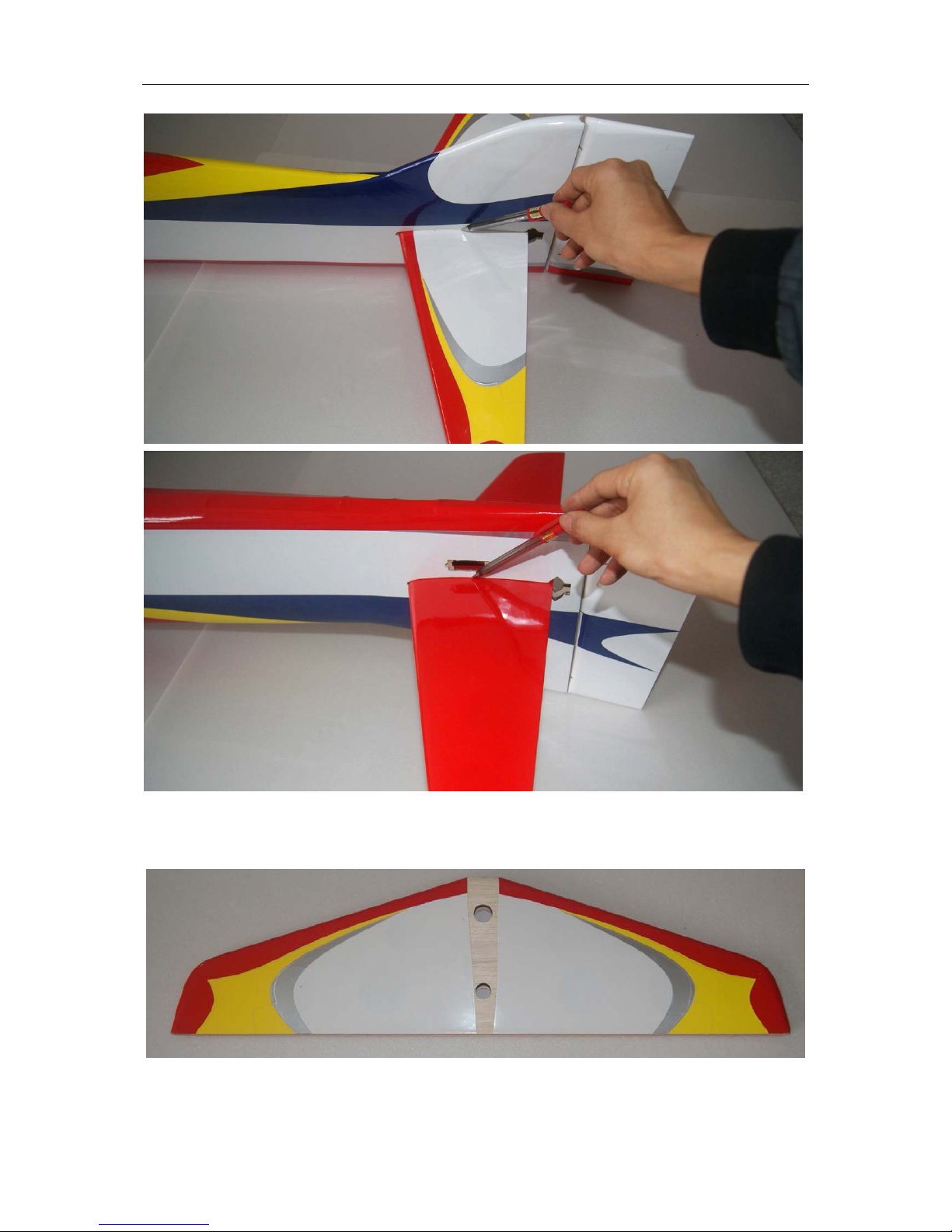
Section 4: Elevator Installation
Step 1. Test fit the horizontal stabilizer in the fuselage. It should be centered between the left
and right side. Using the wing tube as a guide, measure the distance from the tube to the
stabilizer as shown. Make sure this distance is also the same on the left and right sides.
http://www.valuehobby.com/
13
Step 2. Trace the outline where the horizontal stabilizer joins the fuselage using a marker.
Step 3. Using the outline from the last step, remove the covering over the horizontal stabilizer
that goes into the fuselage.

http://www.valuehobby.com/
14
Step 4. Insert in the elevator the four hinges into their appropriate slots and verify the correct
position and alignment of the elevator with the stabilizer. Then carefully glue the hinges, with
some drops of thin CA, in the elevator only.

http://www.valuehobby.com/
15
Step 5. Insert carefully the elevator through the fuselage.
Step 6.Insert carefully the stabiliser into fuselage space.
Locate the elevator hinges into the
stabiliser.

http://www.valuehobby.com/
16
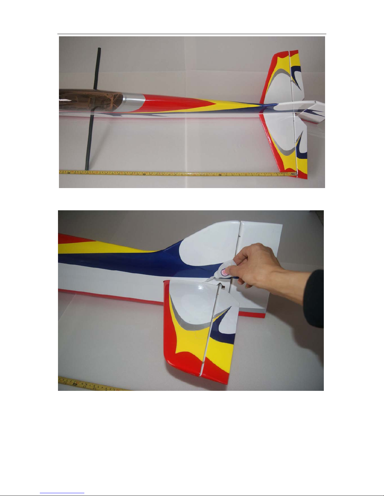
Step 7. Flex the elevators 45 degrees up and down, make sure the elevator can move freely.
Then glue the hinges with thin CA.
Step 8. Slide the carbon fiber wing tube into the fuselage, and carefully check the alignment of
the stabilizer with the fuselage.
http://www.valuehobby.com/
17
Step 9. Once satisfied with the alignment, glue the stabilizer onto the fuselage with thin CA.

http://www.valuehobby.com/
18

http://www.valuehobby.com/
19
Section 5: Rudder Servo & Control Horn Installation
Step 1. Locate the items below from the hardware pack. The servo and extension are not
included and need to be purchased on your own.
Step 2. Install the servo into the fuselage. Glue the fiberglass horn into the rudder with
medium CA.

http://www.valuehobby.com/
20
Step 3. Install the carbon fiber pushrod, and make the final adjustment as show in the picture.

http://www.valuehobby.com/
21
Section 6: Elevator Servo & Control Horn Installation
Step 1. Locate the items below from the hardware pack. The servo and extension are not
included and need to be purchased on your own.
Step 2. Install the servo into the fuselage. Glue the fiberglass horn onto the elevator with
medium CA.

http://www.valuehobby.com/
22
Step 3. Install the carbon pushrod, and make the final adjustment as shown in the picture.

http://www.valuehobby.com/
23
Section 7: Tail Wheel Installation
Step 1. Cut a 30mm slot on the rudder; Drill a hole in the rudder for tail wheel wire. This hole
position must be precise so the tail wheel wire can be installed.

http://www.valuehobby.com/
24
Step 2. Secure the tail wheel. Carefully apply in the rudder-slot a few drops of medium CA, as
shown in the picture.

http://www.valuehobby.com/
25
Section 8: Landing Gear & Wheels Installation
Step 1. Locate the parts of the main landing gear from the hardware pack.
Step 2. Install the main wheels on the wheel pants as shown below.
Step 3. Repeat steps 2 for the other side of the landing gear.

http://www.valuehobby.com/
26
Step 4. Install the landing gear legs into the fuselage with the provided 3mm screws as shown
below.

http://www.valuehobby.com/
27
Section 9 – Electric Motor and ESC Installation
Step 1. We recommend Gforce G15 (2820) motor for this airplane (not included).
Step 2. Inst all your brushless motor onto the firewall using the 4 black 3mm allen-hea d screws
included in your kit. Make sure the motor spins freely . Depending on the size of the shaf t collar
on your motor, you may need to remove a small amount of wood from the firewall for free
rotation.
Step 3. Install the ESC inside the motor box or inside the fuselage, depending on the
requirement of balancing the CG.

http://www.valuehobby.com/
28
Section 10: Cowling Installation
Step 1. To mount the cowl, first locate the 4 small plywood rectangles on the inside of the
fuselage sides at the front of the fuselage. The cowl-mounting screws are screwed into these
plywood pieces. In order to know where these plywood rectangles are after we install the cowl,
tape small pieces of paper over the plywood rectangles as shown.
Step 2.
Install the cowl and align carefully so that the spinner matches the cowl a s desired. B e
sure canopy hatch is in place for this step.

http://www.valuehobby.com/
29
Step 3. Use a hobby knife to make small holes through the paper strips into the cowling. This
locates the cowl screws accurately so that they will screw into the plywood. Use the 4 small
remaining wood screws to mount the cowl.
Step 4. Fix carefully the prop and spinner as shown below.

http://www.valuehobby.com/
30
Section 11: Wings installation
Step 1. Install the Wings as shown below.

http://www.valuehobby.com/
31
Section 12: Setting CG and Control Throws
Recommended CG
For the first flights, the recommended Center of Gravity location is 165mm behind the leading
edge of the wing against the fuselage. Use the battery pack, moving it forward or backward, to
achieve the correct balance.
Control throws
For the AILERONS we recommend the following throws:
High rate: 40° left & right
Normal flight: D/R: 30% Expo: 20%
Snap: D/R: 100% Expo: 90%
Spin & 3D: D/R: 100% Expo: 90%
For the ELEVATOR we recommend the following throws:
High rate: 40° up & down
Normal flight: D/R: 30% Expo: 30%
Snap: D/R: 40% Expo: 50%
Spin & 3D: D/R: 100% Expo: 95%
For the RUDDER we recommend the following throws:
High rate: 40° left & right
Normal flight: D/R: 40% Expo: 60%
Snap: D/R: 50% Expo: 70%
Spin & 3D: D/R: 100% Expo: 90%
Note: that Futaba and Hitec radios require NEGATIVE exponential, while JR and Spektrum
use POSITIVE exponential.
Range test your radio
step1. Before fly, be sure to range check your radio as manufacturer’s instruction
manual of your radio-system recommand.
step2.
Double-check all controls (aileron, elevator, rudder and throttle) move in the
correct direction.
step3. Be sure that your LiPO battery is fully charged.

http://www.valuehobby.com/
32
Finally...
Enjoy Your F3A Oasis!
have a nice flight!
 Loading...