


3002783/01
Date: June 2002.
© Valor Heating
Safety Upgrade Instructions
These instructions are for the
Valor Legend Ultra
(Model 837 AN and 837 AP)
Important: Switch the appliance off, isolate the gas supply to the appliance and
ensure that the appliance is completely cool before continuing any further.
1. Removal of Fascia
Cast Iron Fascia
1. Unscrew and remove the ignition bar knob
(See figure 1).
2. Remove the lower front casting by lifting and
pulling forward (See figure 2).
3. Remove two screws located behind the upper
decorative casting (See figure 3).
4. Remove the Fascia by gentle pulling the top of
the fascia forward. Two retaining clips hold the
top of the fascia. Once clear of these the fascia
can be lifted clear of the lower bottom fascia
brackets (See figure 4)
Figure 1. Removal of ignition bar
knob.
Figure 2. Removal of lower front
casting.

Safety Upgrade Instructions
Standard fascia – three or four sided.
1. Unscrew and remove
the ignition bar knob
(See figure 1).
2. Remove the Fascia by
gentle pulling the top
of the fascia forward.
Two retaining clips
hold the top of the fascia. Once
clear of these the fascia can be
lifted clear of the lower bottom
fascia brackets (See figure 4).
Figure 3. Removal of Screws on cast Iron fascia.
Figure 4. Fascia Removal on Cast Iron and
Standard fascia.
Page 2

Safety Upgrade Instructions
b
2. Removal of bushing from ignition bar
For models fitted with a locating bracket (See figure 5)
1. Remove the self-tapping screw from the
ignition bar locating bracket (See figure 5).
2. Place a suitable flat instrument on the
underside of the bushing and lift the bushing
clear of the mounting bracket (see figure 6).
3. Pull the ignition bar forward and clear of the
mounting bracket.
4. Remove bushing from ignition bar by sliding
up around bend and off bar. If bushing is too
tight to slide off, cut off bushing with a utility
knife.
5. With the bushing removed, push the ignition
bar back into the mounting bracket.
6. Replace the locating bracket and secure using
the self-tapping screw removed previously.
For models NOT fitted with a locating bracket
(See figure 5)
7. Place a suitable flat instrument on the
underside of the bushing and lift the bushing
clear of the mounting bracket (see figure 6).
8. Pull the ignition bar forward and clear of the
mounting bracket.
9. Remove bushing from ignition bar by sliding
up around bend and off bar. If bushing is too
tight to slide off, cut off bushing with a
utility knife.
10. With the bushing removed, push the ignition
bar back into the mounting bracket.
Figure 5. Removal of Screw from
locating bracket.
Figure 6. Removal of Bushing.
11. Position the locating bracket with its sides in
line with those of the mounting bracket (See
figure 7). Mark the position of the hole.
12. Remove the bracket and drill a 3.5mm (1/8
in) hole
13. Reposition the location bracket
and secure using a self-tapping screw.
Figure 7. Fitting the locating
racket.
Page 3

Safety Upgrade Instructions
3. Replacing the Gas Valve
Refer to figure 8.
1. Loosen the screw attaching the ignition bar to the top of the gas valve.
2. Lift the ignition bar clear of the gas valve spindle.
3. Supporting the elbow with a wrench, unscrew the nut to the inlet elbow on the gas
valve.
4. Unscrew the pilot line nut from the gas valve. Pull the pilot line clear of the valve.
5. Unscrew and remove the thermocouple
nut connecting the thermocouple to the
interrupter block at the base of the gas
valve.
6. Remove the microswitch leads from
the interrupter block. Do not pull on
the leads. Grip the terminals close to
the interrupter block and gently pull
the leads clear of the interrupter block.
This will avoid damage to the leads.
7. Unscrew and remove the interrupter
block.
8. Supporting the connector with a
wrench, unscrew the pipe nut below
the thermostat valve.
9. Unscrew and remove the brass nut at
the top of the gas valve.
10. The gas valve can now be removed.
11. Supporting the elbow, unscrew and
remove the nut holding the thermostat
pipe to the elbow.
12. Place the old valve away from the
work area.
13. Obtain the replacement gas valve and
fit to the appliance in reverse to
above.
When fitting the new valve it may be easier if the screws at the top of the
regulator support bracket are loosened. These screws must be tightened after
fitting the new gas valve.
Figure 8. Gas Valve
Page 4

Safety Upgrade Instructions
Important Note:
When connecting the ignition bar to
the top of the gas valve it is important
that the arm of the microswitch is
behind the ignition arm (See figure 9).
Ensure that when the ignition bar is
depressed the microswitch arm does
not pass over the top of the ignition
arm. If it does, or appears likely to
during future use, then the angle of the
ignition arm must be adjusted. Only
make the adjustment if absolutely
necessary. Do not overbend the
ignition arm.
Figure 9. Microswitch arm location
The screw at the base of the ignition
bar must be against the ‘D’ flat on the gas valve spindle.
4. Replacing the electronic spark generator battery
Refer to figure 10.
1. Remove the battery from the electronic spark generator. To do this simply grip the
battery at the left hand side, lift and pull to the left.
2. Remove the old battery from the work area.
3. Obtain a new battery
and fit this into the
electronic spark
generator. To do this
hold the battery so
that the positive
terminal is towards
the rear of the
appliance. Slide the
battery in from the
left side. When the
battery stops sliding
push it down so that
it locates against the
left-hand retainer.
Figure 10.Battery Replacement
Page 5

Safety Upgrade Instructions
5. Relief Panel operation
The relief panels on the underside of the firebox should be held in place by their spring
retainers, but should be capable of opening when the pressure within the firebox becomes
too great.
• To check the operation of the
relief panels push them down
from inside the firebox. They
can be accessed behind the
lower ceramic support by first
removing the two cross logs
and front log. (See figure 11).
Push down by 40-50mm and
ensure that they open easily
and freely. There should be
no restriction.
• If there is any restriction or
metallic scrapping sound then
the relief panels may be
coming into contact with the
stop plates. These are located
on the underside of the
firebox behind the relief
panels and are to ensure that
the springs are not over bent
during operation. If the relief
plate is coming into contact
with the stop plate then push
the bottom of the stop plate
towards the rear of the appliance by about 1/8th inch. Try the operation of the relief
plate and ensure that it closes against the base of the firebox. It is Important that
Figure 11. Relief panels
the relief doors operate easily and freely before leaving the
appliance.
Page 6

Safety Upgrade Instructions
6. Adjusting the height of the ignition bar
When refitting the Fascia it is important that the height of the ignition bar is
adjusted to ensure smooth operation.
The height of the ignition bar can be adjusted to suit the slot in the fire front. The
adjustment must be made before the window is refitted as follows:
1. Locate slots in the fascia over the claws at the sides of the main appliance (figure.
12).
Figure 12. Fascia locating
2. Angle the fascia up and turn the ignition bar to test if it will project through the slot
in the fascia.
Page 7

Safety Upgrade Instructions
3. If the ignition bar does not
locate satisfactorily
through the fascia, loosen
the screw securing the
ignition bar sleeve (figure.
13).
4. Adjust the height of the
ignition bar so that it can
rotate freely through the
slot. Retighten the sleeve
screw.
5. The thermostat wheel
height can be adjusted by
simply sliding it up or
down the spindle and the
tightening the bushing
below so that it is flush
against the wheel (figure
13)
6. Remove the fascia.
Figure 13 Ignition bar adjustment screw
Page 8

Safety Upgrade Instructions
7. Final Review
Replace the ceramic fuel effect bed as below
1. Place the lower rear
log in the support cradles at
the back of the firebox (See
figure 14).
Figure 14. Lower rear log
2. Place the upper rear log on top of
the lower rear log. The pegs in the lower
log locate in the holes in the upper log
(figure 15).
Figure 15. Upper rear log
Page 9
Safety Upgrade Instructions
3. Place the front
log in the opening of
the firebox base cover.
Slide the log forward
as far as it will go (See
figure 16).
Figure 16. Front log
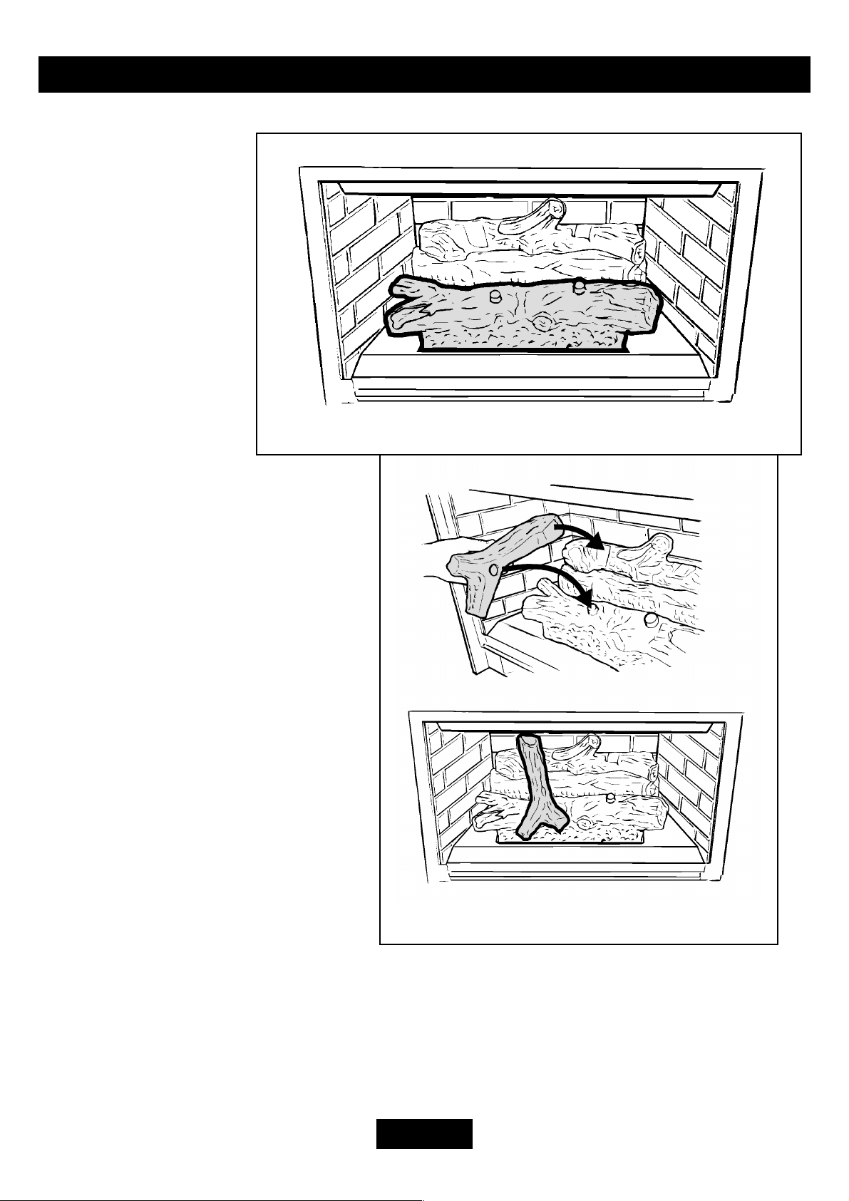
4. Place the left cross log
(stamped “L” underneath) over the
front and rear logs. Locate the cross
log over the peg in the front log and
into the channel in the rear log (See
figure 17).
Figure 17. Left cross log
Page 10

Safety Upgrade Instructions
5. Place the right front log
(stamped “R” underneath) over the
other logs. Locate it over the peg in
the front log and into the channel
in the rear log (See figure 18).
Figure 18. Right cross log
• Without replacing the glass window, fit the fascia. Check for smooth operation of the
ignitor lever. If the ignitor lever contacts the fascia at its lowest depressed position,
adjustment is required. Insert a screwdriver between the firebox and fascia (through
the void space where the glass window would be) and loosen the set screw halfway up
on the ignitor bar. Adjust the ignitor lever up to almost the top of the opening in the
fascia and tighten set screw. Re-check operation of ignitor lever to ensure no contact
with fascia in the upper released or lower depressed position. Remove fascia again.
• With the glass window still removed, re-connect the gas supply to the heater and carry
out a leak test on all of the gas connections up to the control valve. Next light the
fireplace and leak test between the control valve and the burners. Shut off the
fireplace.
• Replace the glass window as in the Installation and Owner’s manual. Ensure window
is completely down in lower support track and all three upper buckles secured.
• Fit the Fascia and ignition bar knob.
• Conduct full operational checks as in the Installation and Owner’s manual.
Page 11

Safety Upgrade Instructions
Advise the customer that: -
1. The battery should be replaced each season.
2. If for any reason the fascia has been removed the smooth operation of the ignition
lever must be checked. If it is not smooth then the appliance must not be used until
rectified by a qualified person.
Page 12
 Loading...