

1
Part 590839
ZERO CLEARANCE KIT
for Models 737UN, 737UP & 737BN
INSTALLATION INSTRUCTIONS
1. GENERAL
This kit must be used when installing heater Model 737UN, 737UP or 737BN into an enclosure constru c ted of
combustible material. The heater must also be connected to an approved flue pipe.
This kit ha s been designed to act a s a fireplace opening for i nstallation durin g the constructi on of the appliance enclosu re.
The heater i s d esigned to be fitted into the openin g after the wal l s a nd hearth h ave been fini shed.
2. FRAMING.
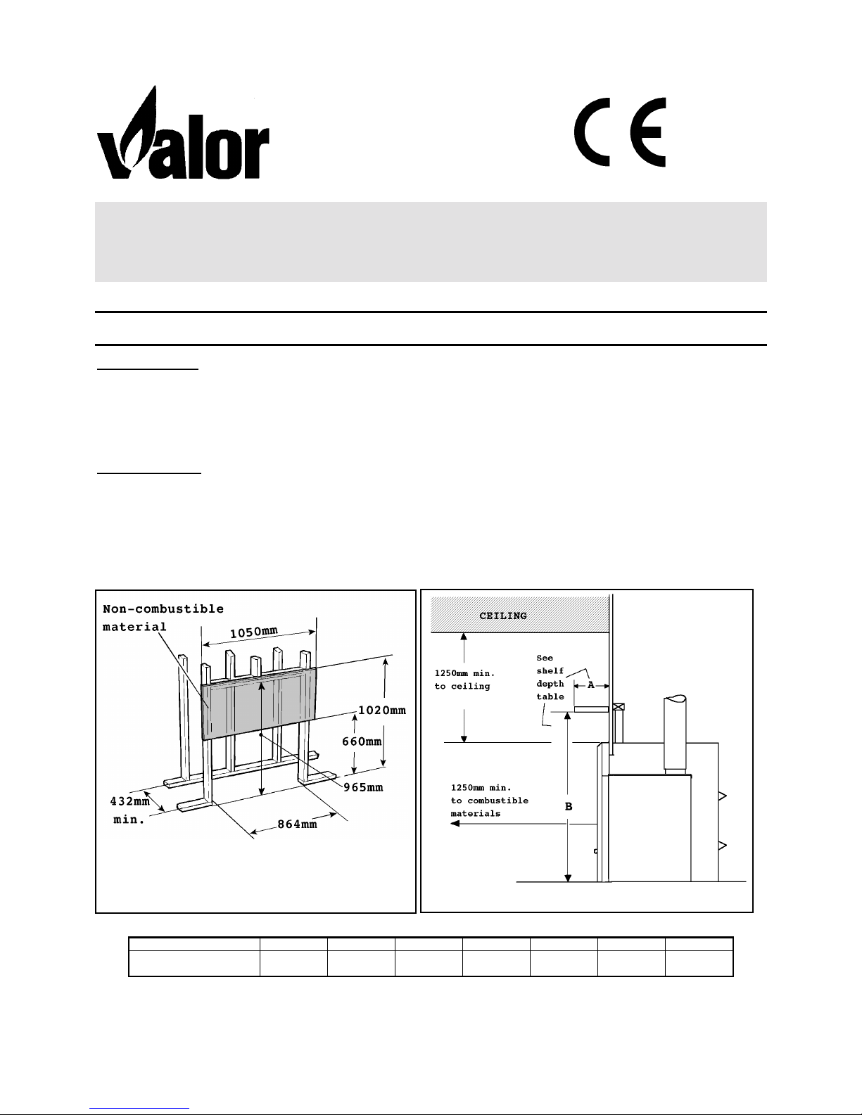
Minimum clearances to combustible materia ls and fra mi ng details ar e sh own in fig.1,.
Though not mandatory for this appliance, if the bottom of the appliance is at floor level, we recommend that there is a
hard su rfaced hea rth area i n front of the f ireplace for both aesthetic a nd mainten ance purposes. This may be finished in
brick, ceramic tile, marble, etc.
To enable the heater to be installed correctly the height of the finished floor surface in front of the appliance
must be known before constructing the frame. The bottom of the z e ro cl e arance k i t must be installed at the
height of the finished floor surface.
SHELF D EPTH “A” 25mm 50mm 75mm 100mm 125mm 150mm 175mm
HEIGHT FROM BASE OF
HEATER “B”
960mm 1010mm 1040mm 1090mm 1140mm 1190mm 1240mm
600A711/02
Fig.1
Fig. 2
2
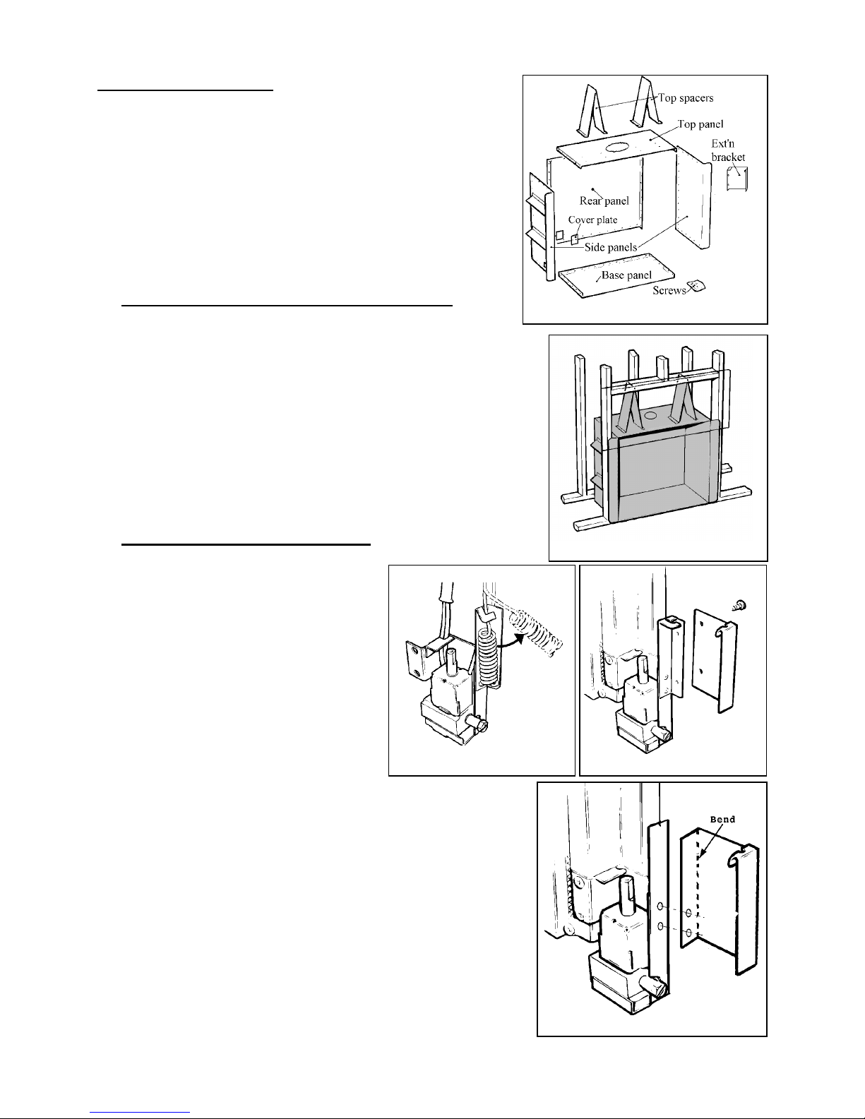
3. KIT COMPONENTS
The kit contains the following (fig. 3):
• 1 top panel.
• 1 rear pan el with spacers.
• 1 righ t side pan el with spacers
• 1 left side panel with spacers.
• 1 base panel.
• 2 top panel spacers.
• 1 inlet opening cover plate.
• 1 extension br a c ket f o r thermostat coil.
• 1 screw pack.
• 4. ASSEMB LE THE ZERO CLEARANCE KIT
• Assemble the rear, two sides, top and base panels, to form the zero
clearance box, using the screws provided, (see fig. 3)
• Fit the top spacers to the top panel using the screws provided(fig. 3).
• Fit the inlet opening cover plate to the rectangular opening which will not be
used for the gas inlet pipe.
• Secure the kit to the framing. Two fixing holes are provided in the base.
Alternatively the side flanges may be drilled and countersunk woodscrews
used.
• Fit the flue pipe through the hole in the top panel and secure to the appliance
vent connector as described in the appliance instructions.
• All wall and hearth finishes can now be applied.
• 5. INSTALLING THE APPLIANCE
• Detach the thermostat coil from securing
bracket at right side of appliance (see fig. 5).
• Fit the thermostat coil extension bracket to the
end of the existing bracket with the two screws
provided (fig. 6).
• Secure the thermostat coil to the tab at the top
right of the extension bracket.
• The unit can now be installed exactly as in a
masonry fireplace, see the appliance installation
guide.
If the appliance does not have a thermostat coil
bracket, work through the following steps
• Detach the thermostat coil from the securing clip at the right side of the
appliance.
• Bend thermostat extension bracket along perforated line through 90º (see
fig. 7).
• Fit the thermostat coil extension bracket to the two holes with the 2 screws
provided. (see fig. 7).
• Secure the thermostat coil to the tab at the top right of the extension
bracket.
• The unit can now be installed exactly as in a masonry fireplace, see the
appliance installation guide.
Fig.3
Fig.7
Fig. 4
Fig. 5
Fig. 6
 Loading...