

Page 1
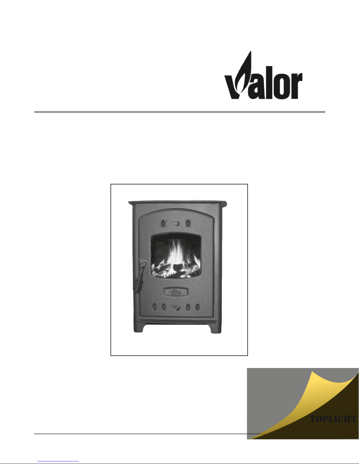
Willow
Multifuel Stove
Operating & Installation Manual
PLEASE RETAIN THESE INSTRUCTIONS FOR FUTURE REFERENCE
Willow Multifuel Stove
Tel.: +49 (0)40 - 88 9 0 100
www.toplicht.de
Schisausrüster
Page 2

2 Willow Multifuel Stove
WARNING
TO ALL MULTIFUEL USERS
PETROLEUM COKE
SOME OF WHOSE BRAND NAMES ARE
"CALCO", "PETROCOKE" OR "WONDERCO"
MUST NOT BE BURNED IN THIS APPLIANCE
TO USE THESE FUELS WILL INVALIDATE THE
APPLIANCE GUARANTEE
IF IN DOUBT CONTACT THE SOLID FUEL ASSOCIATION
TELEPHONE NUMBER 0800 600 000
www.solidfuel.co.uk
Page 3

Page
INTRODUCTION
Safety Notices 4
The Principle of the Fire 4
Check List 5
Technical Data 6
INSTALLATION
General Precautions 7
Handling 7
Hearth 7
Combustible Materials 7
Air For Combustion 7
Firebox Liner Panels 8
Removal of Throat Plate 8
Fitting the Optional Floor Fixing Kit 8
Fitting the Flue Outlet and Hotplate 9
Flues & Chimneys 9 - 12
Page
OPERATING INSTRUCTIONS
Air Inlet Controls 13
Multi-Purpose Operating Tool 13
Fire Door Glass 14
Adjusting the Door Hinges 14-15
Fuels 15
Lighting The Fire 16
Extended Burning 17
Over-Firing 17
Annual Maintenance 18
Part List 19-20
GUARANTEE 21
FINAL FACTORY CHECK LIST 22
Willow Multifuel Stove 3
CONTENTS
OPERATING & INSTALLATION INSTRUCTIONS
CONTENTS
Page 4

4 Willow Multifuel Stove
SAFETY
A fireguard conforming to BS 8423: 2002 should
be used in the presence of children and old/or
infirm people. If the appliance is used with the fire
door open, a spark guard conforming to BS 3248
should be fitted.
Do not use aerosol sprays or any other flame
near the appliance under fire.
Do not fit an extractor fan in the same room as
the appliance.
Fire cement is caustic, hand and eye protection
should always be worn, prolonged contact with
the skin should be avoided.
Valor will not be responsible for any
consequential or incidental loss or injury
however caused.
Before continuing any further with the installation
of this appliance please read the following guide to
manual handling.
•Always obtain assistance when lifting the
appliance.
•When lifting always keep your back
straight. Bend your legs not your back.
•Avoid twisting at the waist. It is better to
reposition your feet.
•Avoid upper body/top heavy bending. Do not
lean forwards or sideways when
handling the fire.
•Always grip with the palms of your hands.
Do not use fingertips for support.
•Always keep the stove as close to the body as
possible. This will minimise the cantilever
action.
•Use gloves to provide additional grip.
THE PRINCIPLE OF THE FIRE
Your Willow Multifuel Stove is built to the highest
standard of craftsmanship using the best materials
and the most modern equipment available.
It is a highly efficient and sophisticated piece of
machinery and when properly installed and
operated it should provide a lifetime of heating
satisfaction.
Safety is the most important consideration when
installing your fire. If not properly installed and
operated a house fire may result. Installation must
comply with the Building Regulations and conform
to all relevant fire safety standards.
Valor produce a variety of appliances ranging from
the traditional to the modern in style and
appearance, all bristling with "High Tech" features.
The fire doors are fitted with special high
temperature ceramic glass panels through which
the fire can be viewed.
The stove is lined with firebricks or heat reflective
panels which ensure complete combustion and
provide a good heat store to even out fluctuations in
burning.
An internal throat plate produces turbulence to
encourage secondary combustion and directs the
flue gas around the whole upper firebox before
allowing it to escape up the chimney.
Valor multifuel stoves are also fitted with an "air
wash" so called because it provides a curtain of
high speed preheated air behind the glass to help
keep it clean and to provide secondary air/over
draught.
The provision of two inlets on all multifuel stoves
gives a wide range of primary air/secondary air,
under draught/over draught combinations.
The optimum settings will only be established by
experience in firing the appliance, and will depend
on type of fuel, the position of the appliance in the
house, condition of chimney etc.
Page 5
Willow Multifuel Stove 5
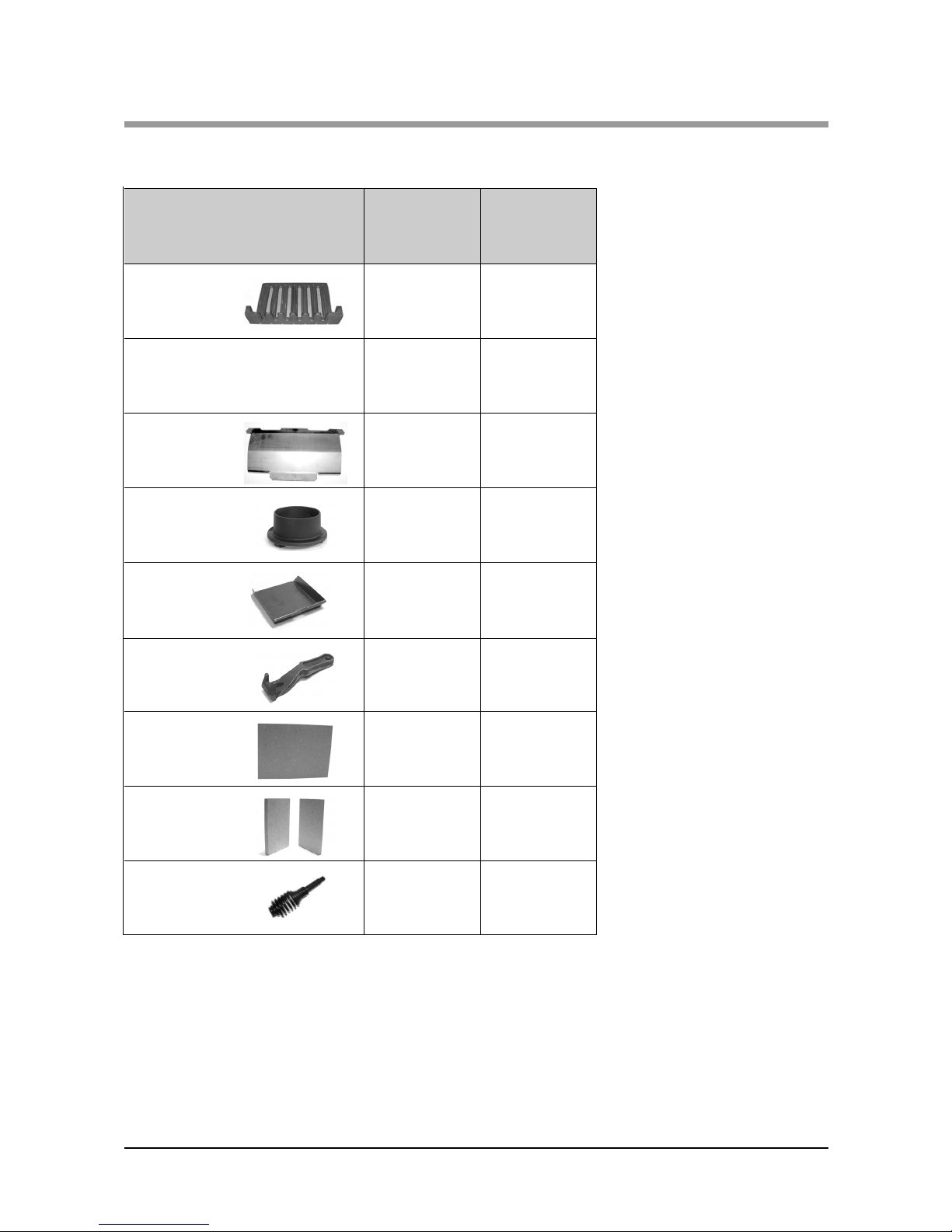
CHECK LIST
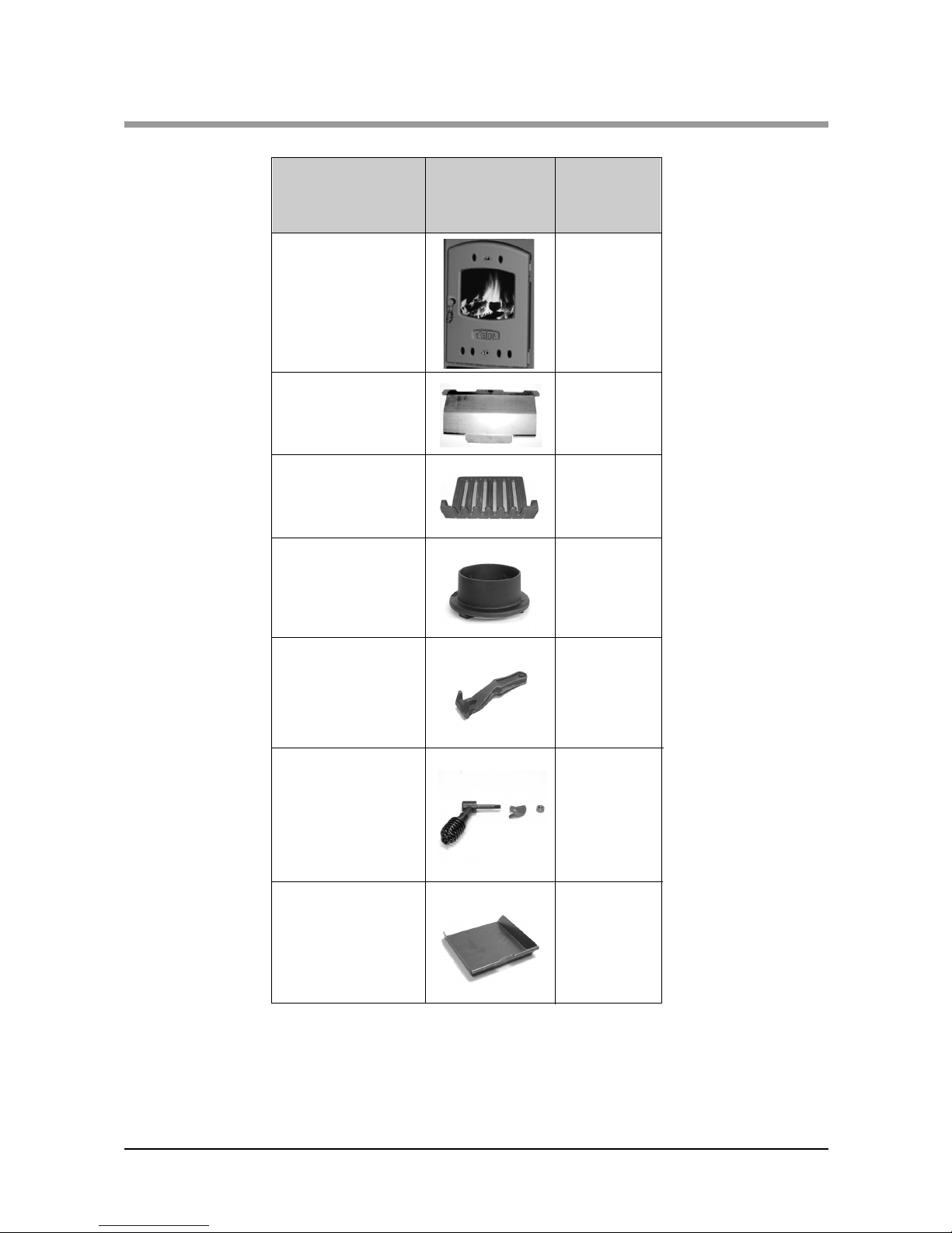
1. Fuel grate
1 AFS1087
Part Description
&Visual Aid
(not to scale)
Quantity Part No.
3. Throat
plate
1 AFS1086
4. Flue
spigot
1(4”) AFS009A
6. Ash pan
1 AFS1088
7.Operating
tool
1 AFS008
8. Rear
liners
1 AFS1093
9. Side liners
2 AFS1091
The model and Serial Number of your fire can be found stamped into the casing,
centrally just below the bottom edge of the fire door aperture.
Inside the appliance you should find the following:
2. Instructions
1
AFS1128
10.Fire door
handle
1
AFS205
Page 6

6 Willow Multifuel Stove
TECHNICAL DATA
Room Min/Max
Room heater only output (kW)
1 - 4 kW
TECHNICAL DATA
Willow
Multifuel
Height (mm) 455
Width (mm) 350
Depth (mm) 345
Height to centre of rear flue N/A
Depth from back to centre of flue 90
Flue diameter 102 (4”)
Weight Kg
Unpacked 31Kg
Packed 35 Kg
Page 7

Willow Multifuel Stove 7
INSTALLATION
GENERAL PRECAUTIONS
Note - All installations must conform to the
appropriate building regulations.
The Building Regulations for England and Wales
2000 ref Approved Document J 2002 edition
(issued by the DTLR).
The Building Standards (Scotland) (Consolidation)
Regulations.
Detailed recommendations for installation of
appliances, chimneys and flues are outlined in the
current issue of the following British Standards:BS6461, BS8303 and BS4543.
Any Manufacturer's Instructions must not be
taken as overriding statutory requirements.
During installation ensure that adequate
precautions are taken to avoid unnecessary risk to
yourself or any householder. In particular the
danger from the caustic nature of the fire cement
should be avoided by using these accepted
methods:
•Wear gloves when handling fire cement.
•Wear goggles when chiselling or looking up
chimneys.
Make sure that Building Regulations are adhered to
during installation along with any local by-laws.
In the case of heating systems make sure that the
pipe work is correctly bonded to ensure electrical
earthing.
HANDLING
By the time you read this you will appreciate the
weight of the appliance. The Safety and handling
guidelines as set out on page 4 of this manual
should be followed.
To make movement easier internal fittings, grates,
firebox liners, flue outlets, hot plate, throat plate,
etc., can be removed.
Care should be taken to make sure that the hinges
are not damaged during installation.
HEARTH
The fire should be installed to stand on a
constructional hearth of non-combustible materials
not less than 125mm (5'') thick conforming to
Building Regulations. Dimensions of the hearth
should project at least 300mm (12'') forward of the
front of the appliance and 150mm (6'') at the sides.
The surface of the hearth should be free of
combustible materials. In most buildings with solid
concrete floors the requirement will be met by the
floor itself, but mark the perimeter of the hearth to
ensure floor coverings are kept well away or use
different levels to mark the hearth perimeter.
COMBUSTIBLE MATERIALS
A gap of at least 450mm (18'') should be allowed
between the appliance and any combustible
materials including furnishings. Adjacent walls
should be of suitable non-combustible
construction, preferably brickwork. In large
fireplaces take care that any supporting beam is
protected by a 13mm (0.5'') sheet of
Masterboard/Supalux spaced 13mm (0.5'') off the
surface with strips of non-combustible material
- not wood.
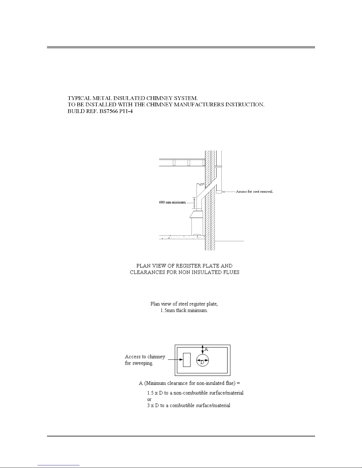
Make sure that there is a gap between an
uninsulated flue system and any combustible
material. This gap must be at least 3 x the outside
diameter of the flue pipe, or 1.5 x the flue diameter
to non combustible surfaces. see illustration p12.
AIR FOR COMBUSTION
There must always be a permanent means of
providing air for combustion into the room in
which the fire is installed. A permanent vent with a
total free area of at least 550mm
2
for every kW
rated output above 5kw should be connected
directly to the outside air or to an adjacent room
which itself has a permanent vent of the same size
direct to the outside air. The fitting of an extractor
fan to either of these rooms is not recommended.
Page 8
8 Willow Multifuel Stove
INSTALLATION
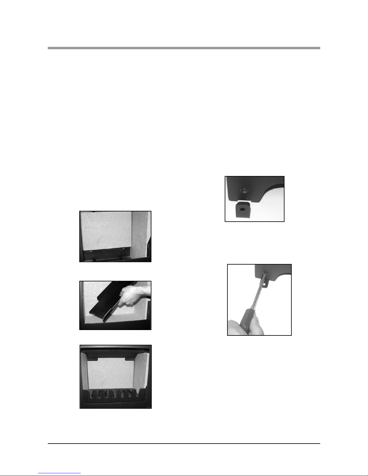
FIREBOX LINER PANELS
The Willow multifuel stove use firebox liner panels
to the sides and back. The throat plate sits on top of
the side and rear panels. These should come fitted
to your fire, if however they are not proceed as
follows to fit them.
•Set the small liner into the back of the fire.
•Insert side liner panels into each side of the fire.
•Fit the throat plate with the single bend and two
cut outs to the front facing up. The projecting lugs
sit on top of the side liners. The long centre tab on
the back edge rests on the rear liners. The shorter
turn-down tabs against the vertical face.
Note: Neither the rear firebox liners nor the side
firebox liners are "handed", both faces are
suitable for direct contact with the fire. Cracking
of lining panels does not effect efficiency.
Fig. 1 Liners inserted into the Willow.
Fig. 2 (Inserting throat plate)
Fig. 3 Liners, throat plate and grate in
the Willow.
REMOVAL OF THE THROAT PLATE
Blocked chimneys cause dangerous fumes to
escape. Remove throat plate at least monthly to
clean. Keep chimney and flue ways clear.
FITTING THE OPTIONAL FLOOR
FIXING KIT
Once the stove is in the correct position it is
recommended that the fire is fixed to the floor for
safety purposes:
You will need a No. 2 pozi drive screw driver to
carry out this operation. Place the brackets each
side of the appliance.
Fig. 4 Lining up the bracket
Slide the small threaded hole underneath the gap
(as shown above) and turn inside so the both holes
match the pre-drilled one. Repeat for the other side.
Fig. 5 Inserting and tightening the screws.
When both are in place, tighten the screws until
they are firmly inserted.
Then proceed to drill your hearth and insert and
anchor bolt or similar fixing (Not supplied in kit)
and bolt down the brackets once the appliance is in
place. For further instructions please consult the
floor fixing instructions attached to the kit.
Page 9

Willow Multifuel Stove 9
INSTALLATION
FITTING THE FLUE OUTLET
The flue outlet spigot is found inside the appliance.
It is removed by turning clockwise.
Smear a very thin layer of fire cement on the faces
of the flue outlet. Fit the outlet to the appliance in
the desired position.
Lock into place by rotating anti-clockwise and
tighten by tapping with a block of wood and mallet
from the inside of the appliance.
Place appliance on the hearth and make sure that it
is level and does not rock. Connect the chimney
ensuring all joints are sealed with fire cement.
Fig. 6 Flue and Spigot Fitting
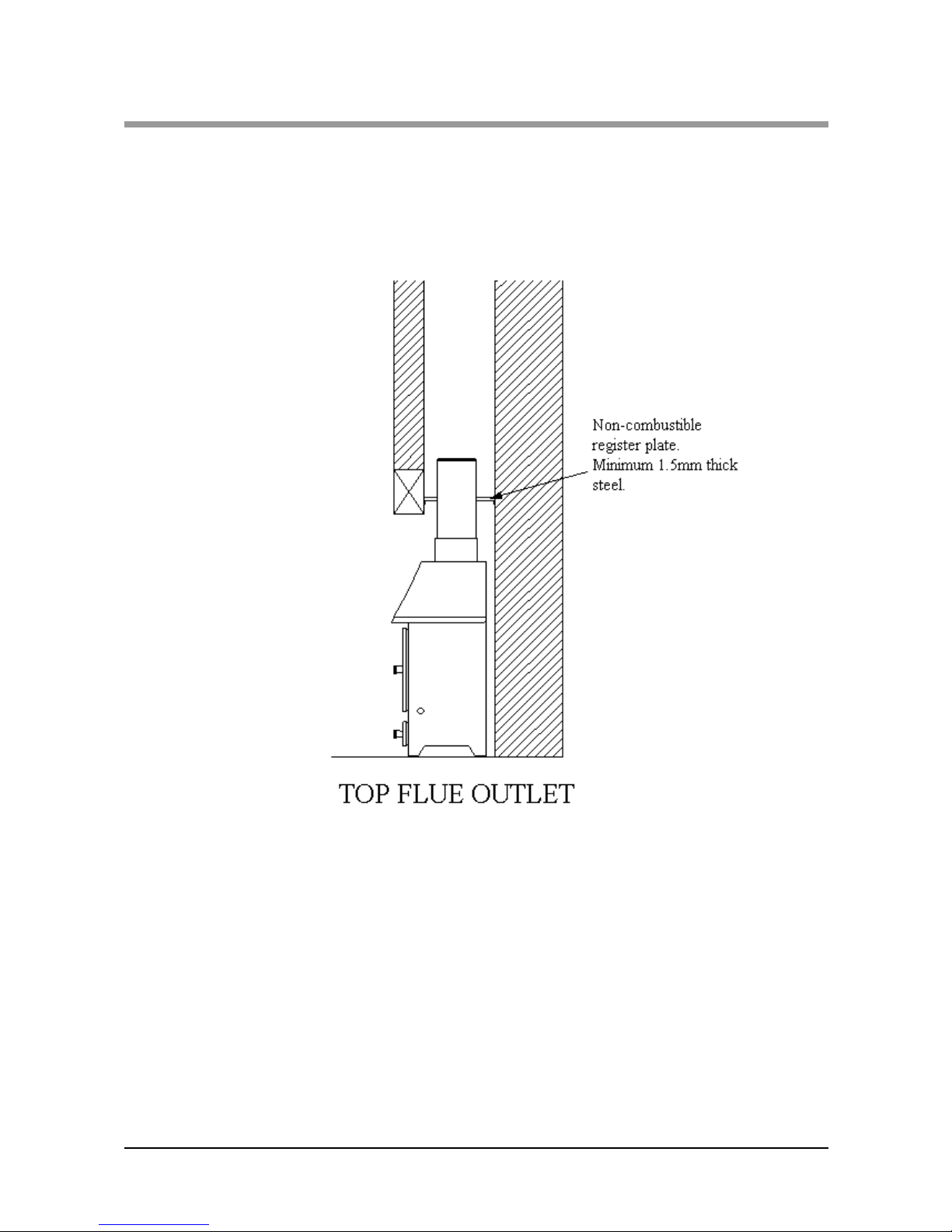
FLUES AND CHIMNEYS
Please remember that chimney draught is
dependent on four main factors:
•Flue gas temperature.
•Flue height.
•Flue size.
•Flue terminal.
The stove must be connected to a suitable and
efficient flue that provides a good up draught to
safely take the products of combustion (fumes)
from the stove outlet to the outside air. To ensure a
good updraught it is important that the flue gases
are kept warm and that the flue size suits the stove.
The termination of the outlet at the top of the flue
also needs to comply with the Building
Regulations. The minimum effective height of the
flue must be at least 4.5 metres from the top of the
stove to the top of the flue outlet. When warm the
flue draught should be between 0.1 and 0.2 mb.
A chimney may comply with the regulations but
still be subject to down draught and similar
problems. A chimney terminating above the ridge
level is generally less likely to suffer such
problems.
If a new chimney is being provided it should fully
comply with the relevant Building Regulations that
specify the requirements for solid fuel burning
installations. Suitable types of chimney include the
following.
Masonry chimney built with clay or concrete
liners, or a chimney block system meeting Building
Regulations. These types of chimney should be
installed in accordance with the Building
Regulations and BS 6461: Part 1.See page 12 for a
typical installation diagram.
Factory made insulated chimney complying
with BS 4543: Part 2 (often called "Class 1
prefabricated metal chimney"). These types of
chimney should be installed in accordance with the
Building Regulations and BS 7566: Parts 1 to 4.
See page 12 for a typical installation diagram.
*NOTE
THE FLUE PIPE MUST BE FITTED INSIDE TH E OUTLET SPIGO T
FAILURE TO DO SO COULD RESULT IN THE SPILLAGE OF
CONDENSATION ECT. RUNNING DOWN THE FLUE.
Page 10

10 Willow Multifuel Stove
INSTALLATION
Due to the gradual introduction of European
Chimney Standards chimneys will be specified
according to their performance designation as
defined in BS EN 1443 that covers the General
Requirements for chimneys. The minimum
performance designation required for use with solid
fuel burning stoves is T450 N2 S D3.
The flue and chimney installation must be carefully
checked by a competent person before fitting the
stove to ensure it is suitable and will work safely.
If the chimney is old (ie built of brick or stone
without a liner) or being opened up for reuse
additional checks and smoke testing as described in
Appendix E of the Approved Document J 2002
Edition should also be carried out to ensure the flue
and chimney are in good operating condition.
Unless the existing flue is in good condition with
suitable access for collection and removal of debris.
If the flue size is more than 225mm (9 inches)
diameter or 200 x 200mm square, a suitable lining of
150mm (6 inches) diameter should be fitted, or if the
flue length is over 5.5 metres one size larger than the
appliance outlet should be fitted. This should be a
double skin stainless steel flexible flue liner that is
independently certified for use with solid fuel.
Details of suitable linings for use with solid fuel are
given in the Official HETAS guide that can be
viewed on their website at www.hetas.co.uk
It is also important that suitable flue pipe
complying with the Building Regulations is used to
connect the stove to the flue in the chimney and that
suitable access is provided into the flue for regular
inspection and sweeping of the flueways.
The installer should comply with the Building
Regulation requirements in respect of providing a
Notice Plate giving details on the chimney, flue
lining, hearth and fireplace installation. Approved
Document J of the Building Regulations for
England and Wales is available from The
Stationery Bookshops and can also be
viewed at the ODPM website at
www.safety.odpm.gov.uk/bregs/brads.htm
Details on the relevant Building Regulations and
BS British Standards are given in the "General
Precautions" section of these instructions.
Chimneys should be as straight as possible.
Horizontal runs should be avoided except where
the rear outlet of the appliance is used, in which
case the horizontal section should not exceed
150mm (6'') in length. See page 11 for a typical
installation diagram.
If the fire appears to be working hard but produces
very little output to the room it is likely that
excessive draw is present in the chimney, and that
heat is being sucked out of the appliance and up the
chimney. If this is the case we recommend the
fitting of a draught stabiliser in preference to a flue
damper, in the interest of safety and efficiency.
We do not recommend the use of a damper when
burning solid fuel.
FOR ALL APPLIANCES
Access for cleaning the flue should be incorporated
in the system other than through the appliance (e.g.
a soot door or access through register plate).
Purpose-made soot doors and inspection lengths
are available from manufacturers of all systems.
Ensure that the whole length of the flue can be
reached from the soot door.
Note: if the appliance is fitted with a draught
stabiliser or if one is fitted to the flue pipe or
chimney in the same room as the appliance, then
the permanent air entry opening (or openings)
should be increased by 300mm
2
for each kW of
rated output.
For advice on flues and chimneys contact;
NACE (National Association of Chimney
Engineer): telephone 0800 0924019
www.nace.org.uk
or
NACS (National Association of Chimney
Sweeps): telephone 01785 811732
www.chimneyworks.co.uk
Page 11
Willow Multifuel Stove 11
INSTALLATION
Page 12
12 Willow Multifuel Stove
INSTALLATION
TYPICAL METAL
INSULATED CHIMNEY SYSTEM
TO BE INSTALLED TO THE CHIMNEY MANUFACTURERS INSTRUCTIONS IN COMPLIANCE
WITH BUILDING REGULATIONS AND BS7566 PTS 1-4
Page 13
Willow Multifuel Stove 13
OPERATING
AIR INLET CONTROLS
The Willow multifuel stoves have two air inlets; the
upper set of holes:
•The air wash system (so called because its
pre-heated high speed air washes across the inner
face of the door glass, keeping it clear), which
provides over draught, and
•The lower set of holes; the primary air inlet
providing under draught to the base of the fire
chamber through controls on the bottom of the
stove door.
PRIMARY AIR FOR MULTIFUEL
Air enters the appliance through the control on the
bottom of the fire door. The Valor Willow has a
single control knob which slides left to right.
Sliding the knob to the right will increase the
amount of air intake to the stove. To decrease push
knob to the left.
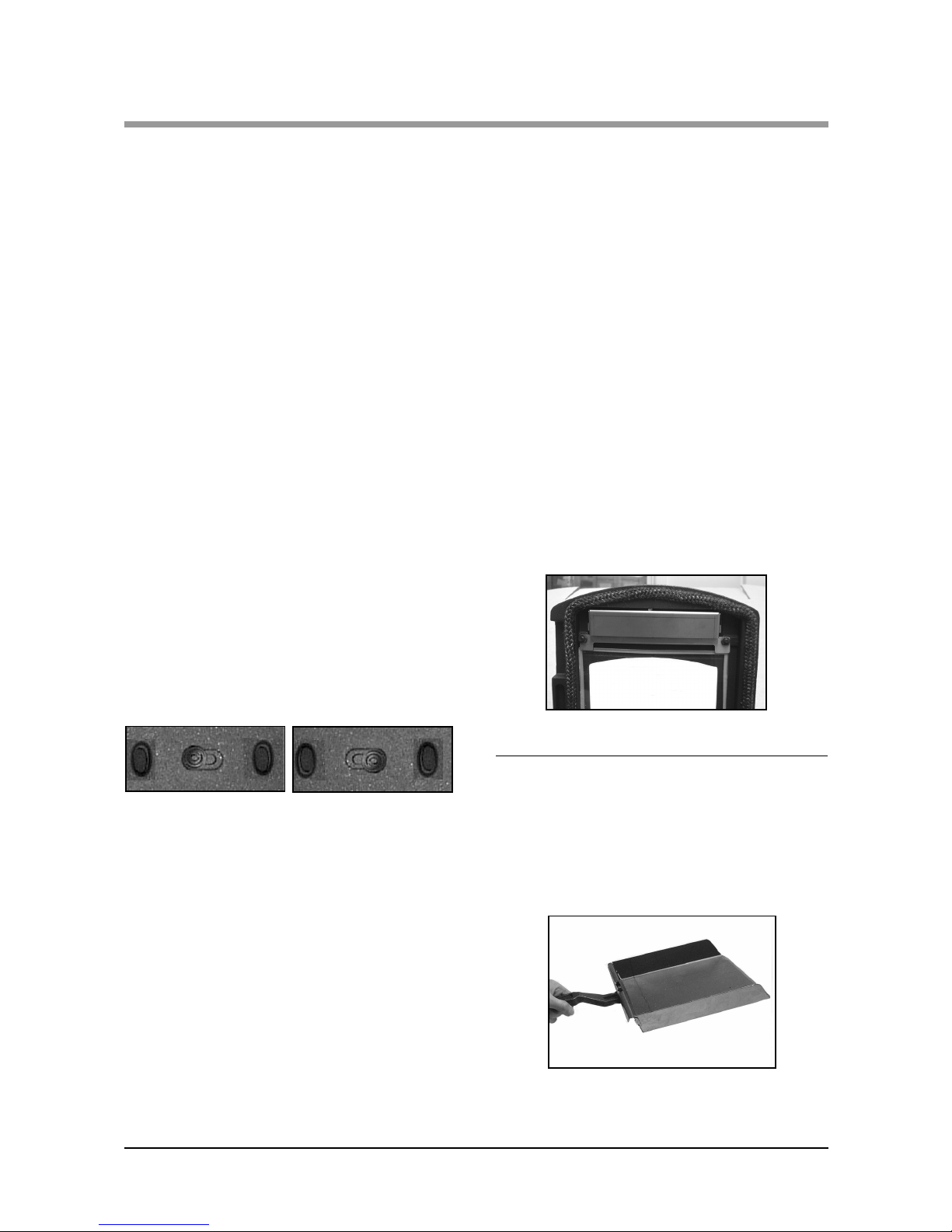
AIRWASH SYSTEM
The air wash has an internal sliding plate with slots,
housed in a cover plate, and is located above the fire
door. Sliding the control knob to the right as far as it
will go achieves the fully open position. Sliding it to
the left will shut off the air inlet slots As shown below.
Fig. 7 Fully Closed Fig. 8 Fully Open
DISASSEMBLE AIRWASH
The Valor Willow air wash may be disassembled
for cleaning or adjustment. To achieve this, the
following procedure should be followed:
This should only be carried out when the fire is cold
and unlit.
•Remove the glass by unscrewing the top and
bottom nuts (See Fig 9) that secure the glass.
•Carefully remove the glass and lift cover off.
Unscrew the airwash spring knob from the sliding
plate.
•Remove assembly from the appliance.
•Clean and/or adjust.
•Refit using reverse procedure.
Fig. 9
MULTI - PURPOSE OPERATING
TOOL
Your Willow stove comes with a multi-purpose tool
which is used to remove the ash pan (Fig. 10)
Fig. 10
Page 14
14 Willow Multifuel Stove
OPERATING INSTRUCTIONS
FIRE DOOR GLASS
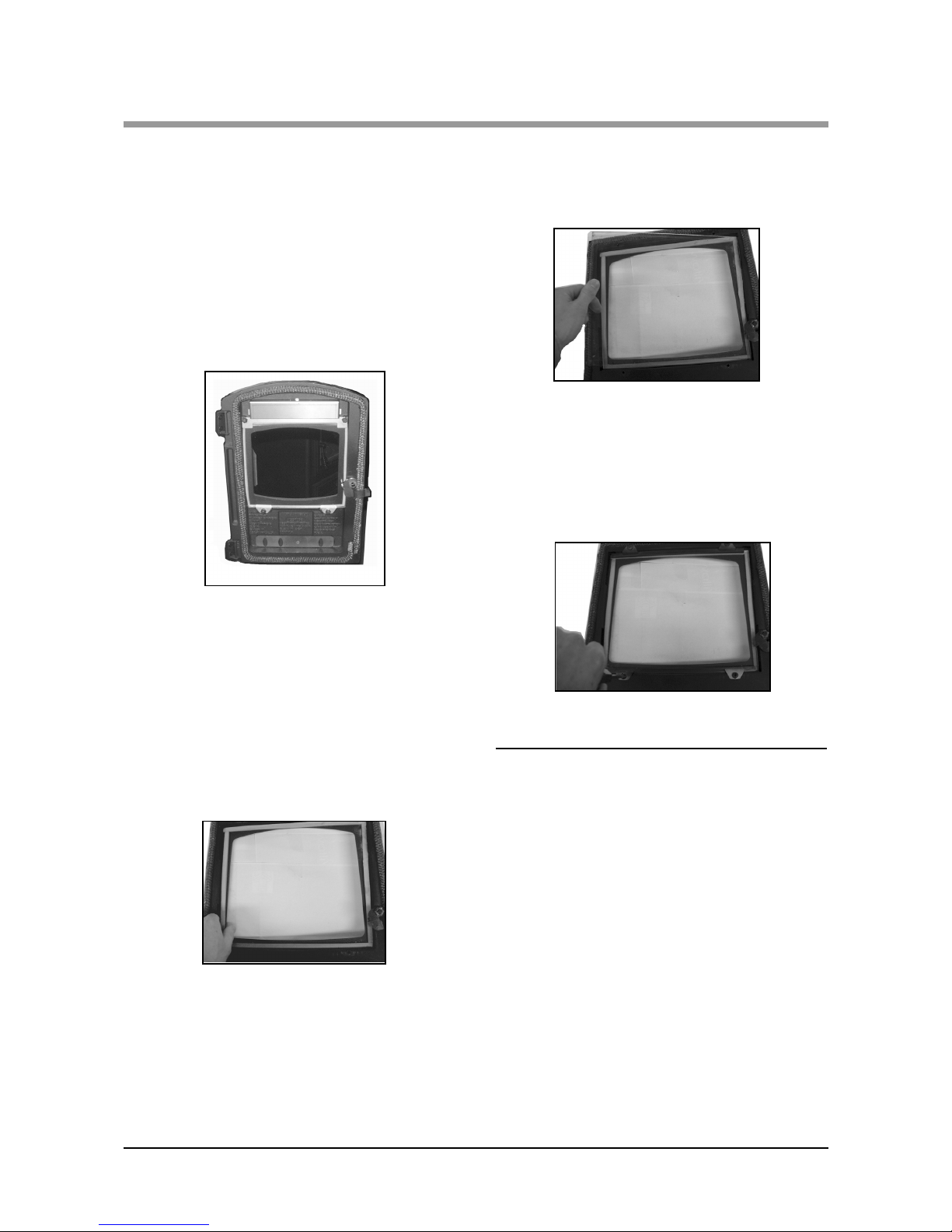
In the event of the door glass being broken it can
easily be replaced:
•The door should be lifted off the hinges so that
the above operations can be carried out on a
workbench or similar level surface. This should be
done when the appliance is cold (fig.11)
Fig. 11 removal of stove door
•Unscrew the four nuts, on the inside of the door.
•Remove the upper airwash cover and the two
cover glass clips.
•Carefully remove any pieces of broken glass, and
sealing gasket wearing suitable gloves.
REFIT NEW GASKET
•The fitting of new gasket is shown below (fig.12a)
Fig. 12a fitting new door gasket
•Re-seat the new glass, ensuring the sealing gasket
is flat and in contact with the glass.
Fig. 12b fitting new glass
•Replace the two lower retaining clips and nuts.
•Replace the upper airwash cover and nuts. Do not
over-tighten the nuts as damage may occur to the
glass (fig.12c)
Fig. 12c tightening nuts
ADJUSTING THE DOOR HINGES
Once the appliance has been under fire for a period
of time the fire door may appear to have moved out
of alignment with relation to the door aperture or
catch. This is quite normal and due to the settling of
the casing.
The fire door can be re-aligned by the user as
follows:
•When the appliance is cold, open the fire door so
that it is at right angles to the front of the fire.
•Lift the fire door up off its hinges.
Page 15
Willow Multifuel Stove 15
OPERATING INSTRUCTIONS
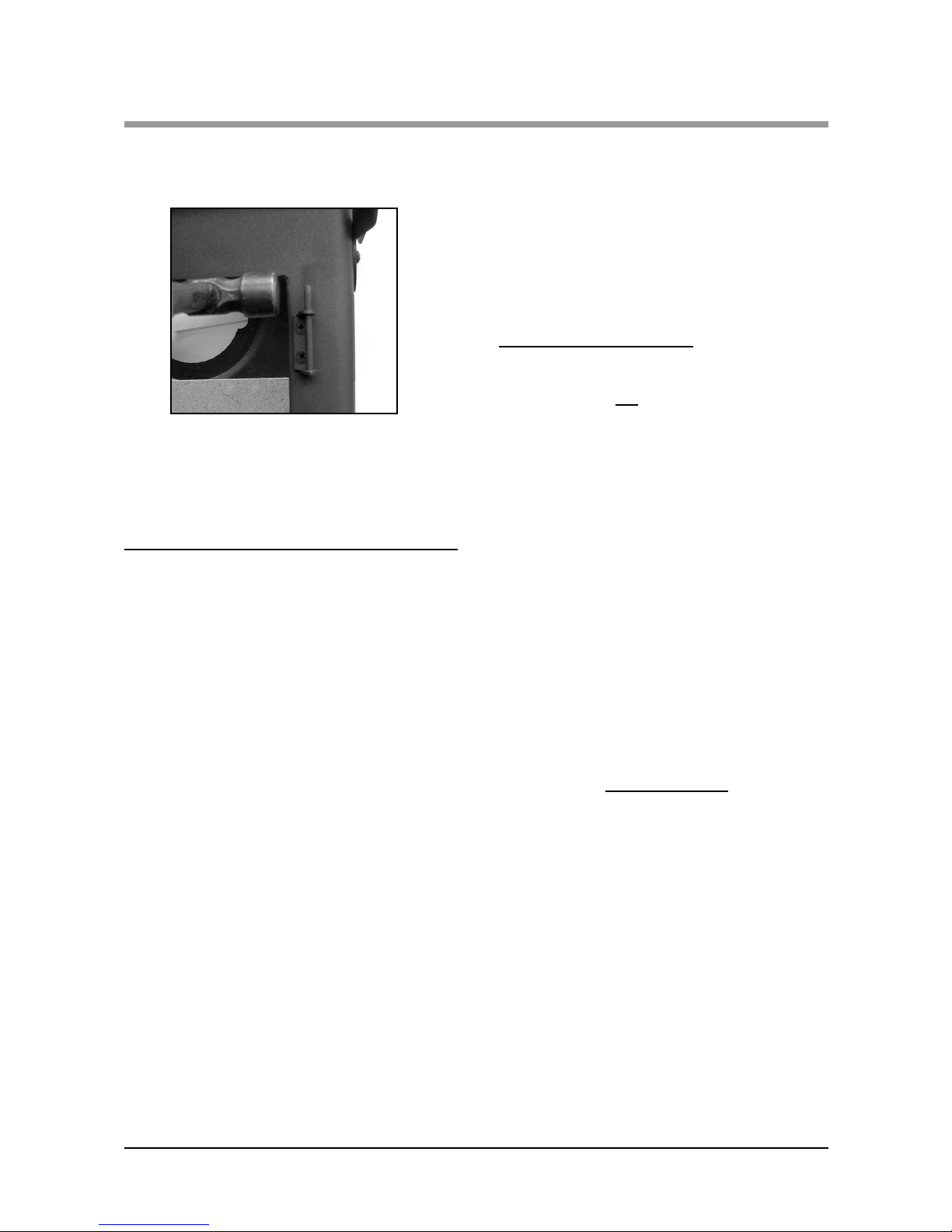
•Gently tap the hinge pins in a direction to
compensate for the misalignment (Fig. 13)
Fig. 13 tapping door hinges
•Refit the door and check to ensure it now
sits square to the body; if not repeat above
steps.
FUEL TYPES
Wood- Any type of wood is suitable provided it is
well seasoned and has a moisture content below
20%. This usually implies that the timber has been
suitably stored to allow moisture to evaporate for at
least nine months in the case of soft woods, and at
least eighteen months in the case of hard wood. We
recommend that for general burning, wood should
be split into logs of no more than 130mm (5")
diameter.
Larger logs can be used for overnight burning.
WARNING wet wood must not be used as this will
greatly contribute to the creation of tar and creosote
which may, in extreme cases, run down the
chimney in liquid form. This will seriously damage
both the chimney and the appliance, and increase
the risk of chimney fire.
Note: If you have sticky tar inside the appliance or
chimney your wood is 'Green' or too wet.
Recommended Reading:
"Wood as Fuel" available from the Forestry
Commission.
Peat- Can be used in turf or briquette form, but
again the moisture content must be low.
Paper- paper will burn successfully. Burn dry
paper only or chimney damage will occur.
NEVER BURN PLASTICS OR WASTE IN
YOUR STOVE.
Coal for Multifuel only - Household coal
produces a large amount of ash and smoke and
chimney will require frequent cleaning. Therefore
soft house coal is not
recommended.
Recommended fuels are as follows:
The Hetas Ltd, "Three tick" appliance approval
only covers the use of the following fuels in this
appliance;Phurnacite, Phurnacite Plus, Centurion,
Maxibrite,Extracite,Pureheat, Blazebrite, Taybrite,
Sunbrite (double/singles), Anthracite (large nuts),
and Welsh Dry Steam Coal (large/small nuts).
Approval does not cover the use of other fuels
either alone or mixed with a suitable fuel listed
above, nor does it cover instructions for use of
other fuels. For latest details please refer to Hetas
website www.hetas.co.uk.
Do not use Homefire (six sided) and smaller sizes
than Stovesse, e.g. Beans,Peas,Grains.
Do not use petroleum based solid products such
as Calco or Petrocoke.
To do so will INV
ALIDATE the appliance
guarantee.
Page 16

16 Willow Multifuel Stove
OPERATING INSTRUCTIONS
LIGHTING THE FIRE
Prior to lighting the fire for the first time check
with the installer that:
•Installation and all building work is complete.
•The chimney is sound and has been swept and is
free from obstruction.
•Adequate provision for combustion air has
been made, i.e. a permanent vent of at least
550mm² per kW of rated output above 5 kW,
is fitted in the room in which the appliance
is installed.
•That Building Regulations and any local
by-laws have been followed during installation
(see installation instructions).
•All firebox liner panels are in place.
•Throat plate is in place.
•Where add in boilers are fitted ensure that the
system is full of water and vented, and
precautions have been taken to prevent corrosion
(see installation Instructions).
•That the chimney draw has been checked and is
within specification. With the chimney warm the
draught should be between 1 - 2mm water gauge
(0.1 - 0.2mbar).
WARNING: An over drawing chimney can cause
over-firing resulting in damage to the appliance.
ENSURE THAT YOU HAVE READ &
UNDERSTOOD THESE INSTRUCTIONS
BEFORE LIGHTING THE FIRE.
ALWAYS WEAR SUITABLE PROTECTIVE
FIRE GLOVES WHEN REFUELLING YOUR
STOVE.
SOLID FUEL BURNING - Multifuel Stoves
•Ensure that the multifuel grate and ash pan are in
position and the fire doors are closed.
•Set the air wash to one quarter open position.
•Set the primary inlet to the fully open position
•Light in the normal manner with paper and
kindling, or use a fire lighter.
•If using a gas poker be sure to remove it
immediately the fire is alight.
•When the fire is well alight regulate the burning
rate by adjusting the setting on the primary air
inlet control.
•The air wash can be opened sufficiently to keep
the door glass clean.
BURNING WOOD
•Set air wash to fully open position
•Proceed as for solid fuel but note the fire will burn
up and become established more quickly.
MIXED FUELS
•As per coal but allow additional secondary air.
•The primary air inlet can be closed and burning
regulated by means of the air wash above the door.
ANTHRACITE
Anthracite is more difficult to keep in for long
periods, consequently more care in setting the
controls and some familiarisation is necessary
when burning anthracite.
Use the smallest size fuel (Stovesse or Small Nuts).
Proceed as for manufactured smokeless fuel. Leave
the air inlet control open about a quarter or less.
Note: The high temperature paint acquires
durability by being "cured" during the initial
firings of the appliance will give off fumes which
are non-toxic, but which certain persons may find
have an unpleasant or irritant effect. Ensure that
the area is well ventilated during this time.
Page 17

Willow Multifuel Stove 17
OPERATING INSTRUCTIONS
EXTENDED BURNING
The appliance will burn for an extended period
provided:
•Sufficient fuel is placed in the firebox.
•The controls are set correctly.
•Excess draught is not present in the chimney.
•Fire door is closed.
•If the fire goes out with unburnt fuel left in
the firebox increase the air opening slightly,
and vice versa.
In the morning
•Open the air control fully until embers begin
to glow brightly and place pieces of fuel on
the fire until it is well established.
WARNING: When wood is burnt slowly in a
closed appliance it produces moisture and tar,
which will create condensation and deposits in the
chimney. This effect can be minimised by burning
hard for a short period, about 20 minutes, twice a
day. It is usually convenient to do this morning and
night.
Note: To avoid chimney problems your fire should
not be burnt slowly for longer than 12 hours
without a period of fast burning.
WARNING: Properly installed, with a suitable
flue and chimney and operated and maintained
this appliance will not emit fumes into the
dwelling. Occasional fumes from the de-ashing
and re-fuelling may occur. However, persistent
fume emission is potentially dangerous and must
be investigated by a Hetas registered installer.
Stop using the appliance if you smell fumes or
see smoke escaping.
If fume emission does persist, the following
immediate actions should be taken.
•Open doors and windows to ventilate room.
•Let the fire die or extinguish and safely
dispose of fuel from the appliance.
•Check for flue or chimney blockage, and
clean if required.
Seek expert advice from your HETAS registered
installer. Do not attempt to re-light the fire until the
cause of the fume emission has been identified and
corrected
ASH REMOVAL
The appliance will require ash to be removed
periodically but an ash bed of approximately 20mm
(3/4'') should be maintained. Ash may be removed
with a small shovel whilst the fire is still lit by
raking the embers of a low fire to one side of the
fire box and carefully removing the ash, then
repeating the procedure for the other side. Care
must be taken not to risk burning of hands or
household objects from falling embers.
DE ASHING
It is necessary to maintain an ash layer on the upper
surface of the grate bars, in order to protect them,
so de-ashing should cease as soon as the first red
embers drop into the ash pan. Further de-ashing
will cause heat build-up under the grate, which will
considerably shorten its life.
TO EMPTY THE ASH PAN Open the fire
doors. Fit the fork end of the operating tool into the
ash pan and remove from the ash pit chamber.
WARNING: The ash can be very hot. Empty only
to a metal container. Even if the ash appears cold,
red-hot pieces of ash may be concealed and could
easily start a fire or cause an injury.
CLINKER
The formation of clinker suggests that the unit is
being over-fired. Any clinker forming on the grate
should be removed when cold.
OVER-FIRING
Do not over fire your appliance. Using flammable
liquids or too much wood or firing the stove at
maximum for prolonged periods may result in overfiring. If the chimney connector or casing glows red
the appliance is being over-fired. If this occurs
immediately close all air inlets to the appliance to
reduce the air supply to the fire. Should a chimney
fire occur immediately close the appliance down.
Get everyone out of the house and call the fire
brigade. A chimney fire may cause structural
damage to the chimney. Do not use the appliance
until the chimney and connector have been
inspected and any damaged parts have been repaired
or replaced. This should be done by a competent
person such as a HETAS registered engineer.
Page 18

18 Willow Multifuel Stove
OPERATING INSTRUCTIONS
CLEANING
Important; Under some circumstances soot can quickly
build up on the throat plate and adjacent areas. The
throat plate should be removed and checked monthly,
and any debris stripped off. Similarly, clean the upper
surface of the firebox.
ANNUAL MAINTENANCE
It is important that your fire is regularly serviced in
accordance with these instructions. This should be
carried out at least annually by a qualified person and
should consist of the following.
Remove the firebricks lining and throat plate, inspect all
gasketing on doors, glass etc., and re-order any items
that may need replacing, from your Valor dealer. With
a wire brush clean inside the appliance paying attention
to the small inlet holes on the fire door.
Sweep the chimney and confirm that it is sound.
Examine all joints in the flue pipe etc., and re-seal if
necessary. Reassemble and leave with the air inlet and
air wash control about half way open. This will allow a
free flow of air through the appliance thus preventing
moisture and condensation from building up inside the
fire and chimney.
CHIMNEY SWEEPING
Sweeping should be carried out with an appropriate
sized bristle brush and rods to suit chimney size and
type. As with all appliances regular sweeping of the flue
is essential to avoid the danger of blockage and the
escape of poisonous fumes. Access for cleaning should
also be incorporated in the chimney (e.g. soot door or
access through register plate).
Any existing chimney should be swept prior to
installation of the appliance, and swept again a second
time within one month of regular use after installation
to establish frequency of sweeping required. This
should be done by a competent person such as a NACS
chimney engineer who will provide a Certificate of
Chimney Sweeping.
The whole flue way including the outlet must be swept
at least twice per burning season. It is important that the
flue ways, flue pipe and chimney be cleaned prior to
lighting the fire after a prolonged shut-down period.
DOOR GLASS
The door glass should remain clear during normal
daytime burning. However under certain conditions-such
as burning at a low rate with damp wood, or overnight
burning, the glass may become somewhat blackened. To
remedy this, operate the appliance at a fast rate.
Alternatively when the stove is cold open the door and
clean the inside face of the glass with a damp cloth or
with glass cleaner (available from fire stockists). Apiece
of cloth moistened with vinegar and dipped in wood ash
- not coal ash - will provide a good soft scourer to
remove the soot without scratching the glass.
OUTER FINISH
The outside finish of the appliance is a durable high
temperature paint. It is best cleaned by brushing down
with a clean shoe brush. Do not allow moisture to remain
on the appliance whilst cold or surface rust may form.
The high temperature paint should not require attention
for some time, depending on use. The hotter the fire
burns the sooner repainting will be necessary. Aerosol
tins of paint are available for complete refurbishing.
Before repainting make sure that the fire is out and is
cold.
•Remove the door glass.
•Lightly wire brush, or rub with wire wool, the body of
the appliance to remove any loose paint
powder.
•Mask or remove items such as brass work.
•Any adjacent brickwork, mantelpiece, hearth, etc.,
should be carefully masked for quite a distance around
the appliance. (this precaution is to prevent
discolouration of the surrounding brickwork,
wallpaper etc).
Re-spray in a well-ventilated area - avoid breathing
the vapour. Refer to safety instructions on paint
cans.
•When the paint is dry refit door glass and any other
parts previously removed.
•Leave the appliance for eight hours before-lighting.
•Burn slowly for the first four hours, then build up heat
gradually to cure the paint.
Note: Use only genuine Valor touch-up spray as some
paints interact. This could ruin the finish and
invalidate the guarantee.
Page 19
Willow Multifuel Stoves 19
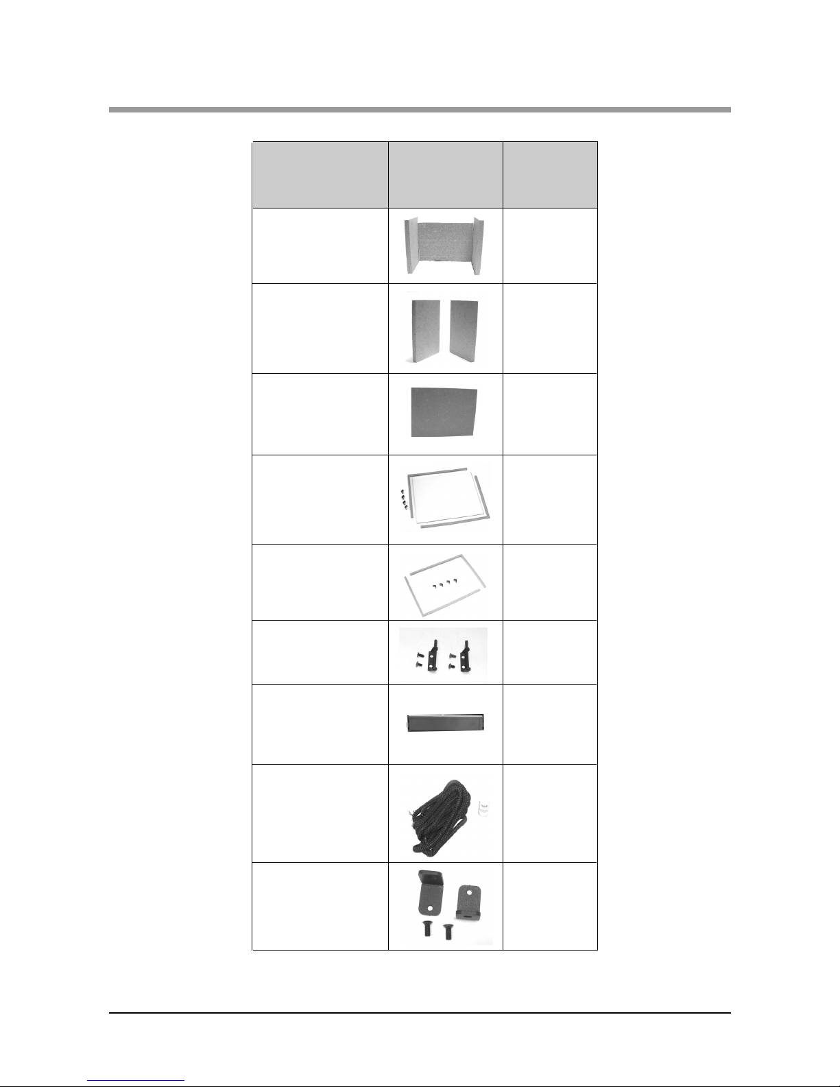
SPARE PARTS
AFS1086
AFS1087
AFS008
AFS1088
AFS009A
2. Throat Plate
3. Fuel Grate
5. Operating Tool
7. Ashpan
4. Flue Spigot
Part Description
Visual Aid
(not to scale)
Willow
Part No.
6. Fire Door
Locking Assembly
AFS204
1. Main Door
Assembly Complete
with Handle,Glass,
Gaskets,Clips and
Seal.
AFS1098
Page 20
20 Willow Multifuel Stoves
SPARE PARTS
8. Liner Set
AFS1089
AFS1091
AFS1093
AFS1095
AFS1096
AFS047
AFS1097
9. Side Liner
10. Back Liner Set
11. Glass
Replacement Kit
Complete with
Gasket
12. Glass Clips with
Gasket
13. Hinge kit
Comprises 2 Hinges
& 4 Fixings Per Set.
14. Willow Airwash
Part Description
Visual Aid
(not to scale)
Willow
Part No.
15. Fire Door Rope
Kit Complete with
Door Rope Glue.
AFS048
16. Optional Floor
Fixing Kit.
AFS1135
Page 21

Willow Multifuel Stove 21
GUARANTEE
Your Valor Willow stove carries a guarantee against defects of manufacture and faulty
workmanship for a period of one year from the date of purchase. This does not apply to items
which would be subject to fair wear or tear. Firebox liner panels, throat plate, door rope, door
glass and gaskets are not covered by the guarantee. However, should you have any problems with
your appliance please contact your Valor stockist who will have the knowledge and facilities to
help you.
Valor will not be responsible for any consequential or incidental loss, damage, or injury
however caused.
USE OF SPARE PARTS OTHER THAN THOSE SUPPLIED BY VALOR WILL
INVALIDATE THE APPLIANCE WARRANTY.
All Guarantee periods commence on the date of purchase and are non-transferable.
Our Guarantee is offered as an addition to your statutory rights.
Guarantee applicable to original purchaser only. Not transferable.
This installation and operating manual gives sufficient details to enable the appliance to be
installed and maintained. If further information is required, our Valor Technical Helpline will be
pleased to help.
Please telephone 08706 061 065 (local rates apply)
If you are calling from the Republic of Ireland please phone 0044 08706 061 065
When you contact them, they will need to know :
1. Your name, address, post code and telephone number.
2. Date of purchase and supplier details
3. Name of installer
4. Stove serial number
5. Clear and concise details of the fault.
Please complete the following for you own records
Date of Purchase.............................Model.................. Serial Number.................................
Name and address of supplier.........................................................................................................
.........................................................................................................................................................
.........................................................................................................................................................
Name and address of Installer.........................................................................................................
.........................................................................................................................................................
.........................................................................................................................................................
Page 22
FINAL FACTORY CHECK LIST
QUALITY
FINISH
PART S
FLUE OUTLET
GRATE
FIREBOX LININGS
THROAT PLATE
AIR WASH
DOOR CATCHES
ASH PAN
OPERATING TOOL
OPERATING INSTRUCTIONS
Model..................................
Serial No.............................
I’ve checked it
and it’s O.K.
Assembled by.............................
Checked by ................................
Baxi Fires Division, Erdington, Birmingham, B24 9QP
 Loading...