

Valor VOGUE Series, VOGUE 1300NGK, VOGUE 1300NPK Installation Instructions Manual
VOGUE
Gas Conversion Kit
1300NGK/NPK
Use with with Valor Models 1300 Heaters ONLY
Installation Instructions
This appliance is certi ed for use from 0–4500 feet. For
altitudes above 4500 feet, see local codes.
Kit Contents
1 Pilot injector
1 Burner
1 Main burner elbow injector
1 Set of conversion labels
1 Set of air shutter
Tools Required
• Wrenches, to disconnect gas line
• Phillips (+) screwdriver, to remove burner module
• Small (jewelers size) at blade screwdriver, to set
pressure
• Small at blade screwdriver, to release pressure tap
on valve
• Nut driver 8 mm or 5/16”, to remove burner nuts
• Needle nose pliers, to remove by-pass screw
• Hex (Allen) wrench, 4 mm or 5/32”, to remove pilot
injector
• Manometer, to set pressure when regulator is integral
with valve
WARNING
This conversion kit shall be installed by a
quali ed service agency in accordance with
the manufacturer’s instructions and all applicable codes and requirements of the authority
having jurisdiction. If the information in these
instructions is not followed exactly, a re, explosion or production of carbon monoxide may
result causing property damage, personal injury or loss of life. The quali ed service agency
is responsible for the proper installation of this
kit. The installation is not proper and complete
until the operation of the converted appliance
is checked as speci ed in the manufacturer’s
instructions supplied with the kit.
Use this manual in conjunction with the installation manual supplied with the appliance.
Speci cations
Model
Gas Natural Propane
Altitude (Ft.)* 0-4,500 feet*
Input Maximum (Btu/h) 30,000 28,000
Input Minimum (Btu/h) 6,500 14,500
Manifold Pressure (in w.c.) 3.7 10.5
Minimum Supply Pressure
(in w.c.)
Maximum Supply Pressure
(in w.c.)
Main Burner Injector Marking 850 300
Pilot Injector Marking 51 30
Min. Rate By-Pass Screw 125 125
4002604-01
©2012, Miles Industries Ltd.
1300NG 1300LPG
5.0 11.0
10.0 14.0
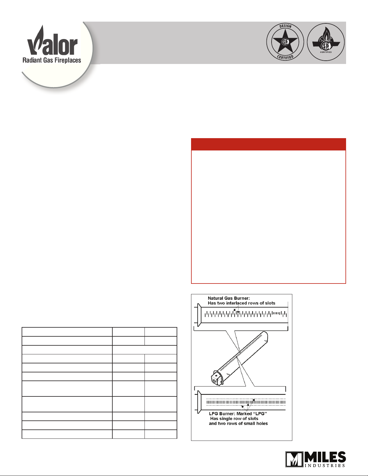
Burner identi cation
General Notes Regarding Conversion
The conversion may be done before or after the
appliance is installed into the cavity. However, the gas
must be connected to set the manifold pressure.
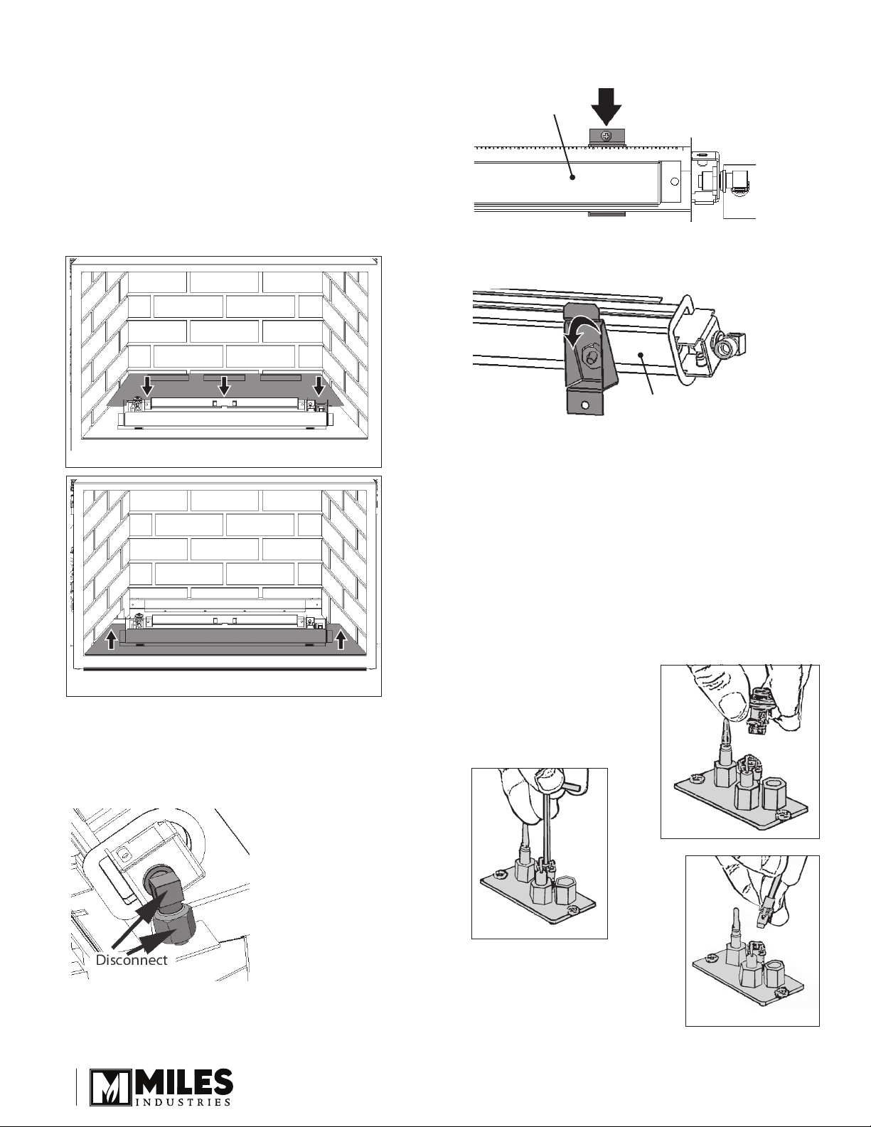
Prepare the appliance
1. If the replace is already installed, remove the
access side doors, the front trim, the window, the
fuel bed and the grate (with logs only).
2. Remove the front bricks, the rear log support (3
screws), the front brick support.
Remove the rear log support
2. Remove the 2 screws securing the burner brackets to
the burner tray.
Burner—top view
3. Detach the burner brackets from the burner by
removing 2 nuts using a 5/16” (8 mm) wrench.
Burner—underside view
4. Transfer the burner support brackets to the new
conversion burner securing them with the 2 nuts
removed in step 3. Note: do not overtighten the
nuts to avoid breaking the studs.
5. Verify that the new burner has the correct injector
before you install it on the burner tray—see
Specications table on page 1.
6. Reinstall the burner on the burner tray.
7. Reconnect the injector elbow to the pipe.
Remove the front brick support
3. Remove the ceramic panels.
Replace the burner
1. Disconnect the burner elbow injector nut from the
pipe using a 11/16” (17 mm) wrench.
Convert the pilot injector
Convert the pilot. Ensure the pilot head is snapped into
position correctly.
1. Remove the pilot hood by
pulling on it.
2. Unscrew the pilot injector
using an Allen key. Discard
the pilot injector.
3. Replace with the appropriate
pilot injector—see
Specications table on page 1.
Screw the new injector.
4. Ret the pilot head by pushing
down on it. Ensure that it snapps into position.
2
 Loading...