

PORTRAIT
Gas Conversion Kits
530NGK (LPG to NG) / 530PGK (NG to LPG)
Use with Valor Models 530 Heater ONLY
Installation Instructions
This appliance is certifi ed for use from 0–4500 feet. For
altitudes above 4500 feet, see local codes.
Kit Contents
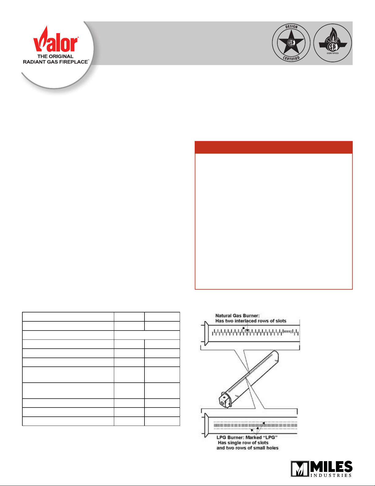
1 Pilot injector
1 Burner
1 Main burner elbow injector
1 Set of conversion labels
1 Set of air shutter
Tools Required
• Wrenches to disconnect gas line and 11/16” (17 mm)
and 7/16” (11 mm)
• Phillips (+) screwdriver, to remove burner module
• Small (jewelers size) fl at blade screwdriver, to set
pressure
• Small fl at blade screwdriver, to release pressure tap
on valve
• Needle nose pliers, to remove by-pass screw
• Manometer, to set manifold at the valve
Specifi cations
Model
Gas Natural Propane
Altitude (Ft.)* 0-4,500 feet*
Input Maximum (Btu/h) 20,500 19,000
Input Minimum (Btu/h) 6,500 12,500
Manifold Pressure (in w.c.) 3.7 10.5
Minimum Supply Pressure
(in w.c.)
Maximum Supply Pressure
(in w.c.)
Main Burner Injector Marking 580 200
Pilot Injector Marking 35 27
Min. Rate By-Pass Screw 125 125
530NG 530LPG
5.0 11.0
10.5 14.0
WARNING
This conversion kit shall be installed by a
qualifi ed service agency in accordance with
the manufacturer’s instructions and all applicable codes and requirements of the authority
having jurisdiction. If the information in these
instructions is not followed exactly, a fi re, ex-
plosion or production of carbon monoxide may
result causing property damage, personal injury or loss of life. The qualifi ed service agency
is responsible for the proper installation of this
kit. The installation is not proper and complete
until the operation of the converted appliance
is checked as specifi ed in the manufacturer’s
instructions supplied with the kit.
Use this manual in conjunction with the installation manual supplied with the appliance.
4004066-01
© Copyright Miles Industries Ltd., 2013.
General notes regarding conversion
The conversion may be done before or after the
appliance is installed into the cavity. However, the
gas must be connected in order to set the manifold
pressure.
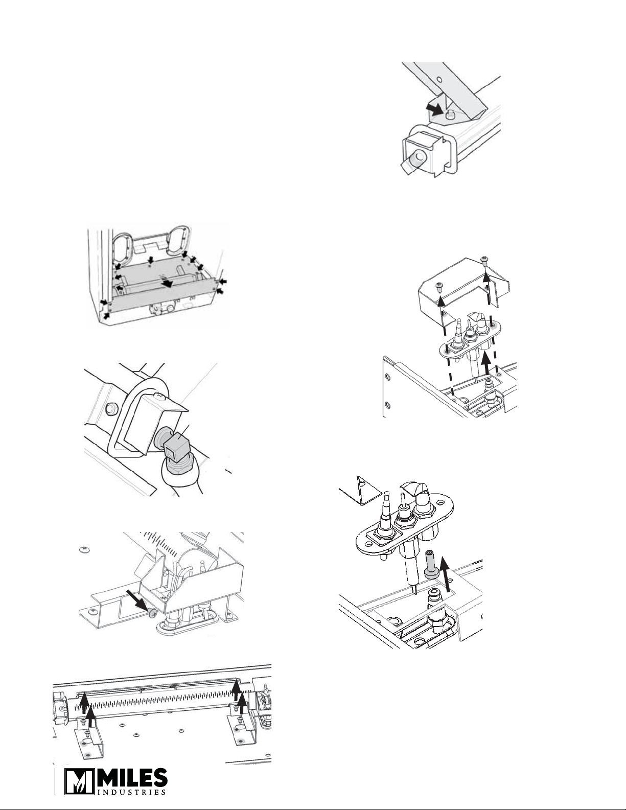
Prepare the appliance
1. If the fi replace is already installed, remove the front,
window and fuel bed.
2. Disconnect the gas inlet pipe from the inlet elbow
fi tting on the valve.
5. Detach the two burner support brackets from the
burner rail (2 nuts).
Conversion procedure
1. Detach the burner module (11 screws).
2. Disconnect the burner elbow injector from the pipe,
using a 11/16” (17 mm) wrench.
Disconnect
6. Disconnect the pilot unit and shield from its bracket
(2 screws).
7. Accessing pilot assembly from underside of module,
disconnect the pilot pipe, using a 7/16” (11 mm)
wrench.
8. Remove the pilot injector. Replace by the
appropriate pilot injector—see the Specifi cations
table on the fi rst page.
3. Remove the screw securing the pilot bracket to the
burner support bracket.
4. Detach the burner unit from the burner plate (4 screws).
Burner module rear view
2
Note - The pilot
injector should
be slipped onto
the end of the
pipe from the
side. The pilot
pipe, with injector
attached, should
be inserted into
the assembly.
9. Replace the main burner with the burner assembly
supplied and reassemble the module.
© Copyright Miles Industries Ltd., 2013.
 Loading...