

Valor PORTRAIT, PORTRAIT 569 Ledge Front Installation Instructions Manual
PORTRAIT
569 Ledge Front
CSA approved for use with Valor Models 530I Heaters ONLY
INSTALLATION INSTRUCTIONS
!
A barrier designed to reduce the risk of burns from the hot viewing
glass is provided with this appliance and shall be installed
for the protection of children and other at-risk individuals.
Notes: This kit must be installed or serviced by a qualifi ed
installer, service agency or gas supplier. These instructions are to
be used in conjunction with the main installation instructions
for Valor heater model 530I.
The installation of this kit affects the framing and method of
installing the 530 heater.
WARNING
HOT GLASS WILL
CAUSE BURNS.
DO NOT TOUCH GLASS
UNTIL COOLED.
NEVER ALLOW CHILDREN
TO TOUCH GLASS.
INSTALLER
Leave this manual
with the appliance.
CONSUMER
Retain this manual
for future reference.
Installation Sequence
1. Frame the cavity.
2. Install the heater with stud brackets, stand-offs, insulation, wall switch
kit, and cement board.
3. Gas fi t and vent heater.
4. Drywall only (no tile, etc.).
5. Assemble and install the mounting frame.
6. Install fi nishing material (tile, etc.). Finish around or under 570 Finishing
Plate if using it.
7. Install the trim panel fi tted with the barrier screen.
4002418-07
© Copyright Miles Industries Ltd., 2013.
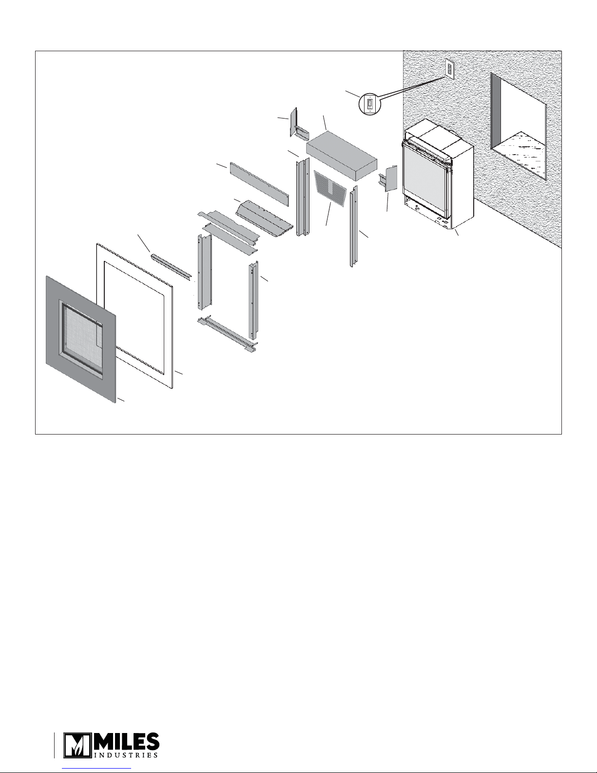
Overview
Touch control
wall switch
Window frame cover
Cement board
Convection baffl e
570FPB Finishing Plate
Stand-off
Stud bracket
Mounting
frame
Insulation
Roof
grille
panel
Stand-off
Stud bracket
530 engine
Trim panel —patina, brushed nickel or black—
with barrier screen
(530 engine and 570FPB Finishing Plate sold separately)
2
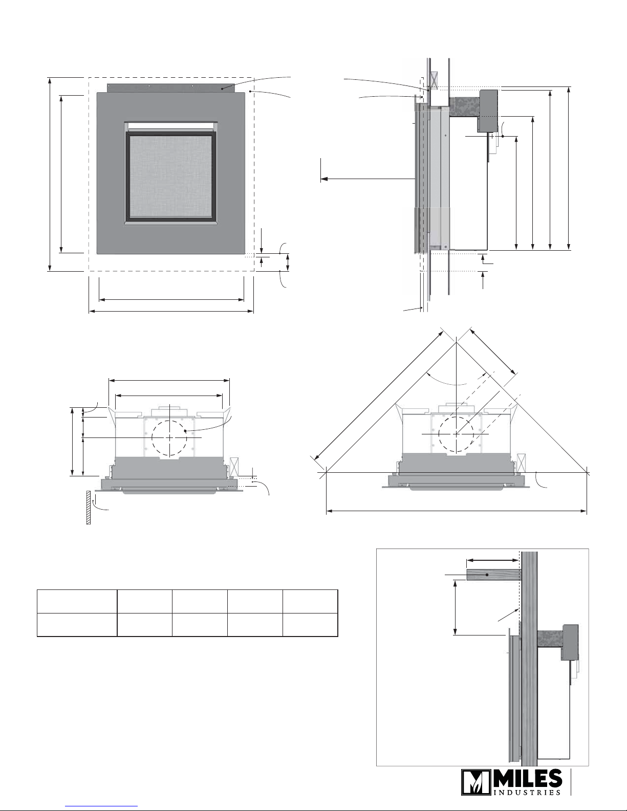
Dimensions & Clearances
30” (762 mm)
36-1/2” (927 mm)
Cement board
570 Finishing Plate
sold separately
1/2” (13 mm) min.
under bottom of
trim for air gap
bottom of trim
Min. 36” (0.9 m) to
combustible materials
center
of vent
21-5/8” (549 mm)
25-1/4” (641 mm)
30-1/4” (768 mm) to header base
31” (787 mm) to cement board top
2”
(51 mm)
12-3/4”
(324 mm)
surface
of wall
nish
to
3-5/8”
(92 mm)
7-1/8”
(181 mm)
2” (51 mm) sidewall
minimum clearance
Mantel Clearances
27-3/8” (696 mm)
31-1/8” (790 mm)
22-1/2” (572 mm)
20” (508 mm)
bottom of 570
570 plate thickness: 1/2” (13 mm)
6-5/8” (168 mm) dia.
cement board
and drywall
thickness:
1/2” (13 mm)
wall nish thickness
over top of drywall:
max 1” (25 mm),
1/2” (13 mm)
when using 570 Plate
3-5/16” (84 mm)
33-15/16” (861.3 mm)
Combustible
4” (102 mm) between
bottom of engine and
bottom of 570 plate
11-15/16”
(302.5 mm)
90°
47-15/16” (1216.9 mm)
mantel
11/16” (17 mm) between
bottom of engine and
bottom of trim
Face of
wall studs
A
Mantel Depth ‘A’
Mantel Height ‘B’
0–6”
(0–152 mm)8”(203 mm)
4”
(102 mm)8”(203 mm)
10”
(254 mm)
10”
(254 mm)
12”
(305 mm)
12”
(305 mm)
Side View
Face of
cement
B
board/
drywall
3
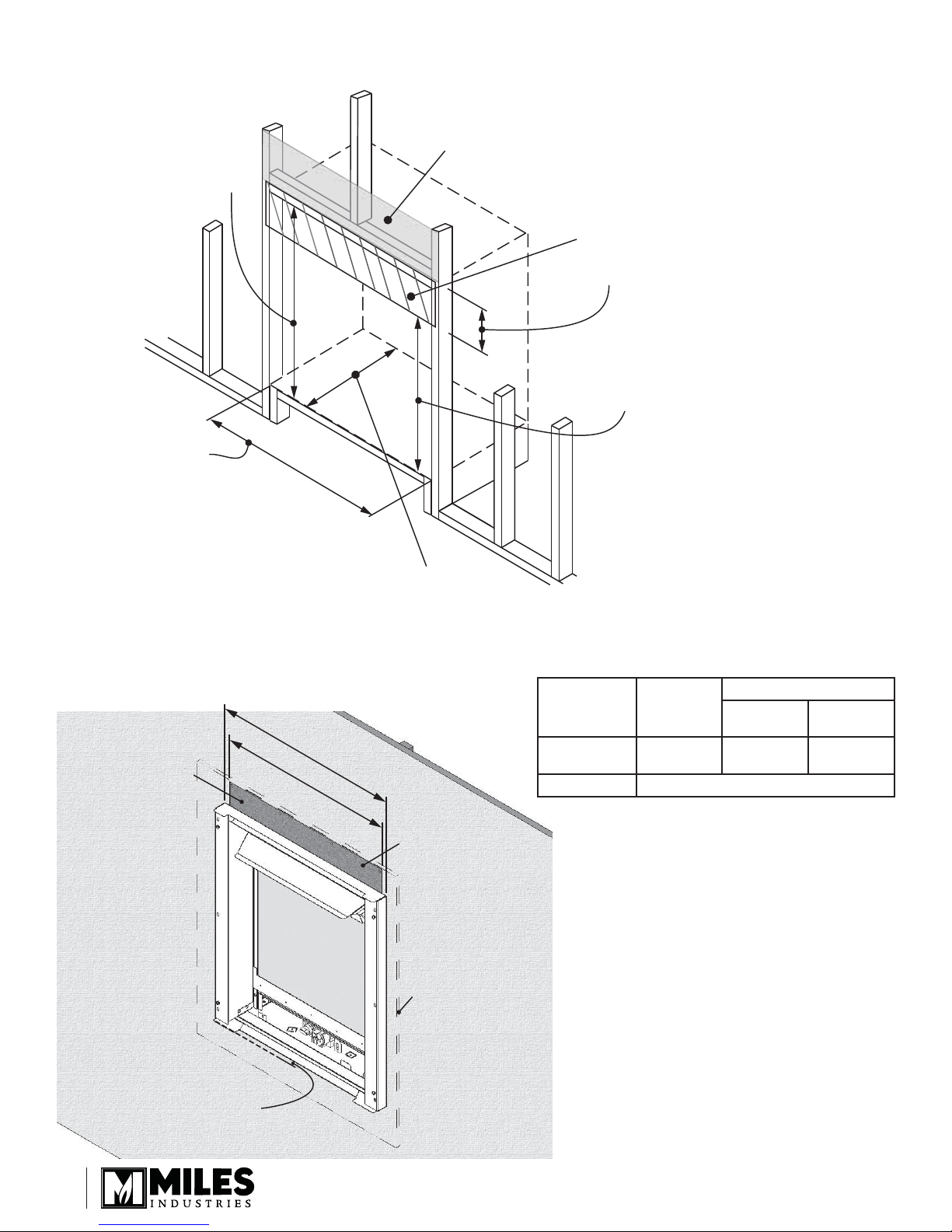
Framing
Wall Finish
30-1/4” (768 mm)
to header
3-5/8” (92 mm)
cement board
supplied
27-3/8” (695 mm) to
cement board
This is the framing
width. Drywall to
23-3/4” (603 mm) wide.
Wall Finish
cement board
drywall
22-1/2” min.
(572 mm)
Minimum 12-3/4” (324 mm)
(Allow extra for rear vent elbow)
25” (635 mm)
23-3/4” (603 mm)
wall nish must be
non-combustible
at top of opening
WALL
FINISH
Tile or fi nish
thickness
Drywall 1/2” (12.7 mm)
no 570
plate
1-1/8”
(30 mm)
with 570 fi nishing plate
tile up to
plate:
1-3/8”
(35 mm)
tile behind
plate:
5/8”
(18 mm)
gap must
remain open
for air ow
4
570 plate outline
Installation
tab at
the top
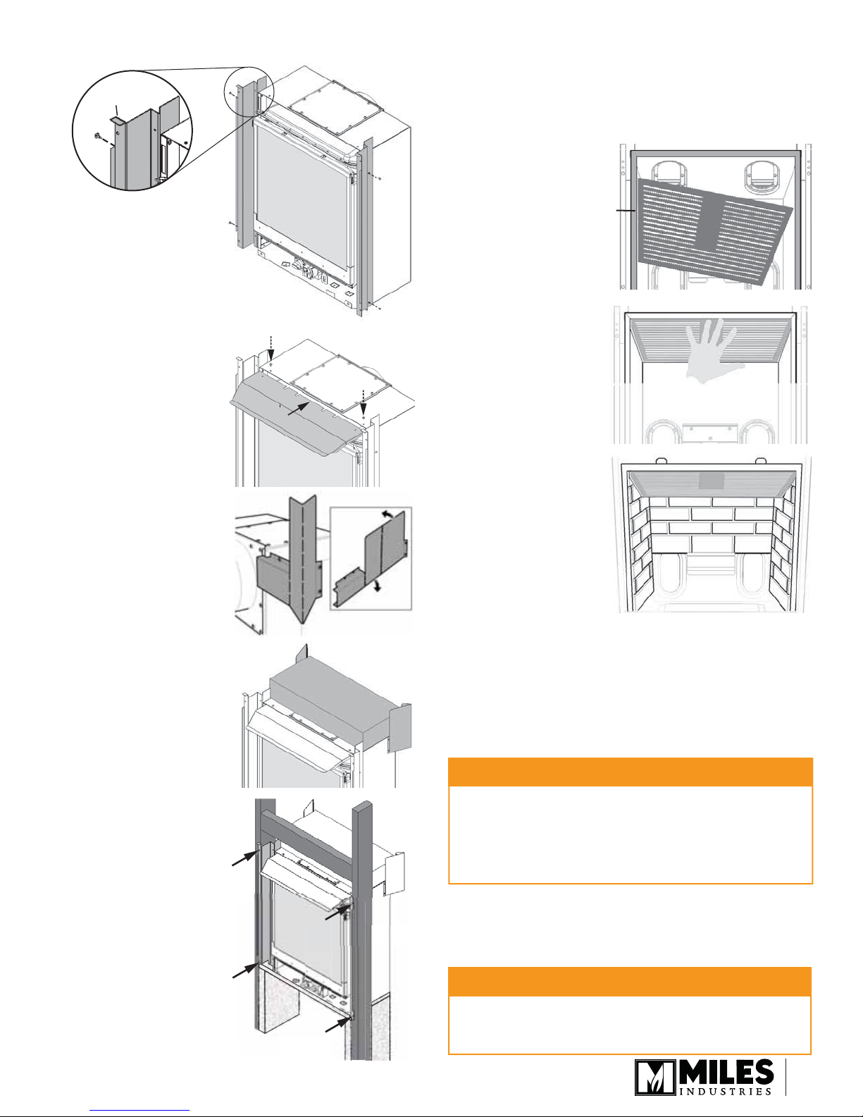
1. Fit the stud brackets
to the appliance’s
sides (2 screws/
side). Make sure the
horizontal tabs are at
the top.
2. Fit the convection
baffl e to the top of
the appliance case
(2 screws). The
convection baffl e
slips under the top of
the appliance case.
3. Required for
installation
in combustible
construction. Bend
the stand-offs into
shape and fi x them to
the appliance’s case
as indicated (4 screws/
side, pre-fi tted on
engine).
4. Required for
installation in
combustible
construction. Add
insulation pad on the
top of the appliance,
cutting around the pipe
if installing a top vent.
5. Mount the appliance
to the studs with
wood screws (2/side,
not supplied). Make
sure the framing is
leveled.
6. Proceed with the
installation of the
fi rebox, gas fi tting,
venting and so on
as per appliance
instruction manual.
LOGS & ROCKS VERSIONS ONLY. Grille cannot
be used with coal fuel bed version. Install the grille
panel inside the appliance:
a. Insert the grille in the fi rebox by aligning one
of its side edge to the edge of the fi rebox as
indicated.
Grille inserted
parallel to
fi rebox edge
b. Raise the grille up
to cover the top
fi rebox ports
and hold with
one hand.
Note: The port
cover strip
supplied with
the heater is not
required.
c. Place the rear
brick wall. It
should support
the grille. If not,
keep holding it
while you place
the side brick
walls. Refer to
the fi replace
installation manual for more information on
installing the brick walls.
7. Install Touch control wall switch. The wall switch
comes with a 26-foot wire and a cover plate. The
switch is connected to the receiver in the fi replace.
The receiver is located left of the control valve
under the burner module.
CAUTION
DO NOT PUT BATTERIES IN THE REMOTE
CONTROL RECEIVER until the wires are
connected to the burner control unit as shortcircuit could result in the destruction of the
electrical components.
a. Decide where the switch is to be installed. Install
an electrical outlet box (not supplied).
b. Thread the switch wire through an access hole
in the appliance.
CAUTION
Do not run the switch wire over the top of the
fi rebox. Route the wire so it does not contact the
fi rebox.
5
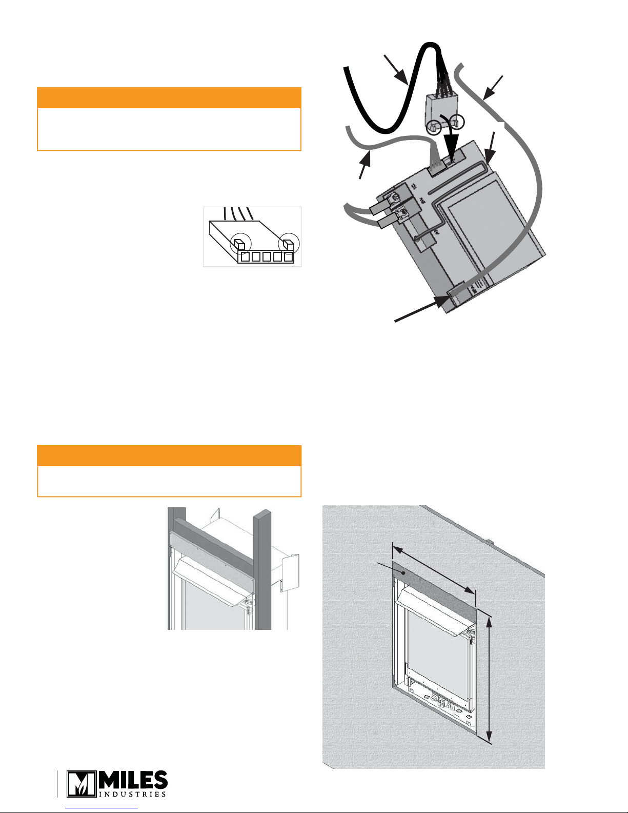
c. Pull out the receiver box. Remove the batteries
from the receiver box if it contains any. You
can remove the ignition wire to improve access
to the receiver.
CAUTION
Wall Switch
Harness
Ignition Wire
DO NOT USE a screwdriver or other metallic object to
remove the batteries from the receiver or the handset!
This could cause a short circuit to the receiver.
d. Take the switch wire and plug it into the
receiver’s connection slot as indicated (the other
slot should already be fi tted with the valve’s wire
harness connector). See diagram at right.
IMPORTANT: The
connection can only be
done one way. Do not
force it or damage the
pins!
e. On the outside of the fi replace, run the switch
wire into the outlet box.
f. Plug the wire into the switch plate and to the
outlet box.
g. Reconnect the ignition wire to the receiver if it
was previously removed.
h. Insert 4 AA batteries in the receiver. Replace the
cover.
i. Test the operation of the wall switch.
j. Fix the wall cover plate to the outlet box.
k. Replace the receiver in its position and as well
as the antenna if deployed.
Antenna
Valve Wire
Harness
Ignition Wire
Connection
(spade type
connector)
Be careful when
removing and
reinstalling: not to
bend or break the
spade connector
CAUTION
To avoid short-circuit to the receiver, position the antenna
so that it DOES NOT TOUCH the ignition wire.
8. Install the cement
board on top of the
appliance. The board
sits on the horizontal
tabs at the top of the
stud brackets.
9. Install the drywall at this point. Although it can be
installed later, the mounting frame for the front will
overlap it.
Wall opening: 23-3/4” (w) x 31” (h)
Note: If tiling, etc. is used overtop of drywall,
complete steps 10, 11, and 12 fi rst as the frame,
once installed, will defi ne where to tile up to.
Cement
board
Drywall opening
23-3/4”
(603 mm)
31”
(787 mm)
6
 Loading...