

Valor Madrona MF28ILN, Madrona MF28ILP Installation & Owner's Manual
MADRONA
FS DV Gas Stove
MF28ILN (NG) & MF28ILP (LPG)
Engine to be installed ONLY with the cast stove body MFCS01 or MFCS02
Installation & Owner’s Manual
INSTALLER
HOT GLASS WILL
CAUSE BURNS.
DO NOT TOUCH GLASS
UNTIL COOLED.
NEVER ALLOW CHILDREN
TO TOUCH GLASS.
WARNING: If the information in these
instructions is not followed exactly, a fi re
or explosion may result causing property
damage, personal injury or loss of life.
Do not store or use gasoline or other
fl ammable vapors and liquids in the vicinity
of this or any other appliance.
WHAT TO DO IF YOU SMELL GAS
• Do not try to light the appliance.
• Do not touch any electrical switch; do not
use any phone in your building.
• Immediately call your gas supplier from a
neighbor’s phone. Follow the gas supplier’s
instructions.
• If you cannot reach your gas supplier, call
the fi re department.
Installation and service must be performed
by a qualifi ed installer, service agency or the
gas supplier.
Leave this manual
with the appliance.
CONSUMER
Retain this manual
for future reference.
Please read this manual BEFORE installing
and operating this appliance.
This appliance may be installed in an
after-market permanently located,
manufactured (mobile) home where not
prohibited by local codes.
This appliance is only for use with the type
of gas indicated on the rating plate. This
appliance is not convertible for use with
other gases, unless a certifi ed kit is used.
This appliance is a domestic room-heating
appliance. It must not be used for any other
purposes such as drying clothes, etc.
This appliance is suitable for installation in a
bedroom or bed sitting room.
Massachusetts: The piping and fi nal
gas connection must be performed by a
licensed plumber or gas fi tter in the State of
Massachusetts. Also, see Carbon Monoxide
Detector requirements under “Safety and
Warning Information” on page 6.
Ce guide est disponible en français sur demande.
4001917-09
©2011, Miles Industries Ltd.
Manufactured by
MILES INDUSTRIES LTD., British Columbia, Canada
www.valorfi replaces.com
Thank You ...
For purchasing a Valor Madrona. Your new radiant gas heater is a technical appliance
that must be installed by a qualifi ed dealer. Each Madrona is fully tested during the
production process for your safety and comfort.
Your unit has been professionally installed by:
Dealer Name _______________________________________
Phone Number ______________________________________
Should you encounter an operational problem, call your dealer immediately.
Do not try to repair the unit as you may cause an injury or damage the fi replace.
The information contained in this installation manual is believed to be correct at
the time of printing. Miles Industries Ltd. reserves the right to change or modify any
information or specifi cations without notice. Miles Industries Ltd. grants no warranty,
implied or stated, for the installation or maintenance of your heater, and assumes no
responsibility for any consequential damage(s).
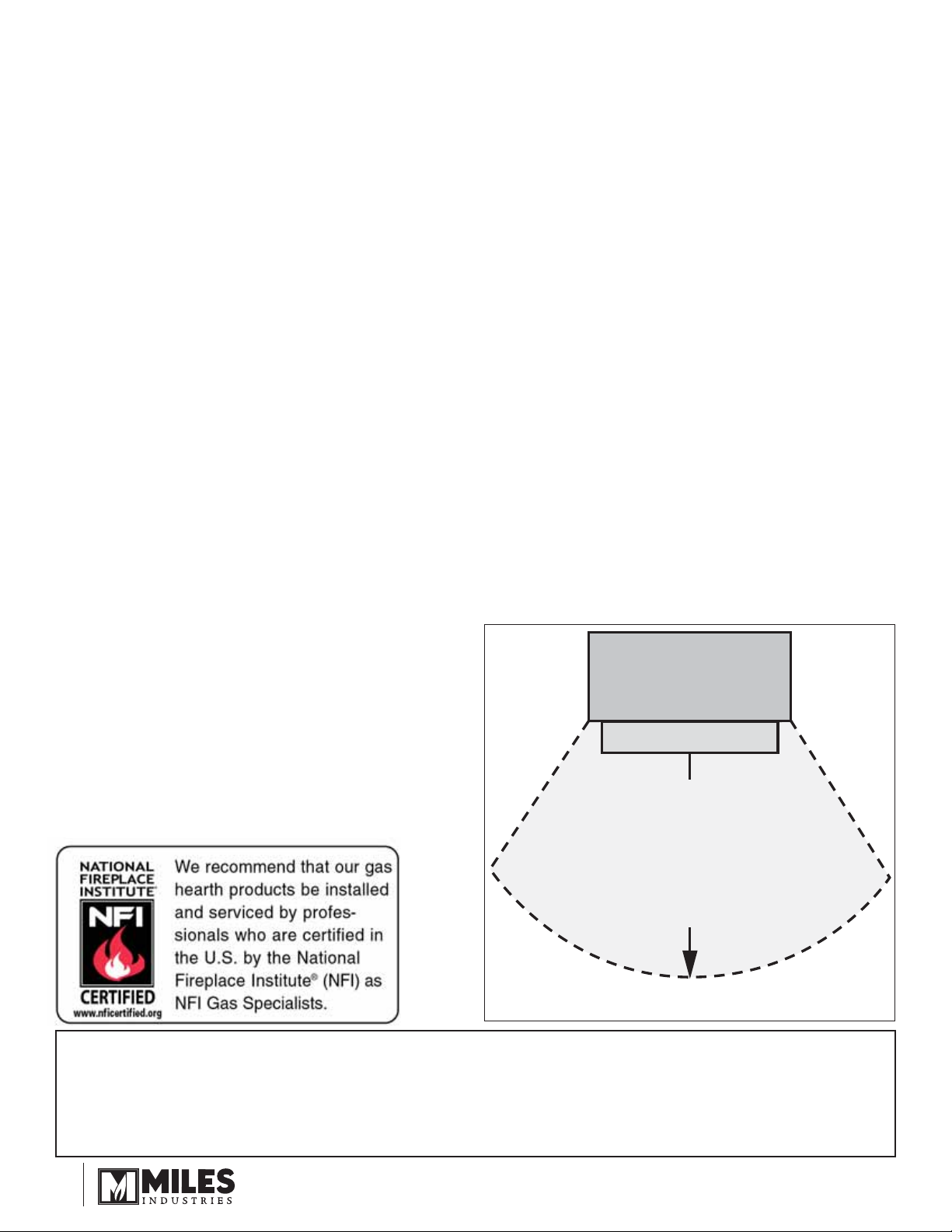
Fireplace
Hearth
Do not put
furniture or other objects
in this space in front of
the replace:
36” (0.9 m)
Designed and Manufactured by / for
Miles Industries Ltd.
190–2255 Dollarton Highway, North Vancouver, BC, CANADA V7H 3B1
Tel. 604-984-3496 Fax 604-984-0246
www.valorfi replaces.com
© Copyright Miles Industries Ltd., 2011
2
Safety and Your Fireplace
Safety and Your Fireplace
Please Read and Carefully Follow all Safety Warnings and
Operating Instructions Contained in Your Owners Manual
(Replacement Manuals are available by contacting our service department at
1-800-468-2567 or visit www.valorfi replaces.com).
Please Follow These Important
Child Safety Precautions and
Recommendations,
• Parts of your Valor Fireplace become
extremely hot while in operation.
• The glass viewing window
temperature can
exceed 500 F
at full capacity.
Momentary contact
with a hot glass
surface can cause
a severe burn, even if the fi replace
is operating at reduced heating
capacity.
• The glass window will remain hot
for an extended period of time after
the fi replace has been turned off.
Ensure that children are prevented
from touching the fi replace during the
cool down period.
• Toddlers and Y oung Children
must be closely supervised at all
times when they are in the same
room as the operating fi replace. They
lack full awareness of danger and
rely on your protection. Toddlers,
in particular, do not have the motor
skills and response refl exes to
withdraw in the event of accidental
contact with a hot surface.
• A physical barrier is strongly
recommended if there are young
children, or at-risk individuals in the
house. Install an approved aftermarket safety gate to keep toddlers,
young children and other at-risk
individuals a safe distance from the
fi replace.
• Keep the remote control handset
out of reach of children at all
times. A wall mount storage holster
is provided with your remote control
handset.
• Ensure that the fi replace, including
the pilot light, is completely turned
off when children are present and
close supervision and safety barriers
are not available—see page 29 of
Owner’s Information section.
• If the fi replace is not going to be used
for the summer or any extended
period of time, remove the batteries
from the remote control handset
and receiver. It is recommended that
batteries are replaced annually in any
event—see page 28.
3

Table of Contents
Safety and Your Fireplace .............................................................................3
Safety & Warning Information ......................................................................5
Specifi cations ................................................................................................8
Dimensions & Clearances .............................................................................9
Venting ..........................................................................................................11
Installation Planning ....................................................................................16
Packs Contents—Appliance & Castings ...................................................16
Appliance Preparation .................................................................................17
Supply Gas Installation ...............................................................................22
Ceramic Logs Installation ...........................................................................23
Window Refi tting .........................................................................................24
Remote Control Initial Set-up .....................................................................24
Operation Check & Aeration Settings Adjustment ...................................25
Front & Top Installation ...............................................................................25
Remote Control Handset Wall Holder Installation ....................................26
Owner’s Information ....................................................................................27
Remote Control Operation ..........................................................................30
◊
Options .........................................................................................................34
Lighting Instructions ...................................................................................35
Wiring Diagram ............................................................................................36
Approved Venting Components .................................................................37
◊
Warranty .......................................................................................................39
Replacement Parts ......................................................................................40
= Updated content
◊
4
Safety & Warning Information
OWNER’S INFO
READ and UNDERSTAND all instructions carefully
before starting the installation. FAILURE TO
FOLLOW these installation instructions may result in
possible fi re hazard and will void the warranty.
Prior to the fi rst fi ring of the fi replace, READ the
Owner’s Information section of this manual.
DO NOT USE this appliance if any part has been
under water. Immediately, CALL a qualifi ed service
technician to inspect the unit and to replace any part
of the control system and any gas control that has
been under water.
THIS UNIT IS NOT FOR USE WITH SOLID FUEL.
Installation and repair should be PERFORMED
by a qualifi ed service person. The appliance and
venting system should be INSPECTED before initial
use and at least annually by a professional service
person. More frequent cleaning may be required due
to excessive lint from carpeting, bedding, etc. It is
IMPERATIVE that the unit’s control compartment,
burner, and circulating air passageways BE KEPT
CLEAN to provide for adequate combustion and
ventilation air.
Always KEEP the appliance clear and free from
combustible materials, gasoline, and other fl ammable
vapors and liquids.
NEVER OBSTRUCT the fl ow of combustion and
ventilation air. Keep the front of the appliance CLEAR
of all obstacles and materials for servicing and proper
operation.
Due to the high temperature, the appliance should be
LOCATED out of traffi c areas and away from furniture
and draperies. Clothing or fl ammable material
SHOULD NOT BE PLACED on or near the appliance.
Children and adults should be ALERTED to the
hazards of high surface temperature and should STAY
AWAY to avoid burns or clothing ignition.
This unit MUST be used with a vent system as
described in this installation manual. NO OTHER vent
system or components MAY BE USED.
This gas fi replace and vent assembly MUST be
vented directly to the outside and MUST NEVER be
attached to a chimney serving a separate solid fuel
burning appliance. Each gas appliance MUST USE
a separate vent system. Common vent systems are
PROHIBITED.
INSPECT the external vent cap on a regular basis to
make sure that no debris, plants, trees, shrubs are
interfering with the air fl ow.
The glass door assembly MUST be in place and
sealed before the unit can be placed into safe
operation.
DO NOT OPERATE this appliance with the glass
door removed, cracked, or broken. Replacement of
the glass door should be performed by a licensed or
qualifi ed service person. DO NOT strike or slam the
glass door.
The glass door assembly SHALL ONLY be replaced
as a complete unit, as supplied by the fi replace
manufacturer. NO SUBSTITUTE material may be
used.
DO NOT USE abrasive cleaners on the glass door
assembly. DO NOT ATTEMPT to clean the glass door
when it is hot.
TURN OFF the gas before servicing this appliance.
It is recommended that a qualifi ed service technician
perform an appliance check-up at the beginning of
each heating season.
Any safety screen or guard removed for servicing
MUST BE REPLACED before operating this
appliance.
DO NOT place furniture or any other combustible
household objects within 36” of the fi replace front.
YOUNG CHILDREN should be CAREFULLY
SUPERVISED when they are in the same room as
the appliance. Toddlers, young children and others
may be susceptible to ACCIDENTAL CONTACT
BURNS. A physical barrier is recommended if there
are at risk individuals in the house. To restrict access
to a fi replace or stove, INST ALL AN ADJUSTABLE
SAFETY GATE to keep toddlers, young children and
other at risk individuals out of the room and away
from hot surfaces.
BE CAREFUL not to put any decorating objects
sensitive to heat to close above or around the
fi replace as it gets very hot when operating.
DO NOT use this heater as a temporary source of
heat during construction.
This appliance is a DOMESTIC ROOM-HEATING AP-
PLIANCE. It must not be used for any other purposes
such as drying clothes, etc.
5

OWNER’S INFO
Safety & Warning Information
Operating Your Fireplace for the First Time
When operating your new fi replace for the fi rst time,
some vapors may be released due to the burning of
curing compounds used in the manufacture of the
appliance. They may cause a slight odor and could
cause the fl ames to be the full height of the fi rebox, or
even slightly higher, for the fi rst few hours of operation.
It is also possible that these vapors could set off any
smoke detection alarms in the immediate vicinity.
These vapors are quite normal on new appliances. We
recommend opening a window to vent the room. After
a few hours’ use, the vapors will have disappeared and
the fl ames will be at their normal height.
State of California. Proposition 65 Warning.
Fuels used in gas, wood-burning or oil fi red appliances,
and the products of combustion of such fuels, contain
chemicals known to the State of California to cause
cancer, birth defects and other reproductive harm.
California Health & Safety Code Sec. 25249.6.
State of Massachusetts Carbon Monoxide
Detector/Vent Terminal Signage
Requirements
For all side wall horizontally vented gas fueled
equipment installed in every dwelling, building or
structure used in whole or in part for residential
purposes, including those owned or operated by the
Commonwealth and where the side wall exhaust
vent termination is less than seven (7) feet above
fi nished grade in the area of the venting, including
but not limited to decks and porches, the following
requirements shall be satisfi ed:
1. INSTALLATION OF CARBON MONOXIDE
DETECTORS. At the time of installation of the side wall
horizontal vented gas fueled equipment, the installing
plumber or gasfi tter shall observe that a hard wired
carbon monoxide detector with an alarm and battery
back-up is installed on the fl oor level where the gas
equipment is to be installed. In addition, the installing
plumber or gasfi tter shall observe that a battery
operated or hard wired carbon monoxide detector
with an alarm is installed on each additional level of
the dwelling, building or structure served by the side
wall horizontal vented gas fueled equipment. It shall
be the responsibility of the property owner to secure
the services of qualifi ed licensed professionals for the
installation of hard wired carbon monoxide detectors.
a. In the event that the side wall horizontally vented
gas fueled equipment is installed in a crawl space or
an attic, the hard wired carbon monoxide detector with
alarm and battery back-up may be installed on the next
adjacent fl oor level.
b. In the event that the requirements of this subdivision
can not be met at the time of completion of installation,
the owner shall have a period of thirty (30) days
to comply with the above requirements; provided,
however, that during said thirty (30) day period, a
battery operated carbon monoxide detector with an
alarm shall be installed.
2. APPROVED CARBON MONOXIDE DETECTORS.
Each carbon monoxide detector as required in
accordance with the above provisions shall comply
with NFPA 720 and be ANSI/UL 2034 listed and IAS
certifi ed.
3. SIGNAGE. A metal or plastic identifi cation plate
shall be permanently mounted to the exterior of the
building at a minimum height of eight (8) feet above
grade directly in line with the exhaust vent terminal for
the horizontally vented gas fueled heating appliance
or equipment. The sign shall read, in print size no less
than one-half (1/2) inch in size, “GAS VENT DIRECTLY
BELOW. KEEP CLEAR OF ALL OBSTRUCTIONS”.
4. INSPECTION. The state or local gas inspector of
the side wall horizontally vented gas fueled equipment
shall not approve the installation unless, upon
inspection, the inspector observes carbon monoxide
detectors and signage installed in accordance with the
provisions of 248 CMR 5.08(2)(a)1 through 4.
(b) EXEMPTIONS: The following equipment is exempt
from 248 CMR 5.08(2)(a)1 through 4:
1. The equipment listed in Chapter 10 entitled
“Equipment Not Required To Be Vented” in the most
current edition of NFPA 54 as adopted by the Board;
and
2. Product Approved side wall horizontally vented
gas fueled equipment installed in a room or structure
separate from the dwelling, building or structure used in
whole or in part for residential purposes.
(c) MANUFACTURER REQUIREMENTS - GAS
EQUIPMENT VENTING SYSTEM PROVIDED.
When the manufacturer of Product Approved side
wall horizontally vented gas equipment provides a
venting system design or venting system components
with the equipment, the instructions provided by the
manufacturer for installation of the equipment and the
venting system shall include:
6

Safety & Warning Information
1. Detailed instructions for the installation of the venting
system design or the venting system components; and
2. A complete parts list for the venting system design or
venting system.
(d) MANUFACTURER REQUIREMENTS - GAS
EQUIPMENT VENTING SYSTEM NOT PROVIDED.
When the manufacturer of a Product Approved side
wall horizontally vented gas fueled equipment does
not provide the parts for venting the fl ue gases, but
identifi es “special venting systems”, the following
requirements shall be satisfi ed by the manufacturer:
1. The referenced “special venting system” instructions
shall be included with the appliance or equipment
installation instructions; and
2. The “special venting systems” shall be Product
Approved by the Board, and the instructions for that
system shall include a parts list and detailed installation
instructions.
(e) A copy of all installation instructions for all Product
Approved side wall horizontally vented gas fueled
equipment, all venting instructions, all parts lists
for venting instructions, and/or all venting design
instructions shall remain with the appliance or
equipment at the completion of the installation.
OWNER’S INFO
7
INSTALLATION
Specifi cations
Approval & Codes
This appliance is certifi ed to ANSI Z21.88-2009/
CSA 2.33-2009 American National Standard / CSA
Standard for Vented Gas Fireplace Heaters for use in
Canada and USA, and to CGA 2.17-91 High Altitude
Standard in Canada. This appliance is for direct vent
installations.
Conversion between fuels may only be done using
the approved conversion kits listed on page 33. This
appliance complies with CSA P4.1-09 Testing method
for measuring annual fi replace effi ciencies.
The installation must conform to local codes or, in the
absence of local codes, with the National Fuel Gas
Code, ANSI Z223.1 or the Natural Gas and Propane
Installation Code CAN/CGA-B149. Only qualifi ed
licensed or trained personnel should install this
appliance.
This appliance, when installed with the optional
circulating fan kit (blower), must be electrically
grounded in accordance with local codes, or, in the
absence of local codes, with the National Electrical
Code, ANSI/NFP A 70 or the Canadian Electrical Code,
CSA C22.1.
For installations at elevations above 4,500 feet
(1,370 m) in Canada, please consult provincial
and/or local authorities having jurisdiction.
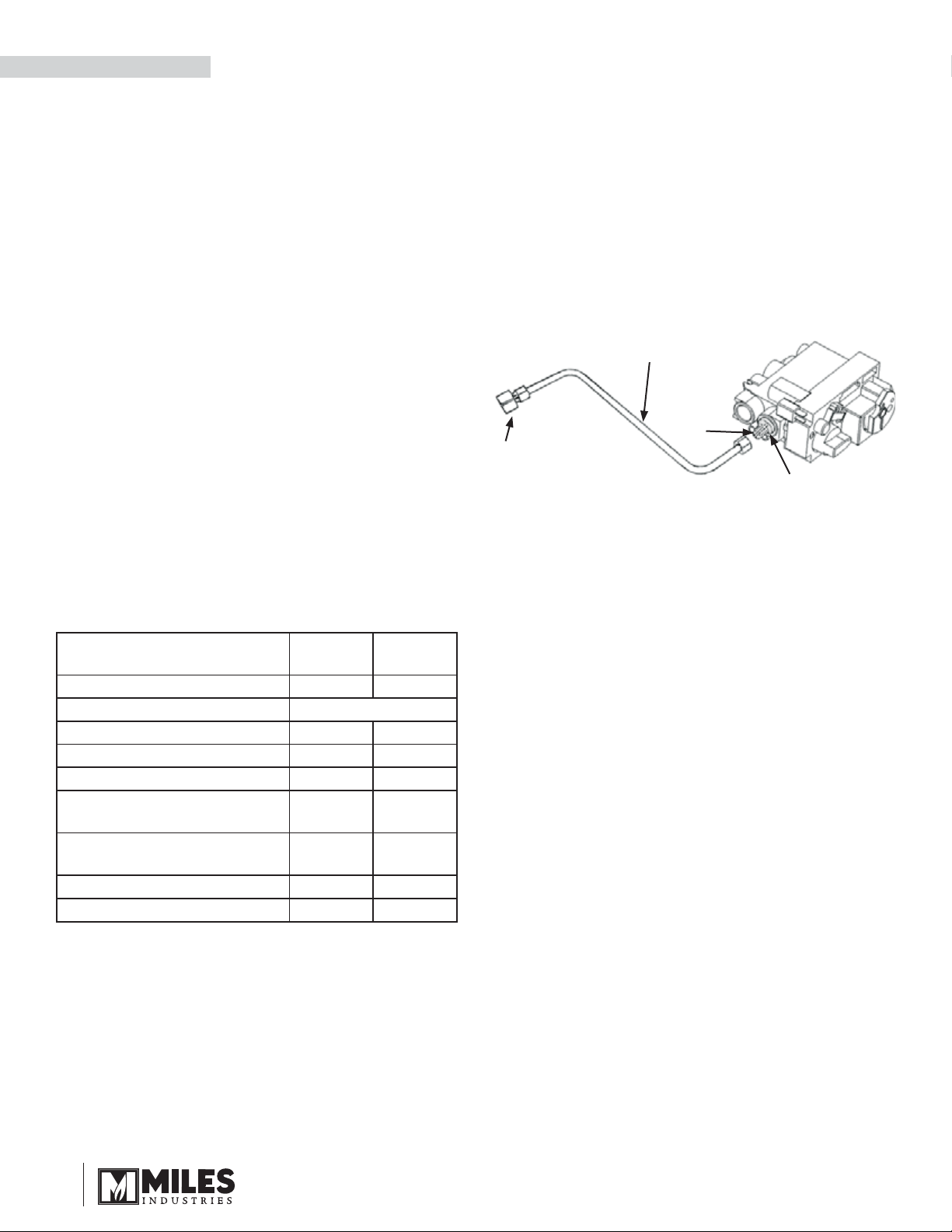
Supply Gas
Heater engine MF28ILN is used with natural gas.
Heater engine MF28ILP is used with propane gas.
The supply pressure must be between the limits
shown in the Ratings section above.
The supply connection is 3/8” NPT female.
5/16” O.D.
tubing
5/16”
fl are
3/8” N.P.T.
Female
3/8” N.P.T.
Electrical
The Madrona stove does not require an electrical
power source unless it is fi tted with an optional
circulating fan—see page 20.
Ratings
Model (Field convertible Top
or Rear Vent Outlet)
Gas Natural Propane
Altitude (Ft)* 0-4,500 feet*
Input Maximum (Btu/h) 28,000 28,000
Input Minimum (Btu/h) 6,500 14,500
Manifold Pressure (in w.c.) 3.75 10.5
Minimum Supply Pressure
(in w.c.)
Maximum Supply Pressure
(in w.c.)
Main Burner Injector Marking 82-750 92-300
Pilot Injector Marking 35 27
MF28ILN MF28ILP
5.0 11.0
11.0 14.0
*High Altitude Installations
Input ratings are shown in BTU per hour and are
certifi ed without deration for elevations up to 4,500 feet
(1,370 m) above sea level.
For elevations above 4,500 feet (1,370 m) in USA,
installations must be in accordance with the current
ANSI Z223.1 and/or local codes having jurisdiction.
Heating value of gas in some areas is reduced to
compensate for elevation—consult your local gas
utility to confi rm.
8
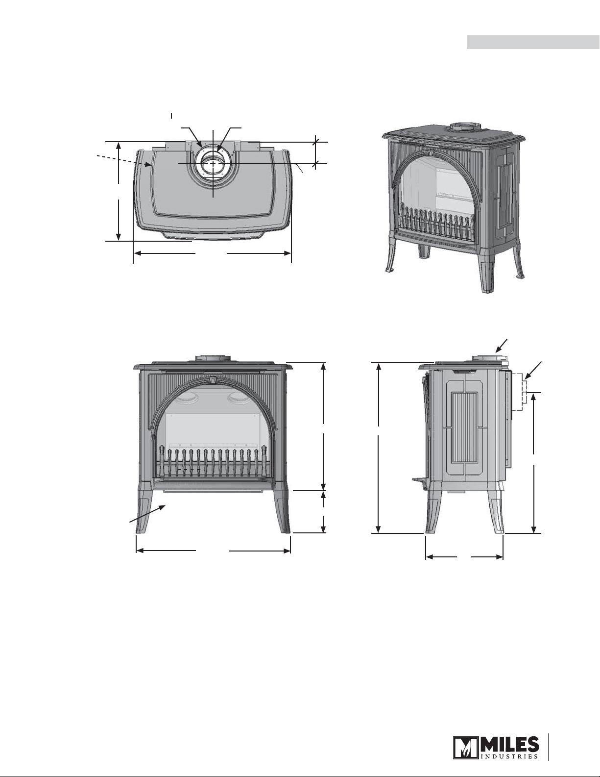
Dimensions
Dimensions & Clearances
INSTALLATION
Gas
inlet
position
3/8”
fem.
NPT
17-7/8”
Inlet collar
Ø 6-5/8”
x
Exhaust
collar Ø 4”
4”
Center
line
28-1/2”
Supplied
with top
vent; fi eld
convertible
to rear vent
Gas
inlet
position
3/8”
fem.
NPT
x
27-1/2”
Hearth Requirements
This unit is approved for mounting directly on
combustible wood fl ooring. If installed directly on
carpeting, vinyl or soft combustible fl oor other than
wood, it must be installed on a metal or wood panel
covering a minimum surface of 15 inches deep by
28 inches width.
23”
7-1/2”
30-1/2”
25-1/8”
14”
9
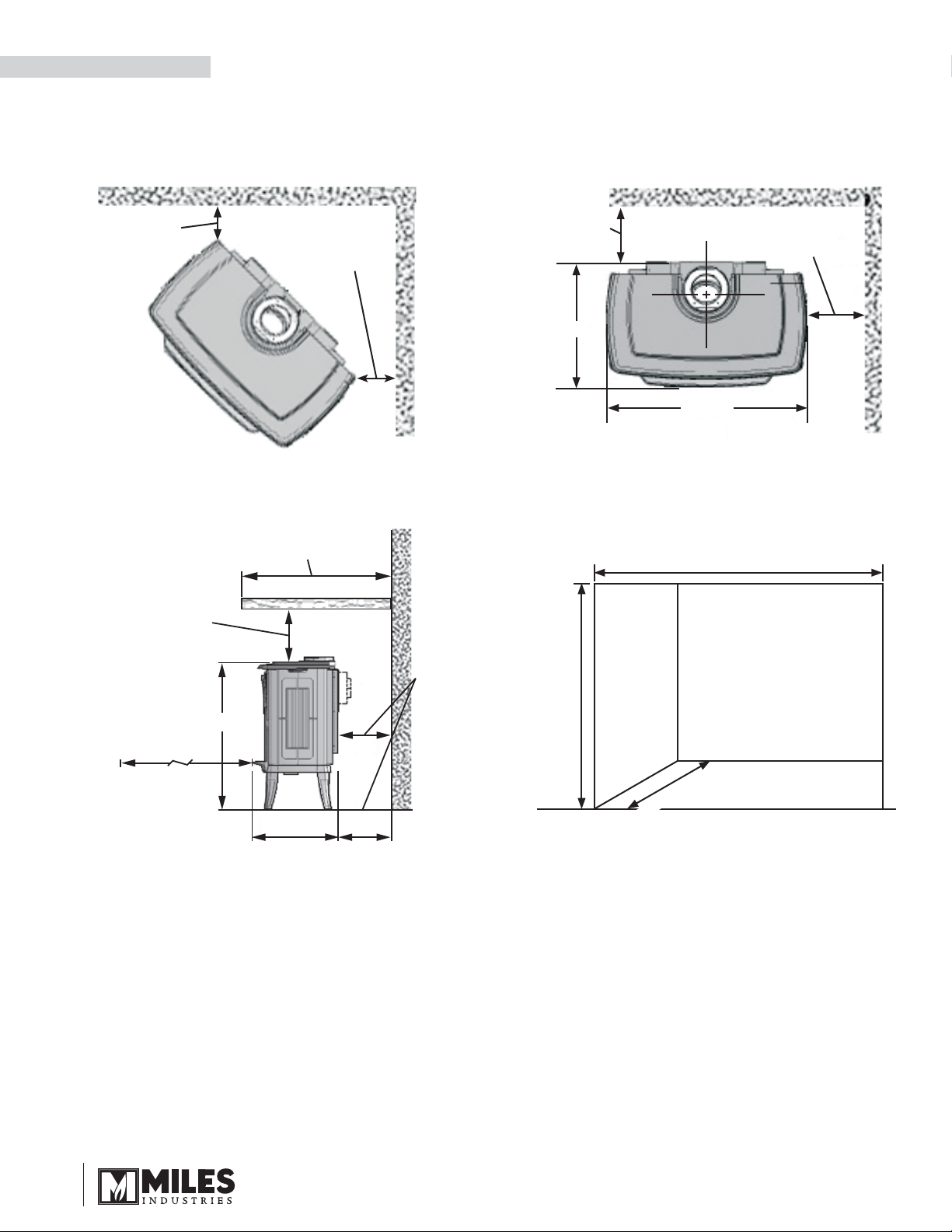
INSTALLATION
Clearances
Min. 5”
between
combustible
wall and
stove
Corner clearances Wall clearances
Dimensions & Clearances
Min. 5” between
combustible wall
and stove
Min. 5”
between
combustible
wall and rear
of stove
17-7/8”
Min. 6” between
combustible wall
and side of stove
28-1/2”
Maximum 26” from wall for
projection of combustible
Minimum 12”
between
stove and
combustible
mantel or
shelf
30-1/2”
Min. 36”
Keep a
minimum
of 36” of space
in front of stove
free of furniture
or object
17-7/8”
Mantel / shelf clearances
mantel or shelf
5”
40-1/2” minimum
5” between
combustible
wall and
back of stove
43-1/2” minimum
26” maximum
Alcove clearances
10
Venting
INSTALLATION
Top / Rear Outlet
This unit is shipped with a top outlet collar which is
fi eld-convertible to rear outlet—see page 21 for details.
Vent Material
This unit is approved for installation using 4 by 6-5/8
inches co-axial direct vent pipe and accessories—see
list of approved venting pipes and accessories on
pages 37–38.
This unit may also be converted to co-linear (two 3
inches) venting (rear vent only) for use in solid-fuel
burning fi replaces and chimneys using adapters and
accessories—see list of approved venting pipes and
accessories on pages 37–38. Instructions for co-linear
conversion are packaged with the co-linear adapter.
Do not mix components from different vent
manufacturers, with the exception of Valor’s 551DVK
Horizontal Termination Kit which can be used in
combination with approved manufacturers’ venting
pipes listed on pages 37–38. Follow the installation
instructions supplied with the individual venting
components.
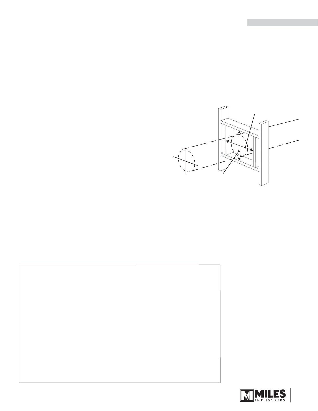
Framing Vent in Combustible
Walls & Ceilings
When penetrating through combustible walls and
ceilings, frame a minimum of 10 by 10 inches opening
to ensure that the insulation is kept clear of the vent
pipe. Also, seal all joints between the wall plates,
the wall and the vent pipe. Follow the installation
instructions supplied with the individual venting
components.
10” (254 mm)
Align the vent
center to the
center of the
frame
10” (254 mm)
Wall Thickness
The appliance vent is suitable for penetrating a
combustible wall assembly up to 14 inches (36 cm)
in thickness. A non-combustible wall can be of any
thickness up to the maximum horizontal run of vent
pipe allowed for the particular installation.
Important Installer Notice – Weather Sealing & Vapor
Barriers
It is the installer’s responsibility to ensure that vent installations through
exterior walls are caulked and weatherproofed in such a manner as to:
• Prevent rain water from entering the wall from the weather side by
adequately caulking the outer vent plate to the exterior wall surface.
• Prevent moisture inside the home from penetrating into the wall
structure by ensuring the inside wall plate is adequately sealed to
the inside vapor barrier.
• Prevent rain water and moisture from entering the walls by sealing
the joints between the outer vent tube and the inner and outer wall
plates.
We recommend the use of a high quality polyurethane sealant.
11
INSTALLATION
Venting
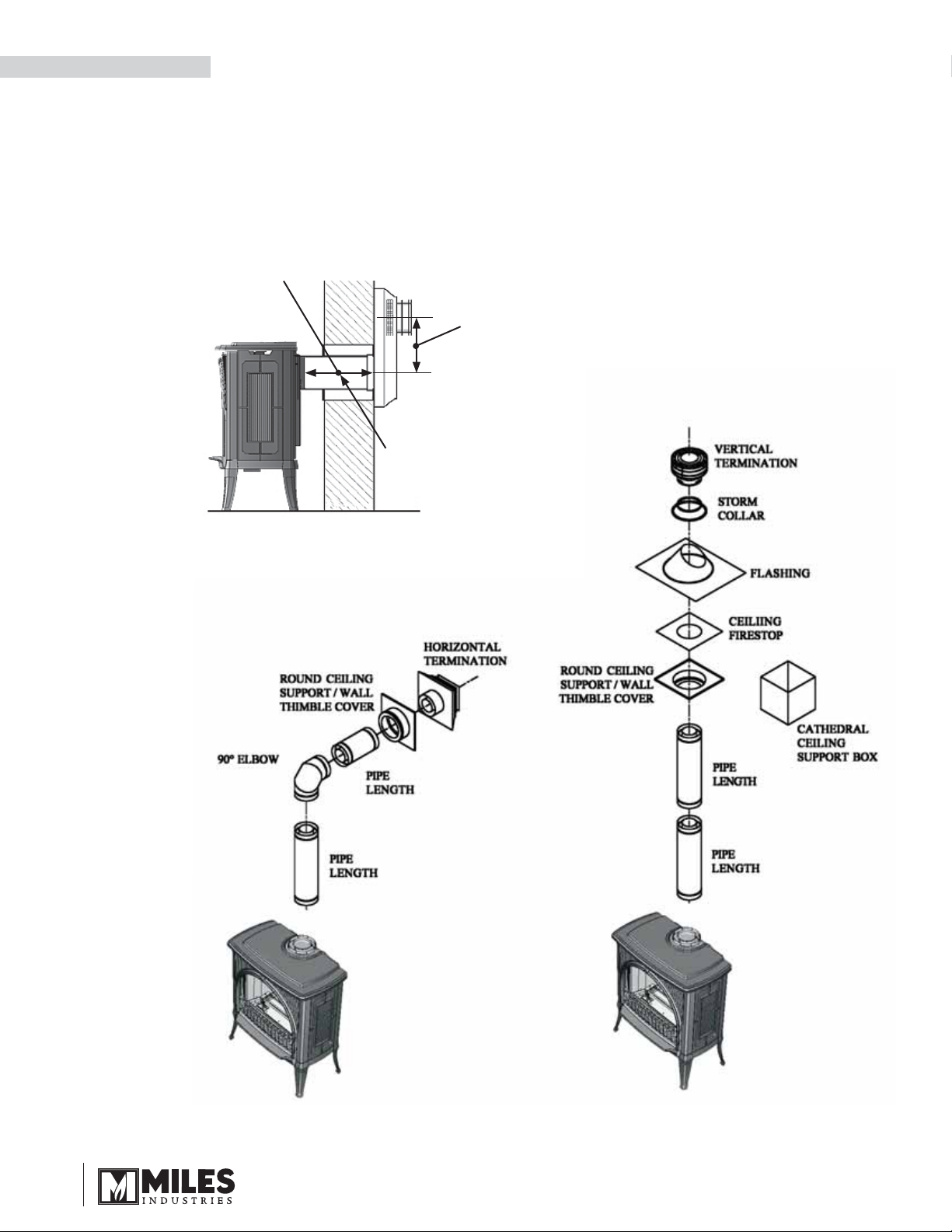
Typical Venting Components
See list of approved venting pipes and accessories on
pages 37–38.
Maximum pipe length:
24” (straight out with snorkel)
14” (45° elbow out with snorkel)
No more than one 45°
elbow allowed
Snorkel required (min.
14” high) with horizontal
run through the wall
(no rise)
Through wall (without vertical rise)
12
Through wall (with vertical rise) Through roof
Venting
INSTALLATION
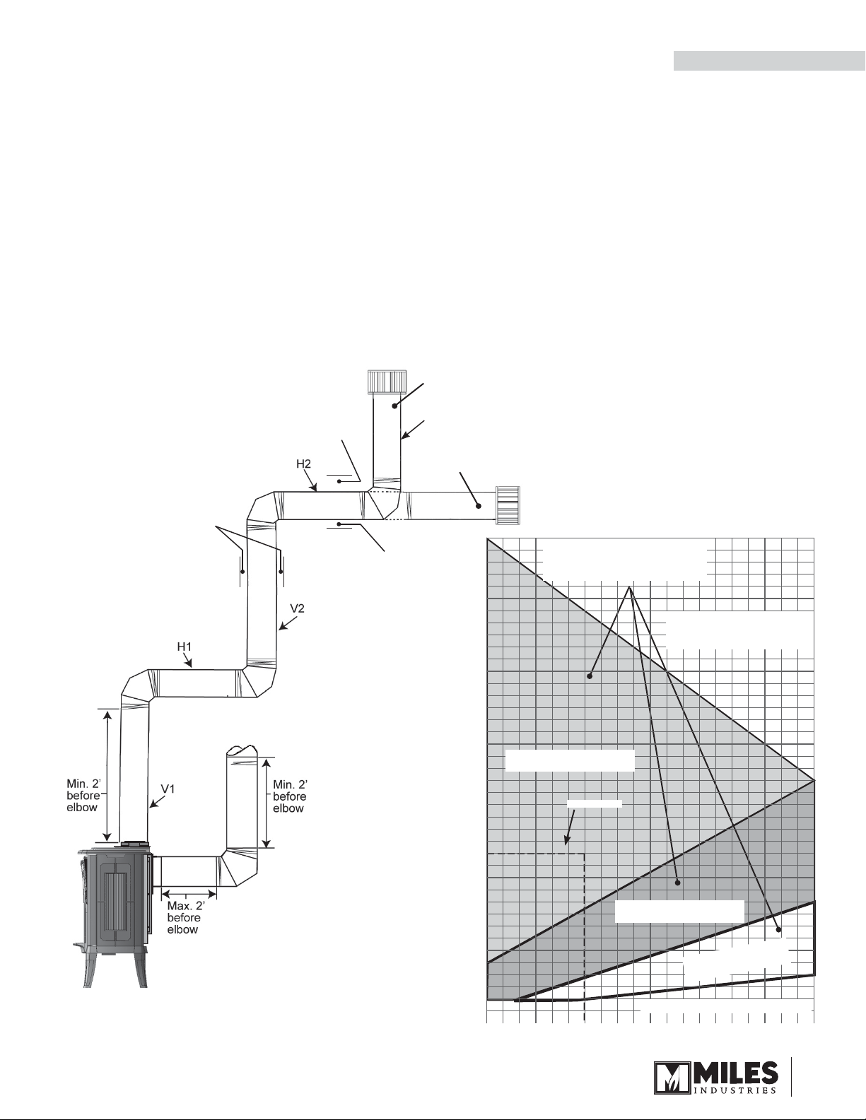
How to Read the Venting Chart
The chart below applies to top or rear outlet, roof or
wall termination with a vertical rise.
All rear outlet venting without a vertical rise must
be terminated by a snorkel.
1. The total length of the vent pipe cannot exceed 40
feet (12.2 m).
2. The minimum vertical height with roof termination is 8
feet (2.45 m).
3. Any combination of rise and run can be used as long
as they are within the allowable limits shown on the
chart below.
3” clearance
to combustible
above
horizontal pipe
1” clearance
to combustible
around vertical
pipe
1” clearance
to combustible
at bottom
and sides of
horizontal pipe
4. A maximum of 5 x 90 degrees elbows or equivalent (2
x 45 degrees = 90 degrees) can be used.
5. Each 90 degrees elbow installed on the horizontal
plane is equivalent to a 3 feet horizontal pipe;
therefore, 3 feet must be subtracted from allowable
horizontal run.
(45 degrees elbow is equivalent to 18 inches horizontal
pipe.)
6. All horizontal pipe runs must be graded 1/4 inch per
foot upwards in the direction of the exhaust fl ow.
7. Co-linear rear venting in existing chimney systems is
limited to 40 feet vertical rise.
8. Restrictors are not required for co-linear
installations.
Roof termination
V3
Wall termination
5 x 90º ELBOWS
MAXIMUM
40
38
36
34
32
30
Allowable Vent
Confi gurations
NO
INSTALLATION
Not to scale
Example 1
V Value = V1 (6’) + V2 (6’) + V3 (2’)= 14’
H Value = H1 (3’) + H2 (3’) = 6’
75% restrictor required
28
26
24
22
20
18
16
14
VERTICAL RISE
12
10
8
6
4
2
Restrictor 75
Example 1
Restrictor 50
NO
RESTRICTORS
NO INSTALLATION
2 4 6 8 10 12 14 16 18 20
HORIZONTAL RUN
13
INSTALLATION
Venting
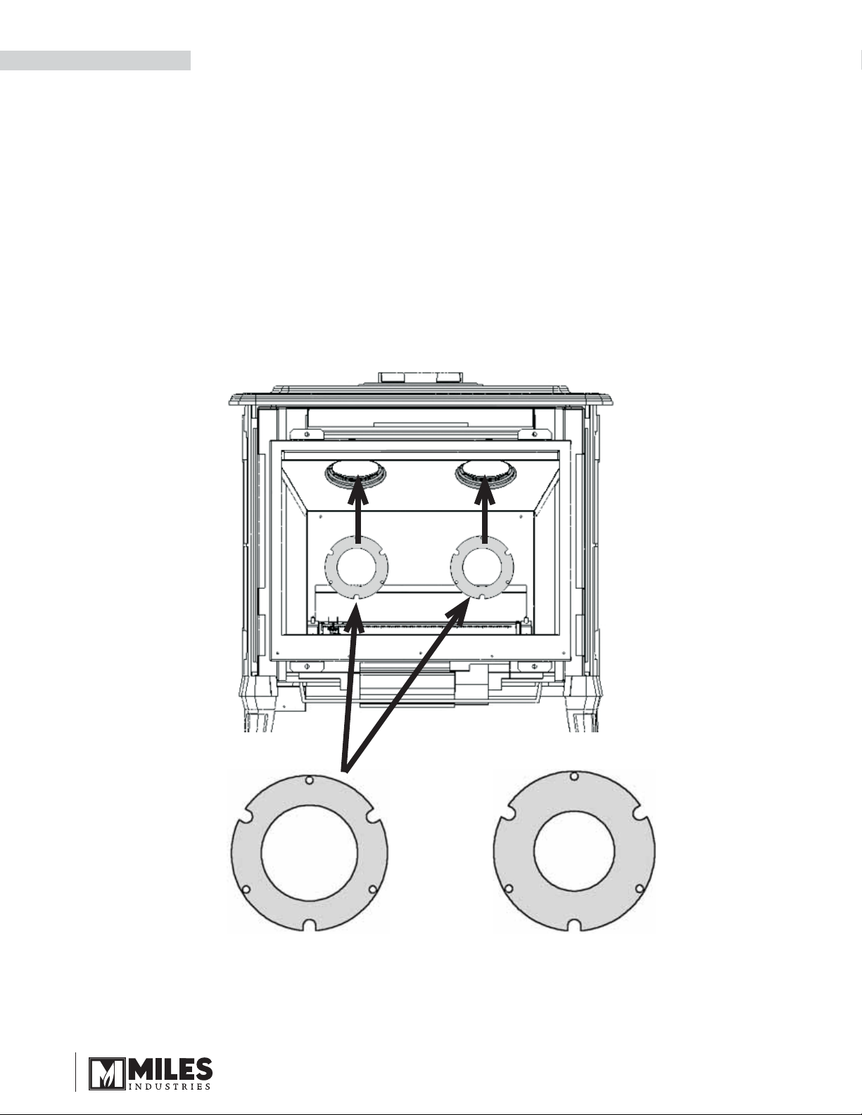
Restrictors
SOME INSTALLATIONS REQUIRE RESTRICTORS.
For improved fl ame picture and performance, this unit
is supplied with two different sets of vent restrictors.
The level of restriction required depends on the vertical
rise in the venting system and, to a lesser degree, the
horizontal run and number of elbows.
The amount of restriction is based on laboratory tests.
The ideal restrictor position may vary slightly, especially
when the vent pipe length is near the limits of the
acceptable confi gurations for each type of restrictors.
The chart on the previous page shows the vent
restrictor required relative to the length of the vent pipe.
Restrictors are not required for co-linear applications.
To install restrictors:
1. Remove every second screw from the exhaust ports
in the top of the fi rebox.
2. Install the restrictors with the removed screws.
14
50
75
OR
Restrictor 50 Restrictor 75
 Loading...