

LINEAR SERIES
LDK Linear Duct Kits
CSA approved for use with Valor Linear Models 1500J, 1700J & 1800J Heaters ONLY
Installation Instructions
for LDK1, LDK2, LDK3, LDK4, LDK5 & LDK6 Kits
Note: This kit must be installed by a qualifi ed
installer, service agency or gas supplier at
the time of the heater installation. These
instructions are to be used in conjunction with
the fi replace main installation instructions.
Application
This optional convection duct kit redistributes the warm
air fl ow away from the fi replace opening to a more
desirable location using natural convection without
use of a fan. The warm air fl ow may be relocated to
a position higher up the wall, out the sidewalls, or
even to another room. The result is much cooler wall
temperatures above the fi replace opening for locating
televisions, artwork, etc.
The 1595CFK Circulating Fan Kit is not recommended
when installing the LDK Linear Duct Kit.
Any kit, LDK1, LDK3 or LDK4 may be used with any of
the listed model fi replaces.
As a further option, the warm airfl ow may be extracted
away from the duct kit plenum (LDK1 and LDK4 ONLY)
by connecting a 1270RBK Remote Blower Kit to the
duct kit plenum.
This kit is compatible with the “J” series Linear
fi replaces only. Earlier version fi replaces will not accept
the addition of this kit.
Note: These instructions are to be used in conjunction
with instructions supplied with the fi replace.
fi replace requires the removal of the internal
convection baffl e for this system to function
properly—read instructions carefully.
The use of this kit will permit lower mantel clearances
to be used—see page 9. These lower mantel
clearances must only be used when the LDK Duct
system is installed.
Note, the
Approvals
The LDK1, LDK3, LDK4 duct kits are CSA approved
for use only with Valor Linear Series fi replaces listed
above—DO NOT use with any other models.
5-inch diameter duct (not supplied) used with this
kit must be metal and meet requirements of UL-181
Class 1 Air Duct. Flexible aluminum duct is acceptable
provided it meets the UL-181 Class 1 requirements.
Kits
There are 3 kits to choose from:
• LDK1—48” Plenum
• LDK3—14” Plenums (2), includes grilles
• LDK4—38” Plenum
Optional accessories
• LDK2—48” Finishing Frame, to use with LDK1
• LDK5—38” Finishing Frame, to use with LDK4
• LDK6— 5” dia Aluminum 2-ply Flex Kit—
2 x 10’–0” lengths, may be cut to required length
DO NOT cover or place objects in front
of the air outlet(s).
Minimum clearance below the ceiling is 2-1/2”.
Note that staining or streaking may occur on
light colored ceilings due to any dust, etc. in air
fl ow; placing the plenum(s) lower on the wall
will help reduce the possibility of staining or
streaking.
INSTALLER
Leave this manual
with the appliance.
CONSUMER
Retain this manual
for future reference.
WARNING
!
WARNING
!
4005484-02
© Copyright Miles Industries Ltd., 2016.
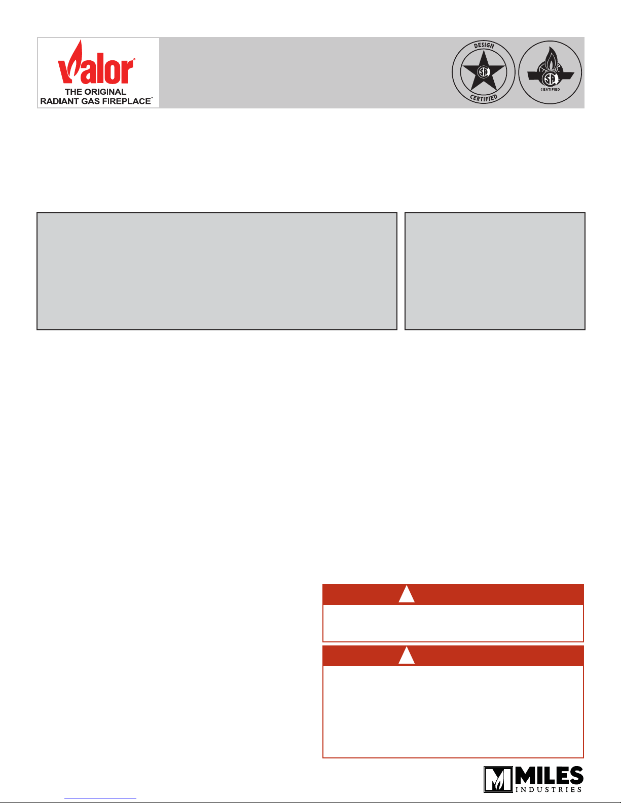
Kits Contents
LDK1
48” x 2”
LDK4
38” x 2”
LDK2 (supplied separately)
48” frame
4 take-off
collars included
LDK3
2 - 14” x 6”
4 take-off
collars included
LDK6
2 - 10’ x 5”
LDK5 (supplied separately)
38” frame
4 take-off
collars included
2 - 14” x 6”
grilles included
2

Suggested Confi gurations
WARNING
!
This duct kit is approved for horizontal
discharge ONLY. DO NOT install ple-
num in fl oor or ceiling.
DO NOT DISCHARGE OUTDOORS.
Front wall outlet using LDK1 or LDK4
Rear wall outlet using LDK1 or LDK4
Note: Fireplace vent may confl ict with
plenum. Offset vent around plenum.
Side wall outlets using LDK3
Rear wall outlets using LDK3
Corner installation with front or rear wall outlet
using LDK1, LDK3 or LDK4
3
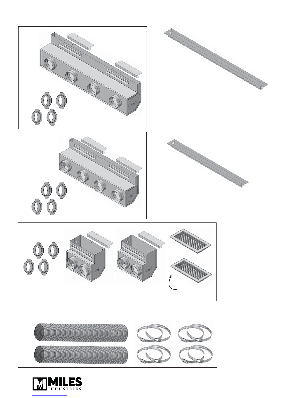
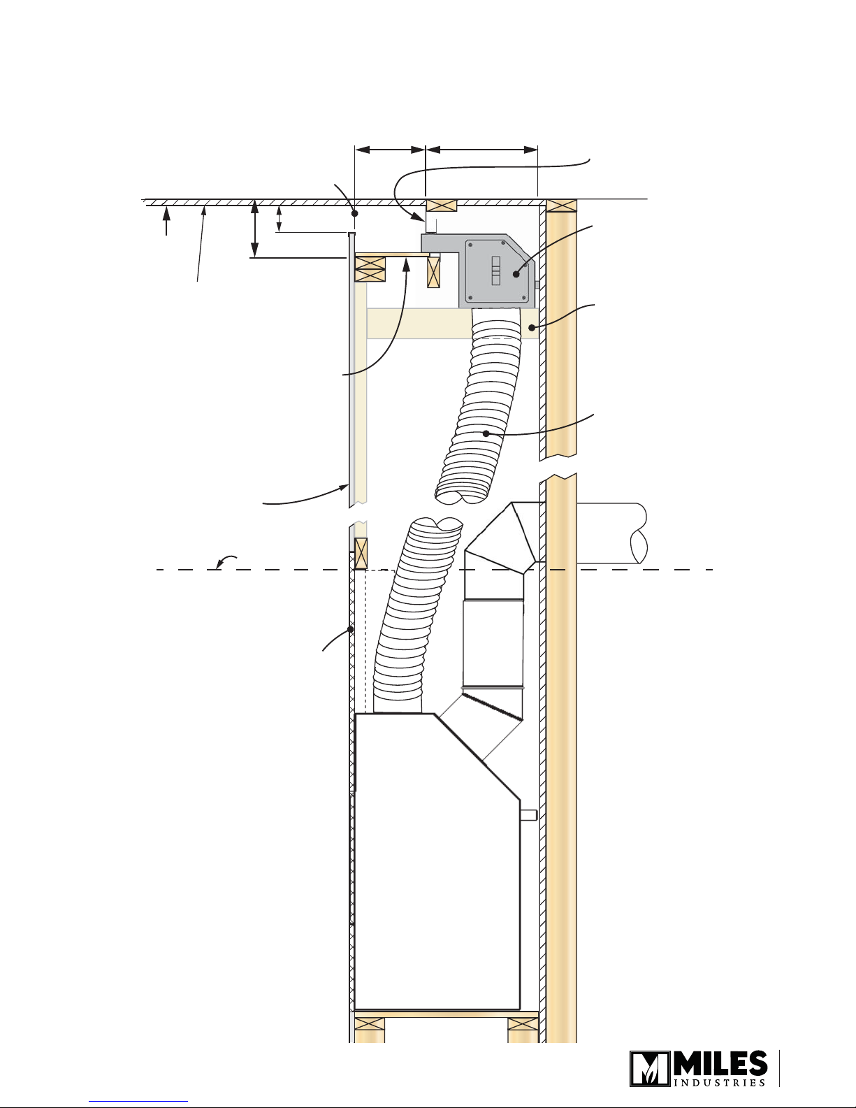
Overview (applies to all kits)
Ceiling
Flexible or rigid,
5” diameter
UL-181, Class 1
Air Duct (4)
(use LDK6 kit
or equivalent)
Min. 1”
clearance to
combustibles
around pipe
Min. 2-1/2”
clearance
to ceiling
8-1/2”
14-1/2”
9-3/8”
Min. 30”, Max. 12’-0”
See table for osets
32-3/8”
Y
Vertical Rise
30” 24”
36” 36”
42” 48”
48” 60”
54” 72”
60” 84”
66” 96”
12’-0” 96” Max.
Max. Allowable
Horizontal
X
Offset
Support horizontal
sections of pipe using
strapping every 24”
5”
Min. bend
+
radius
Top of replace
LDK 1, LDK 3 or LDK 4
8”
Min. bend
radius
+
5”
4
12
DO NOT RUN
pipe horizontal.
Minimum slope 4:12
Min. 2-1/2”
clearance
to ceiling
Min. 1”
clearance to
combustibles
around pipes
Ceiling
Vertical Rise
‘Y’
(Min. 30”
Max. 12’-0”)
Maximum allowable Horizontal Oset
4
‘X’
(oset for take-o
that’s furthest away)
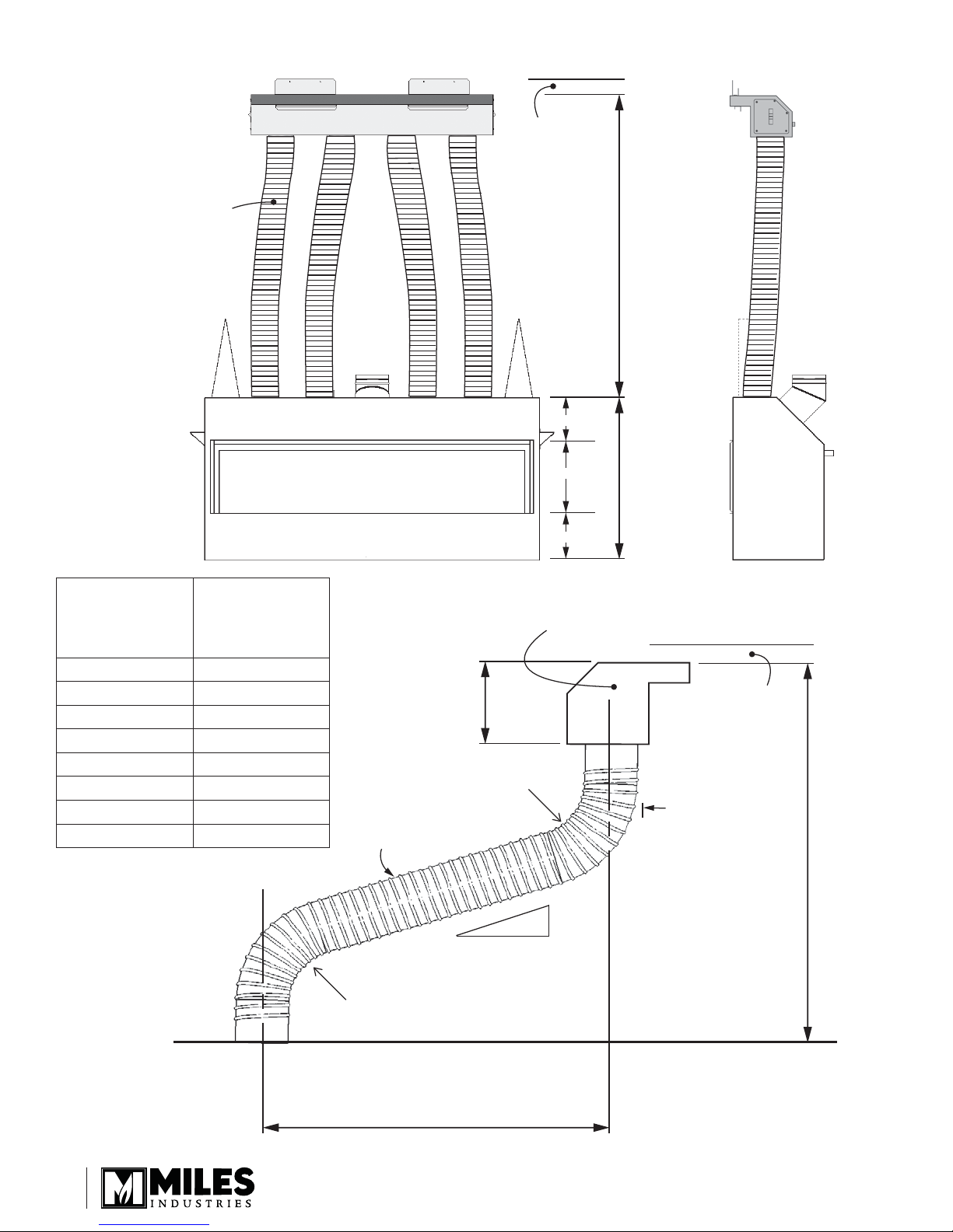
Dimensions
LDK 1
LDK 4
LDK 3
5” dia.
collars (4)
12” LDK 1
5” dia.
collars (4)
48” LDK 1
C
L
12” LDK 1 12” LDK 1
38” LDK 4
C
L
10” LDK 4 10” LDK 4 10” LDK 4
14”
C
1/2” wallboard
11-1/2”
mounting
bracket and
3”
2”
mounting
bracket and
1/2”
stando
3”
1/2”
stando
L
3”
1/2” stando
2”
mounting
bracket and
1/2” stando
1-1/2” stando
8”4”
1/2” wallboard
11-1/2”
mounting
bracket and
1-1/2” stando
8”4”
1/2” wallboard
11-1/2”
mounting
bracket and
1-1/2” stando
1/2”
standos
8”
6” knock-out
each end for
optional
1270RBK
connection
1/2”
standos
8”
6” knock-out
each end for
optional
1270RBK
connection
1/2”
standos
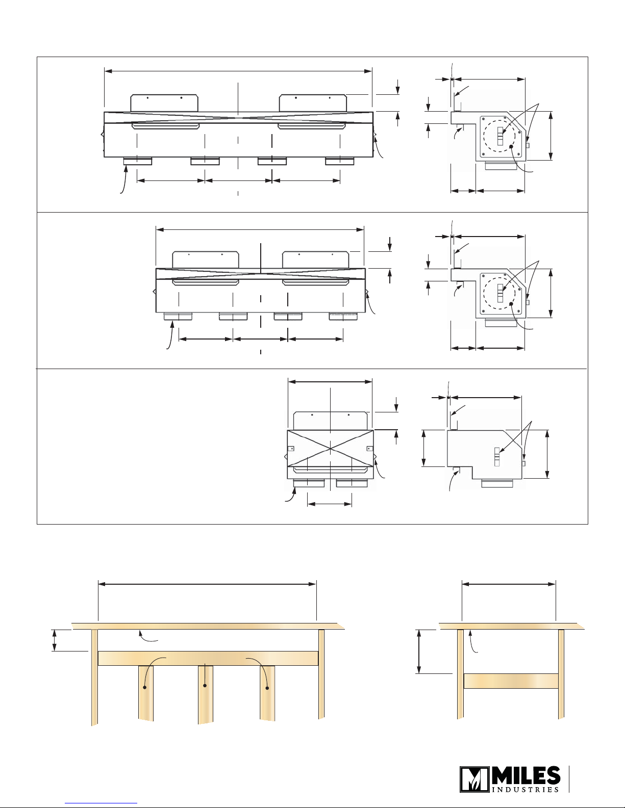
Rough Frame Openings
4”
Min. 1” below nished ceiling
LDK 1 = 49”
LDK 4 = 39”
Framing on edge
5” dia.
collars (2)
6”
1/2”
stando
7”
mounting
bracket and
1/2” stando
8”
LDK 3 = 15”
8”
Min. 1” below
nished ceiling
Framing on edge
LDK 1 & LDK 4 LDK 3
5

Framing and Clearances
Rough Frame Opening
LDK 1 = 49”
LDK 4 = 39”
LDK 3 = 15”
See detail
LDK 1 = 4”
LDK 4 = 4”
LDK 3 = 8”
See Installation
Manual packed
with appliance
for minimum
combustible
cavity dimensions
Rough
Frame
Opening
2 x 4 on edge
2 x 4 on edge
Framing on edge
Min. 1/2”
clearance to
combustibles
at ends
20” min.
LDK 1 & 4
4”
LDK 3
8”
Framing
“on edge”
Framing
“on edge”
Min. 2-1/2” clearance to ceiling
Ceiling
1/2”
Min. 2-1/2” clearance to ceiling
Ceiling
1/2”
1-1/2” min. clearance
to combustibles (top)
1/2” min.
clearance to
combustibles
rear & sides
2 x 4 on edge
to support
plenum.
Maintain 1”
clearance
to pipes
1” min.
clearance to
combustibles
all around pipes
1-1/2” min. clearance
to combustibles (top)
1/2” min.
clearance to
combustibles
rear & sides
1” min.
clearance to
combustibles
all around pipes
6
Alternate Discharge Opening Using Valance Gap At The Top Of Wall
Minimum length
of opening
L1 - 1500 = 40”
L2 - 1700 = 50”
L3 - 1800 = 64”
2-1/2” min.
5-1/2”
Ceiling
Note: Staining or streaking may occur
on light colored ceilings due to any
dust, etc. in air ow. Maximizing the
opening size will help reduce any
staining or streaking.
Discharge cavity requires a base the
entire length of the plenum outlet
as a minimum otherwise beyond
that it may be left open to allow
cavity to ventilate and mix with
discharge air.
Combustible wall
construction
Min. 8” Min. 12”
Space between mounting brackets
may be left open to allow cavity
to ventilate.
LDK 1 & LDK 4 ONLY see clearances on page 6
2 x 4 on edge to support
plenum. Maintain 1”
clearance to pipes.
Min. 1” clearance
around pipes
Top of stand-os
See installation manual packed
with appliance for minimum
combustible cavity dimensions
Non-combustible
cement board
7

Linear Duct Kit LDK 1, LDK 4 with optional 1270RBK Remote Blower Kit
Universal take-o supplied with 1270RBK kit.
Can mount to either end of plenum.
Maximum 1 x 1270RBK kit per plenum.
Note: DO NOT CONNECT 1270RBK directly
See installation instructions packaged
with the LDK Linear Duct Kits
LDK1 or LDK4 plenum
to replace when using LDK Duct Kit;
connect to LDK plenum ONLY as this will
ensure cooler wall temperature whether or
not the 1270 fan is running.
5” dia. piping
Linear 1500J, 1700J or 1800J replaces
8
1270RBK fan unit see diagram for
possible mounting
positions. May be
positioned higher
or lower than
LDK plenum position.
 Loading...