

Installation Manual
Direct Vent Zero Clearance
Gas Fireplace
natural gas 1700KN
propane gas 1700KP
L2
Installer: Leave this manual with the appliance.
Consumer: Retain this manual for future reference.
WARNING:
FIRE OR EXPLOSION HAZARD
Failure to follow safety warnings
exactly could result in serious
injury, death, or property damage.
Do not store or use gasoline or other
fl ammable vapors and liquids in the
vicinity of this or any other appliance.
WHAT TO DO IF YOU SMELL GAS
▪ Do not try to light any appliance.
DANGER
Hot glass
will cause burns.
Do not touch glass
until cooled.
Never allow children
to touch glass.
▪ Do not touch any electrical switch; do
not use a
▪ Leave the building immediately.
▪ Immediately call your gas supplier from
a neigh
supplier’s instructions.
▪ If you cannot reach your gas supplier,
ll the fi re department.
ca
Installation and service must be
performed by a qualifi ed installer, service
agency or the gas supplier.
A barrier designed to reduce
the risk of burns from the hot
viewing glass is provided with this
appliance and must be installed for
the protection of children and
other at-risk individuals.
ny phone in your building.
bor’s phone. Follow the gas
4008056-01
©2019, Miles Industries Ltd.

This appliance may be installed in an
after-market permanently located,
manufactured (mobile) home where
not prohibited by local codes. This
appliance is only for use with the type
of gas indicated on the rating plate.
This appliance is not convertible for
use with other gases, unless a certifi ed
kit is used.
INSTALLER: Leave this manual with the
appliance.
This manual contains instructions to
install the ENGINE ONLY. A trim kit is
REQUIRED to complete the installation.
A barrier screen is provided with the
trim kit. Refer to the manual supplied
with the trim for installation.
This appliance is a domestic roomheating appliance. It must not be used
for any other purposes such as drying
clothes, etc.
CONSUMER: Retain this manual for
future reference.
Massachusetts:
The piping and fi nal gas connection must be
performed by a licensed plumber or gas fi tter
in the State of Massachusetts. Also, see Carbon
Monoxide Detector requirements in the fi replace
installation manual.
WARNING
This product can expose you to chemicals
including Benzene, which is known to the State
of California to cause cancer and birth defects or
other reproductive harm. For more information
go to www.P65Warnings.ca.gov.
Note: Natural gas, in its original state, contains
Benzene.
This appliance is suitable for
installation in a bedroom or bed
sitting room.
Ce guide est disponible en français sur demande.
Valor Fireplaces
190–2255 Dollarton Highway
North Vancouver, BC, Canada V7H 3B1
T 604.984.3496 F 604.984.0246
valorfi replaces.com
2
The information contained in this manual is believed
to be correct at the time of printing. Miles Industries
Ltd. reserves the right to change or modify any
information or specifi cations without notice. Miles
Industries Ltd. grants no warranty, implied or stated,
for the installation or maintenance of your heater,
and assumes no responsibility for any consequential
damage(s).
© Copyright Miles Industries Ltd., 2019. All rights reserved.
Designed and manufactured for Miles Industries Ltd.

Welcome to Valor
®
This appliance has been professionally installed by:
Dealer Name: ________________________________
Phone:______________________________________
Fireplace Safety ................................................. 4
Specifi cations ..................................................... 6
Kits & Accessories .............................................. 7
Dimensions & Location ..................................... 8
Installation Planning ......................................... 9
Before Installing ............................................................9
Overview ......................................................................10
Mantel Clearances ......................................................11
Framing .........................................................................13
Wall Finish ....................................................................16
Material Specificat ions ..............................................16
Non-Combustible Cement Board ............................16
Avoiding Cracking Wall Finishes ...............................18
Venting .............................................................. 19
Overview ......................................................................19
Co-Axial ....................................................................... 20
Typical Co-axial Venting Components ....................20
Venting Chart ..............................................................21
Restrictor Settings .....................................................22
Horizontal Vent Termination ....................................23
Vertical Vent Termination .........................................24
Co-Linear Conversion ................................................ 25
Installation into existing fireplace cavity ................25
Installation partially into fireplace cavity ...............26
Installation into existing adjacent chimney ...........27
Example of co-linear conversion accessories........28
Installation ....................................................... 29
Appliance Preparation .............................................. 29
Unpack Appliance ......................................................29
Fit Standoffs ................................................................29
Remove Heat Shield ...................................................29
Convert from Top to Rear Outlet (if required) .......30
Fit Appliance into Framing ........................................31
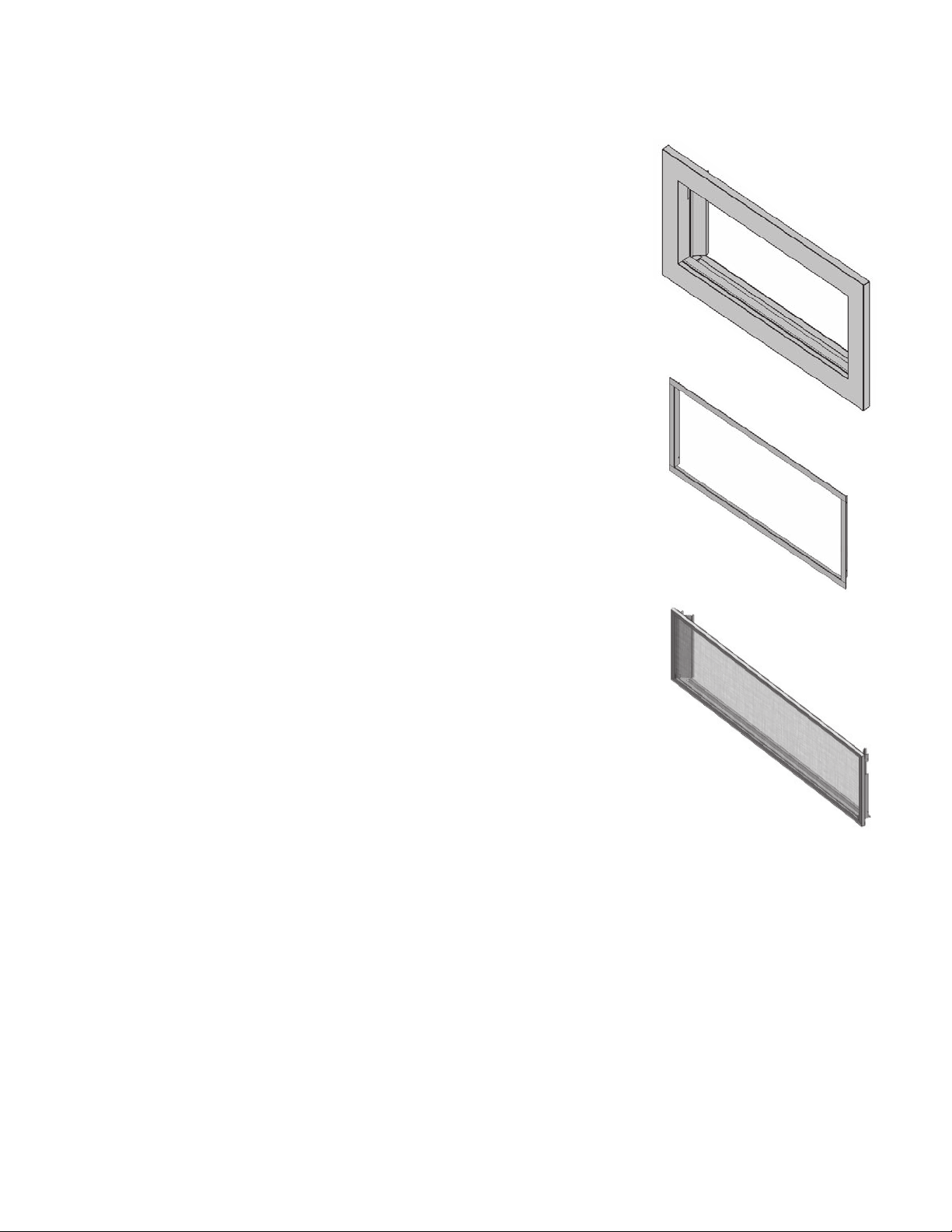
Remove Window ........................................................32
Please read this manual BEFORE
installing and operating this
appliance.
HeatShift™ System—if used .................................... 33
Install HeatShift Take-Off Collars to Appliance .....33
Remove Convection Baffle .......................................33
Electrical Wiring ......................................................... 34
Gas Supply ................................................................... 36
Liners ........................................................................... 38
Fuel Beds ..................................................................... 40
Driftwood Kit 1705DWK ........................................... 40
Decorative Glass Murano 1700DGM.......................43
Rocks & Shale Set 1714RSS ...................................... 44
Split Wood Kit 1700SWK ............................................47
Birch Log Kit 1700BLK ................................................50
Window Re-Installation & Checking ....................... 53
Wall Switch .................................................................. 54
Remote Control Pairing ............................................. 56
Checking Operation and Aeration .......................... 58
Trim & Barrier Screen ................................................ 59
Wiring Diagram ................................................ 60
Approved Venting Components .................... 61
Commonwealth of Massachusetts ............... 63
Appendix A—Lighting Instructions ............... 65
Appendix B—Remote Control Operation .... 66
Appendix C—Wall Switch Operation ............73
Appendix D—HeatShift™System .................. 74
Appendix E—Spare Parts ............................... 94
3

Fireplace Safety
This manual contains very important information about the safe installation and operation of the fi replace. Read and
understand all instructions carefully before installing and operating the fi replace. Failure to follow these instructions
may result in possible fi re hazard and will void the warranty.
Replacement manuals are available by contacting the Valor Customer Service at 1-800-468-2567, or by visiting
valorfi replaces.com.
WARNING: Extremely Hot!
Heat and fl ammability
• Some parts of the fi replace are extremely hot, par-
ticularly the glass windows. Use the barrier screens
provided or a gate to reduce the risk of severe burns.
• The glass windows can exceed 500°F (260°C) at full
capacity.
• Always keep the appliance clear and free from combustible materials, gasoline, and other fl ammable
vapors and liquids.
• Be aware of hot wall surfaces! The walls directly above
the fi replace can get very hot when the fi replace
heats. Although safe, it may reach temperatures in excess of 200ºF (93°C) depending on choice of optional
accessories. Do not touch!
• Be aware of hot hearth/fl oor surfaces! Any projections
directly around the fi replace can get very hot when
the fi replace heats. Although safe, they may reach
temperatures in excess of 200ºF (93°C)depending on
elevation of hearth. Be careful of touching these! Temperature of projection surfaces will be reduced when
barrier screens are installed.
• Some materials or items, although safe, may discolor,
shrink, warp, crack, peel, and so on because of the
heat produced by the fi replace. Avoid placing candles,
paintings, photos and other combustible objects
sensitive to heat or furniture within 36 inches (0.9m)
around the fi replace.
)LUHSODFH
Hearth
Do not put
furniture or other objects
in this space in front of
WKHȴUHSODFH
36” [0.9 m]
• Any safety screen, guard, or barrier removed for servicing an appliance must be replaced prior to operating the appliance.
• Children and adults should be alerted to the hazards
of high surface temperature and should stay away to
avoid burns or clothing ignition.
• Young children should be carefully supervised when
they are in the same room as the appliance. Toddlers,
young children, and others may be susceptible to
accidental contact burns. A physical barrier is recommended if there are at-risk individuals in the house. To
restrict access to a fi replace or stove, install an adjust-
able safety gate to keep toddlers, young children, and
other at-risk individuals out of the room and away
from hot surfaces.
• Due to its high temperatures, the appliance should be
located out of traffi c areas and away from furniture
and draperies.
4
• A barrier designed to reduce the risk of burns from
the hot viewing glass is provided with this appliance
and shall be installed for the protection of children
and other at-risk individuals.
• Clothing or fl ammable material should not be placed
on or near the appliance.

Fireplace Safety
Glass windows
WARNING
Do not operate this appliance with the
glass front removed, cracked, or broken.
Replacement of the glass front should
be performed by a licensed or qualified
service person. Do not strike or slam the
glass front.
• The glass front assemblies must be in place and
sealed before the unit can be placed into safe
operation.
• The glass front assemblies must only be replaced as
complete units, as supplied by the fi replace manufac-
turer. No substitute material may be used.
• Do not use abrasive cleaners on the glass front assemblies. Do not attempt to clean the glass when
it is hot.
Intended use
• This appliance is designed and approved as a supplemental heater and provides the potential for most
energy conservation when used while attended. The
use of an alternate primary heat source is advisable.
• This unit is not for use with solid fuel.
• Do not use this heater as a temporary source of heat
during construction.
Installation and Servicing
• Installation and repair should be done by a qualifi ed
service person. The appliance should be inspected
before use and at least annually by a professional
service person. More frequent cleaning might be
required due to excessive lint from carpeting, bedding
material, et cetera. It is imperative that control compartments, burners, and circulating air passageways
of the appliance be kept clean.
Venting
• This unit must be used with a vent system as described in this manual. No other vent system or components may be used.
• Never obstruct the fl ow of combustion and ventilation
air. Keep the front of the appliance clear of all obstacles and materials for servicing and proper operation.
• This gas fi replace and vent assembly must be vented
directly to the outside and must never be attached to
a chimney serving a separate solid fuel burning appliance. Each gas appliance must use a separate vent
system. Common vent systems are prohibited.
WARNING
Side outlets
Ceiling outlet
Front outlet
HeatShift
System:
Do not cover
or place items
in front of or
above outlet(s)!
5

Specifications
Approval & Codes
This appliance is certifi ed to ANSI Z21.88-2017/CSA
2.33-2017 American National Standard / CSA Standard
for Vented Gas Fireplace Heaters for use in Canada
and USA, and to CGA 2.17-91 High Altitude Standard in
Canada. This appliance is for direct vent installations.
This appliance complies with CSA P.4.1-15 Testing
method for measuring annual fi replace effi ciencies.
The installation must conform to local codes or, in
the absence of local codes, with the National Fuel
Gas Code, ANSI Z223.1/NFPA 54 or the Natural Gas
and Propane Installation Code CAN/CGA-B149.1. Only
qualifi ed licensed or trained personnel should install
this appliance.
This appliance must be electrically grounded in
accordance with local codes, or, in the absence of local
codes, with the National Electrical Code, ANSI/NFPA 70
or the Canadian Electrical Code, CSA C22.1.
Ratings
Model 170 0KN 1700KN
Gas
Altitude (Ft.)*
Input Maximum (Btu/h)
Input Minimum (Btu/h)
Manifold Pressure (in w.c.)
Minimum Supply Pressure (in
w.c.)
Maximum Supply Pressure (in
w.c.)
Main Burner Injector Marking
Pilot Injector Marking
Min. Rate By-Pass Screw
Natural Propane
0-4,500 feet*
36,000 36,000
21,000 22,500
4” 10”
5” 11”
10” 14”
DMS#32 DMS#49
51 3 0
220 160
*High Altitude Installations
Input ratings are shown in BTU per hour and are
certifi ed without deration for elevations up to 4,500
feet (1,370 m) above sea level.
For elevations above 4,500 feet (1,370 m) in USA,
installations must be in accordance with the current
ANSI Z223.1 and/or local codes having jurisdiction.
Heating value of gas in some areas is reduced to
compensate for elevation—consult your local gas
utility to confi rm.
For installations at elevations above 4,500 feet
(1,370 m) in Canada, please consult provincial and/or
local authorities having jurisdiction.
Supply Gas
Heater engine 1700KN uses
natural gas.
Heater engine 1700KP uses
propane gas.
The supply pressure must be
between the limits shown in the Ratings section.
The supply connection is 3/8” NPT male and located on
the left hand side of the fi rebox. A shut-off valve (not
supplied) is required on the supply line to isolate the
unit during service. See Gas Supply Installation section
for details.
X
Conversion Kits
The 1700K are supplied as natural gas or propane
gas and are fi eld convertible between fuels. See
instructions packaged with the conversion kits for
further information.
Electrical
The 1700K are designed to run on battery power and
do not require an electrical power source to operate
as a heater. However, they require electrical power
to operate optional 1595CFKV2 Circulating Fan Kit,
GV60WIFI WiFi Kit or 1270RBK Remote Blower Kit.
HeatShift™System
The 1700K are designed to allow the installation of the
optional HeatShift System, a convection system that
redistributes the warm air fl ow away from the fi replace
opening to a more desirable location using natural
convection, without use of a fan.
The warm air fl ow may be relocated to a position higher
up the wall, out the sidewalls, or even to another room.
The result is much cooler wall temperatures above the
fi replace opening for locating televisions, artwork, etc.
Please note that the framing and mantel clearances
are aff ected by the installation of the HeatShift
System. Refer to “Appendix D—HeatShift™System™” on
page 74 for more information.
Outdoor Conversion Kit
The 1700K models are supplied standard for indoor
applications and may be adapted for installation in
specifi c “outdoor” applications protected from weather
as defi ned in the GV60CKO outdoor conversion kit
manual.
6

Kits & Accessories
Required Kits Information accurate at the time of printing and subject to change
without notice.
Fuel Beds (choose one)
1705DWK Driftwood Kit
1700DGM Decorative Glass Murano Kit
1714RSS Rock & Shale Kit
1700SWK Split Wood Kit
1700BLK Birch Logs Kit
Liners Panels (choose one)
1715FBL Fluted Black Liners
172 5RGL Re fl ective Glass Liners (requires 1725RGL-3 Glass Retainer Kit)
1735LML Limestone Liner Set
1740SSL Stacked Stone Liners
Trims (choose one) Barrier Screen
1730CIK Clean Install Kit - Fine Mesh - REQUIRES HeatShift 4007675
1750v2 Linear 3-1/2” Surrounds 4004221
1775LFB Linear 1” Finishing Trim Black 4005562
Optional Accessories
Information accurate at the time of printing and subject to change
without notice.
Gas Conversion Kits
1700KNGK Conversion to natural gas
1700KPGK Conversion to propane gas
Other Accessories
GV60WIFI WiFi kits - REQUIRES GV60 V-module
GV60CKO Outdoor Fireplace Conversion Kit
1506DRK Additional rocks for Driftwood Kit
1595CFKV2 Circulating Fan Kit - REQUIRES GV60 V-module
1270RBK Remote Blower Kit
LDK HeatShift System Kits (gravity fl ow) - MANDATORY with 1730CIK
Hearth Gate
Hearth gates such as Cardinal’s VersaGate are available at retail stores carrying
safety products for children.
WARNING
HeatShift System MUST be installed on
this appliance when using 1730CIK—Clean
Installation Kit!
WARNING
Optional electrical accessories ARE NOT
ALLOWED when adapting appliance for
outdoor use.
7
i
[
]
p
f
[
]
f
r
Electrical
I
t
G
A
t
Z
6WDQG2V
r
C
r
Li
.
g
ȴ
e
f
t
C
t
H
q
r
t
app
57-3
]
]
6”
]
1
6”
]
[383
18
2”
[470
]
3-3/4”
[9
]
”
[10
m]
8
0
]
3
8
[822
]
8
[8
]
2
[369 m
m]
9-3/8”
[238 m
m]
52” [ 132
]
262
]
1270
B
(
H
p
1270
e
(
Zero Clearance
WR6WDQGRV
DW%DFNDQG6LGHV
Zero Clearance
DWEDFNFRUQHUV
88” [2235 mm]
20-1/2”
[519 mm]
Ze
ro Clearance
DW
EDFNFRUQHUV
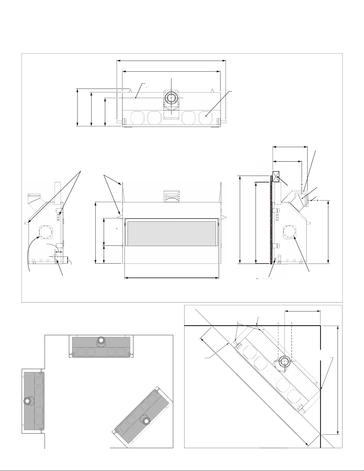
Dimensions & Location
Dimensions
4
2 m
”
-7/
5 mm
5
ero Clearance
457 mm
mm
”
/
-
5-1/1
14-1/
mm
/4” [ 1467 mm
1 mm
ente
ne
Top V iew
eatShift System
outlets (remove
1130 mm
1092 mm
cement board
o
n. 44-1/2”
to to
M
Min. 43”
lates)
heade
underside o
5-1/1
-1/
mm
mm
Heade
eat shield
re
uired fo
rear ven
outlet
lications
6-5/8” dia
Ventin
HOG
convertibl
rom top to
rear outle
enter of ven
41 mm
”
-1/
Blower Kit outlet
remove plate)
Location
8
RBK Remot
5 mm
as Line
ccess Poin
49-11/16” [ 1
mm
nlet Poin
Front ViewLeft Side View Right Side View
Corner Dimensions
RBK Remote
lower Kit outlet
remove plate)

Installation Planning
Caution
Only qualified, licensed, or trained personnel
should install this appliance.
1. YOU NEED TO KNOW FROM THE HOMEOWNER:
• Will optional HeatShift System
• Height of appliance and shelf, if used;
• Thickness and type of wall fi nish around
appliance;
• Trim used
• Other optional accessories used (if any);
• Venting confi guration.
2. Unpack the appliance, removing all items packed
inside and around it. Recycle the packaging.
3. Check that you have everything, using the Pack Content sheet. Also, check that you have:
• Fuel bed (packed separately);
• Liner panels (packed separately);
• Remote Battery and Wall Switch Kit;
• HeatShift System components (if used);
• Gas conversion kit (if necessary);
• Venting accessories;
• Electrical accessories (if used).
4. Carefully read the Installer’s Checklist included with
the fi replace for the installation sequence.
*
;
*
be used;
Before Installing
WARNING
*
HeatShift System MUST be installed on
this appliance when using 1730CIK—Clean
Installation Kit!
9

ndPlate
ept
ard
d
im.730
f
t.
im.
e
ard
.
in
is
Any
k
pag
pg
pg
e p
p
p
age
g
g
g
.
Installation Planning
Overview
Note: This appliance may be installed in outdoor, weather protected environments as defi ned in the GV60CKO
Outdoor Conversion Kit instruction manual.
Mantel—See Mantel & Hearth Clearances
Framing—See Framing Requirements
rrou
ith Barrier Screen
required)
Nar
ow 1” Trim 1775LFB and
wid
r 3-1/2” steel Trim 1750
table, acc
on-combustible finish over
Cement board finishes up to
Not
173 0 C I K in s tal l s befor
wall finishes applied
ver cement board must
be non-combustible.
Combustible mantel are o
rovided they conform to
chart on
additional
cement
behind tr
CIK’s narrow trim
uires HeatShi
imeter of tr
cement
an
11
1/2 inch thick non-combustible cement board –NOT supplied
Supplied as vertical outlet, fi eld convertible to horizontal
outlet. Note - Vertical rise required in vent system
Optional HeatShif t System
outlets (4)—Required with
173 0C IK
170 0 K hea t er
Remote Battery
and Wall Switch Kit
(required) (35-foot wire
length) (supplied)
Remote
Handset
Wall Holder
Electrical
junction box
(not supplied) to
connect power
when using
optional fan, WiFi
Combus tible Floor
Hearth: not required.
If used, must be minimum 4”
below fi replace opening unless
using HeatShift (see “Appendix D—
HeatShift™System” on page 74)
WARNING
Some materials or items, although safe,
may discolor, shrink, warp, crack, peel,
and so on because of the heat produced
by the fireplace. Avoid placing candles,
paintings, photos, and other items
sensitive to heat around the fireplace.
10
Combustible Framing Allowed Beneath Fireplace. When the appliance
is installed directly on carpeting, tile or other combustible material
other than wood fl ooring, the appliance shall be installed on a metal
or wood panel extending the full width and recessed depth of the
appliance.
WARNING
HOT WALL SURFACES! The wall directly
above the fireplace is constructed of noncombustible materials and, although safe,
it may reach temperatures in excess of
200°F (93°C) depending on choice of trims.
Do not touch. Finish wall using materials
suitable for these temperatures.

Installation Planning
Combustible Mantel—Left Side View
NOTE
Use for the optional HeatShift
System affects mantel and hearth
clearances. See HeatShift section in
Appendix D of this manual.
WARNING
HeatShift System MUST be installed
on this appliance when using
1730CIK—Clean Installation Kit!
(from Face of Cement Board)
0 2” 4” 6” 8” 10”12”
Mantel Projection
Mantel Clearances
Ceiling
44”
Mantel
42”
Height
(from
40”
38”
Bottom
of Unit)
24” Min. to Ceiling
Face of 1/2” thick
non-combustible
cement board
Fireplace
Opening
4” minimum to
combustible or
non-combustible hearth
Bottom of Unit
23-7/8”
Do not put
furniture or objects
within 36” (914 mm)
of front of appliance
9-3/8”
11

Installation Planning
Combustible Sidewall / Mantel Leg—Top View
Face of
Finished
Wall
Mantel Clearances
FIREPLACE
Fireplace Opening
49-11/16”
Wall
Min. 4” to
wall or
combustible
mantel leg
12
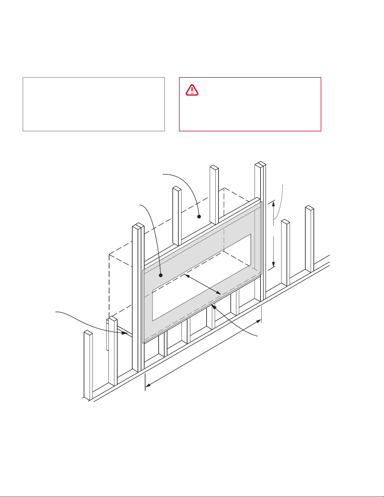
Installation Planning
Framing Dimensions
Framing
NOTE
Use fo the optional HeatShift
System affects mantel and hearth
clearances. See HeatShift section in
Appendix D of this manual.
NOTE: Height of cavity may be
DHFWHGE\YHQWFRQȴJXUDWLRQ
- see page 15
1/2” thick non-combustible
cement board required above,
on each side and below
engine opening (NOT supplied)
NOTE: This unit requires a
solid platform to support it.
Combustible framing allowed
EHQHDWKȴUHSODFH:KHQWKH
appliance is installed directly
on carpeting, tile or other
combustible material other
WKDQZRRGȵRRULQJWKH
appliance shall be installed
on a metal or wood panel
H[WHQGLQJWKHIXOOZLGWK
and recessed depth of the
appliance
WARNING
HeatShift System MUST be installed
on this appliance when using
1730CIK—Clean Installation Kit!
Between underside
of header and bottom
RIȴUHER[
43”
20”
57-3/4”
No hearth required.
If using a hearth,
see page 11.
13
Installation Planning
Framing with Partial Shelf—Top Outlet
15-1/16”
[383 mm]
Approx. 10-3/4”
[274 mm]
from back
surface of
ZDOOȴQLVKWR
front surface
of appliance
case w/no
YHQWRVHW
Framing
Min. 1”
[25 mm]
clearance to
combustibles
around
vertical
vent pipe
19-1/4”
ȋWKLFN
non-combustible
Cement Board
Fireplace
Opening
14-1/2”
9-3/8”
[489 mm]
[369 mm]
43” [ 1093 mm] to underside of combustible cavity
[238 mm]
14
PARTIAL SHELF, top outlet

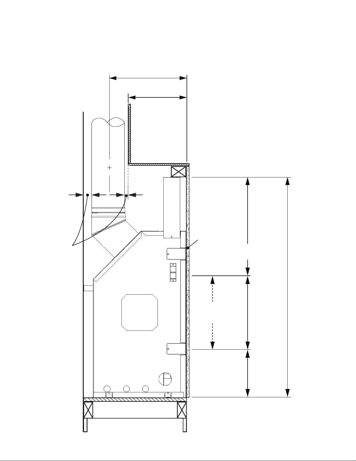
Installation Planning
Venting Considerations—Vertical Takeoff
24” pipe section
Min 1”
[25 mm]
*67-1/2” [ 1715 mm] with 24” vent pipe
Required
clearance
to vertical
37” [940 mm]
stand-o
pipe is
within
space
Fireplace Left Side View
Stand-o
19-1/4”
[489 mm]
14-1/2”
[369 mm]
9-3/8”
[238 mm]
Framing
*Notes—ALL venting considerations
• Dimensions of venting are based on using Dura-Vent elbows. Elbow curve radius
dimensions will vary when using other
brands. In general, other brands have
slightly bigger radius.
• Minimum 24 inches vertical pipe section
required right at unit. Refer to venting chart
on page 30 for allowable horizontal runs.
• 3 inches clearance to combustibles required above horizontal pipe. Slope horizontal pipe upwards 1/4 inch per foot. 1
inch clearance required around sides and
bottom of horizontal pipe and around vertical pipe.
• When calculating eff ective pipe lengths
subtract approximately 1-1/2 inch for pipe
joint - for example, a 12 inches pipe section will add approximately 10-1/2 inches
overall.
43” [ 1093 mm] to underside of combustible cavity
Venting Considerations—Horizontal Takeoff
24” pipe section
*70” [ 1778 mm] with 24” vent pipe
36-1/2” [927 mm]
2-1/2”
[64 mm]
Fireplace Left side view
19-1/4”
[489 mm]
14-1/2”
[369 mm]
9-3/8”
[238 mm]
43” [ 1093 mm] to underside of combustible cavity
15

Installation Planning
Wall Finish
Material Specifi cations
Non-Combustible
Material which will not ignite and burn. Such materials
are those consisting entirely of steel, iron, brick, tile,
concrete, slate, glass or plasters, or any combination
thereof.
Materials that are reported as passing ASTM E 136,
Standard Test Method for Behavior of Materials in a
Vertical Tube Furnace at 750°C shall be considered
non-combustible materials.
Combustible
Materials made of or surfaced with wood, compressed
paper, plant fi bers, plastics, or other material that
can ignite and burn, whether fl ame proofed or not,
or plastered or unplastered shall be considered
combustible materials.
Minimal coverage area of non-combustible cement board.
Any wall ȴQLVKDSSOLHGWRVKDGHGDUHDPXVWEHQRQFRPEXVWLEOH
Min. 60” [1524 mm]
Non-Combustible Cement Board
The L2 Linear fi replace requires a 1/2” (13mm) thick
non-combustible cement board to be used as a wall
surface immediately surrounding the unit’s opening—
see diagram for minimum coverage.
Extending the cement board well beyond the minimum
shown will help avoid cracking due to diff erential
expansion of materials.
Pre-drill cement board with oversized holes and do
not over-tighten screws to avoid cracking due to heat
expansion.
Standard gypsum wall board may be used beyond the
perimeter of the cement board.
NON-COMBUSTIBLE MATERIALS ONLY
MATÉRIAUX INCOMBUSTIBLES SEULEMENT
READ INSTRUCTIONS
CONSULTEZ LE GUIDE D’INSTALLATION
DD
A
B
Min. 44-1/2” [1130 mm]
C
With 1750 or
inches [mm]
1775 trims
Min. 20-1/2 [521] Min. 20-1/8 [511]
A
14-3/4 [375] 15-13/16 [401]
B
Min. 9-1/4 [235] Min. 8-9/16 [218]
C
Min. 5 [127] Min. 4-1/2 [114]
D
Min. 50 [1270] Min. 51-1/16 [1296]
E
E
NON-COMBUSTIBLE MATERIALS ONLY
NON-COMBUSTIBLE MATERIALS ONLY
READ INSTRUCTIONS
MATÉRIAUX INCOMBUSTIBLES SEULEMENT
CONSULTEZ LE GUIDE D’INSTALLATION
READ INSTRUCTIONS
MATÉRIAUX INCOMBUSTIBLES SEULEMENT
CONSULTEZ LE GUIDE D’INSTALLATION
with 1730CIK kit
Non-combustible
cement board
required thickness:
1/2” [13 mm]
Linear 1700 outline
LQFOXGLQJVWDQGRV
Joints preferred at corners
to prevent cracking
Flush with bottom of unit;
add extra cement board
to overlap framing.
16
Installation Planning
1/4”
(235 mm)
Possible screw loc
(in the designated
ard flush with bo
of heater; add extra
overlapping framing
Non-Combustible Finishing Over Cement
Board
Additional non-combustible material such as tile, etc.,
may be applied over top of the cement board or you
may choose to leave it fi nished clean with no tile, etc.
Be aware that a trim is always required. Finish should
not cover the trims.
1775 and 1750 Trims
Only the 1775 and 1750 style trims will accept tile, etc.
tucked behind them (up to 5/8” thick for the 1775 and
up to 1 inch thick for the 1750).
1730 Trim
1730 trim must be installed BEFORE cement board.
Cement board and fi nishes are applied to the perimeter
of the trim frame. Cement board and fi nished CANNOT
be tucked under this trim.
Wall Finish
Wider trim (1750)
can adjust up to 1”
forward of sur face of
cement board.
Cement board tucks
behind trim.
Narrow trim (1775)
can adjust up to 5/8”
forward of sur face of
cement board.
Cement board tucks
behind trim.
Clean Installation
Kit 1730CIK requires
HeatShift. Cement
board fi nishes up to
perimeter of frame.
Must install
BEFORE cement
board.
17

Installation Planning
Wall Finish
Avoiding Cracking Wall Finishes
We recommend installing the optional HeatShift
System to reduce the wall temperatures and minimize
the possibility of cracking wall fi nishes.
WARNING
HeatShift System MUST be installed on
this appliance when using 1730CIK—Clean
Installation Kit.
If a clean fi nish with no tile, etc. is desired, joints in the
cement board and the transition to gypsum board
will require special attention if future cracking is to be
controlled. Be aware that temperatures on the noncombustible wall surface above the appliance can
exceed 200°F (93°C).
Below are some tips on how to best avoid any cracking:
• Allow materials to dry thoroughly before fi nishing the
wall. Cement board has the ability to absorb up to 30
percent of its weight in water and may shrink as much
as 1/8” over a 48” length when drying from a saturated condition. Running the fi replace for an extended
period before fi nal fi nishing will help drive out mois-
ture.
• Always pre-drill screw holes through cement board
and use screws specifi c for material used.
• Always use mesh tape over joints.
• Always stagger joints in wall board.
• Behind joints, double up studs or use studs “on the
fl at” to add extra support to the joint. Adhesive on
the backside of wall board behind any joints can help
control diff erential movement.
• Use multiple, thinner coats of joint compound and allow to dry thoroughly between coats.
• Ensure framing materials are dry.
• After fi nishing the wall, introduce heat gradually to
slowly dry any excess moisture rather than drying too
fast.
• Avoid notching cement board or tiles around corners
of window opening and instead provide a joint that
intersects the corner.
• Avoid using lage one-piece slab of material with a
cut-out in the middle as a surround for the fi replace.
Expansion above the opening will cause cracking at inside corners. Provide a joint that intersects the inside
corner to avoid cracking.
18
Provide joints
either here or
here
Cracks

Venting
Overview
Top or Rear Outlet
This unit is supplied with a top vent outlet which can
be fi eld-converted to a rear vent outlet. See Appliance
Preparation section for more information.
Vent Material
This unit is approved for installation using
4 x 6-5/8 inches co-axial direct vent pipe and
accessories as listed in the Approved Venting Components
section on pages 61–62 of this manual. Follow the
installation instructions supplied with the individual
venting accessories.
This unit may also be converted to co-linear (1 x 3 in by
1 x 4 in) venting for use in solid-fuel burning fi replaces
and chimneys using adapters and accessories—see list
in the Approved Venting Components section on pages
61–62 of this manual.
Vent Sealing
Seal all outer coaxial pipe and elbow joints, including
sectioned elbow joints, using high quality, high temperature 2 inch wide self-adhesive aluminum foil tape
(Nashua-322-2 brand or similar). Wrap the tape completely around all joints and press fi rmly to seal.
A high temperature black silicone sealant may be used
in the outer joints as a substitute to foil tape.
Ensure all the pipe joints have a minimum of 1¼ inch
overlap.
Tape all joints
(including all
elbow joints)
Wall Thickness
The appliance vent is suitable for penetrating a
combustible wall assembly up to 8 inches in thickness.
A non-combustible wall can be of any thickness up to
the maximum horizontal run of vent pipe allowed for
the particular installation.
Framing Vent in Combustible Walls & Ceilings
When penetrating through combustible walls and
ceilings, frame a minimum of 10 in x 10 in opening and
ensure that the insulation is kept clear of the vent pipe
using either a wall thimble or an attic insulation shield.
Follow the installation instructions supplied with the
individual venting components.
Align the vent center
to the center of the
frame
10” (254 mm)
10” (254 mm)
Important Installer Notice – Weather
Sealing & Vapor Barriers
It is the installer’s responsibility to ensure that vent
installations through exterior walls are caulked and
weatherproofed in such a manner as to:
• Prevent rain water from entering the wall from the
weather side by adequately caulking the outer vent
plate to the exterior wall surface.
• Prevent moisture inside the home from penetrating into the wall structure by ensuring the inside
wall plate is adequately sealed to the inside vapor
barrier.
• Prevent rain water and moisture from entering the
walls by sealing the joints between the outer vent
tube and the inner and outer wall plates.
We recommend the use of a high quality
polyurethane sealant.
All horizontal pipe runs must be graded 1/4 inch per
foot upwards in the direction of the exhaust fl ow. The
fi nal pipe length, when terminating through the wall
may be graded downwards slightly to prevent water
migration.
19

HORIZONTAL
TERMINATION
2-PIECE
WALL THIMBLE
PIPE LENGTH
HORIZONTAL
TERMINATION
2-PIECE
WALL THIMBLE
PIPE
LENGTH
PIPE
LENGTH
PIPE
LENGTH
PIPE
LENGTH
90˚ ELBOW
CEILING
FIRESTOP
ATTIC
FIRESTOP
ATTIC
INSULATION
SHIELD
FLASHING
STORM
COLLAR
VERTICAL
TERMINATION
PIPE
LENGTH
90˚ ELBOW
90˚ ELBOW
Venting
Typical Co-axial Venting Components
Co-Axial
Rear Outlet
20
Top Out l et Top Out l et
Venting
Co-Axial
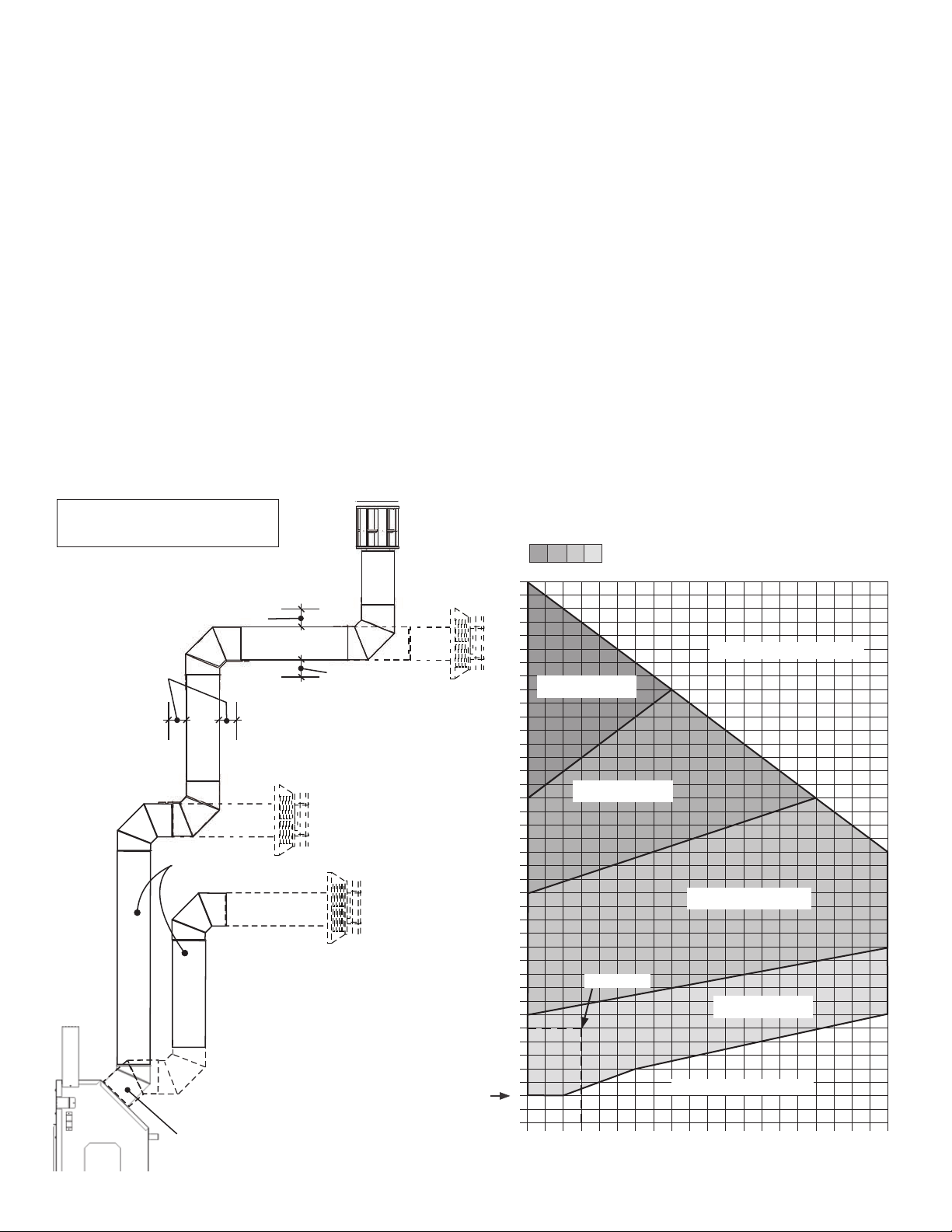
How to Read the Venting Chart
The chart below applies to co-axial roof or wall
termination.
1. A minimum vertical rise of 24 inches is required
directly off the unit or after fi rst elbow, as shown.
2. The total length of the vent pipe cannot exceed
40 feet.
3. The minimum vertical height with roof termination
is 6 feet.
4. Any combination of rise and run can be used as
long as they are within the allowable limits shown
on the chart below.
5. A maximum of 4 x 90 degrees elbows—or
equivalent (2 x 45 degrees = 90 degrees)—can
Venting Chart
4 x 90º ELBOWS MA XIMUM
(or equivalent)
V3
1” min. around
bottom & sides
of horizontal pipe
1” min.
all around
vertical pipe
3” min.
above top of
horizontal pipe
H1
V2
be used. Excludes the 45 degrees take-off elbow
shipped with the appliance.
6. Each 90 degrees elbow installed on the horizontal
plane is equivalent to a 3 feet horizontal pipe;
therefore, 3 feet must be subtracted from allowable
horizontal run. (45 degrees elbow is equivalent to
18 inches horizontal pipe.)
7. All horizontal pipe runs must be graded 1/4 inch per
foot upwards in the direction of the exhaust fl ow.
The fi nal pipe length, when terminating through the
wall may be graded downwards slightly to prevent
water migration.
8. A restrictor adjustment is required for most
installations having a vertical rise—see “Restrictor
Settings” on page 22.
Note: The restrictor is shipped installed at the
exhaust exit of the fi rebox.
Allowable Co-Axial
Vent Confi gurations with
restrictor positions
40
38
36
34
32
Position #5
30
28
NO INSTALLATION
V1
Minimum 24”
pipe section
Example 1
V Value = V1 (2 ’) + V2 (4’ ) + V3 (1’)= 7’
H Value = H1 (2’) = 2 ’
Restrictor position # 1 required
45° elbow take-o
supplied with unit
24” minimum
vertical pipe rise
off unit or after
fi rst elbow
26
24
22
20
18
16
14
VERTICAL RISE (ft)
12
10
8
6
4
2
0
02468101214161820
Position #4
Positions #2/3
Example 1
Position #1
NO INSTALLATION
HORIZONTAL RUN (ft)
21

Venting
Restrictor Settings
The restrictor is located in the roof of the fi rebox
hidden above the top liner panel. Adjust the restrictor
before installation of the top liner panel. Should
subsequent adjustment be required, you will need to
remove the top liner panel—see “Liners” on page 38.
ALL INSTALLATIONS REQUIRE A RESTRICTOR for
improved fl ame picture and performance. This unit is
supplied with a pre-fi tted restrictor having fi ve diff erent
positions or settings. The restrictor is shipped mounted
at the maximum open position which is used for rear
venting with no vertical rise. The level of restriction
required depends on the vertical rise in the venting
system and, to a lesser degree, the horizontal run and
number of elbows.
The amount of restriction is based on laboratory tests.
The ideal restrictor position may vary slightly, especially
when the vent pipe length is near the limits of the
acceptable confi gurations for each type of restrictor.
Co-Axial
Inside fi rebox—roof venting port
The chart on the previous page shows
the vent restrictor required relative to the
length of the vent pipe.
To set the restrictor position:
1. Establish the required position of the
restrictor looking up the venting table
on the previous page.
2. Release the screws (2) on each side of
the restrictor already installed on the
fi rebox roof port.
3. Slide the restrictor in the required position.
4. Tighten the screws.
Position #1 Position #2
Position #3 Position #4
22
Position #5

V
G
A
Min. 72”
Max. 72”
Venting
Co-Axial
Horizontal Vent Termination
Horizontal Vent Termination Location
• The vent terminal must be located on an outside
wall or through the roof.
• This direct vent appliance is designed to operate
when an undisturbed airȵ ow hits the outside vent
terminal from any direction.
• The minimum clearances from this terminal that
must be maintained when located on an outside
wall are shown in ȴ gure below. Any reduction in
these clearances could result in a disruption of the
airȵ ow or a safety hazard. Local codes or regulations
may require greater clearances.
• The vent terminal must not be recessed into a wall
or siding.
• The vent terminal should be positioned where any
snowdrifts will not cover it.
• Sidewall vent terminations require a terminal guard
such as 658TG or 845TG when accessible—within 7’
of ground.
Alcove detail
(open on one
side) Normal
ceiling/soɝ t
clearances
apply.
KEY VENT TERMINAL LOCATIONS - MINIMUM DISTANCES
Inches Cm
A Clearance above grade, verandah, porch, deck or balcony 12 30
B Clearance to window or door that may be opened 12 30
C Clearance to permanently closed window (recommended to prevent condensation on window) 12 30
Vertical clearance to ventilated soɝ t located above the terminal within a horizontal distance of 2 feet (60 cm)
D
from the center-line of the terminal
E Clearance to unventilated soɝ t 12 30
F Clearance to outside corner 12 30
G Clearance to inside corner 12 30
Horizontal clearance to center-line of meter/regulator assembly located within 15 feet (4.6bm) below the
H
terminal
Clearance to service regulator vent outlet
I
J Clearance to non-mechanical air supply inlet to the building or the combustion air inlet to any other appliance 12 30
K Clearance to a mechanical air supply inlet 72 180
Clearance above paved sidewalk or a paved driveway located on public property
Note: A vent must not terminate directly above a sidewalk or paved driveway, which is located bet ween t wo single-
L
family dwellings and serves both dwellings. THIS DOES NOT APPLY to direct vent, non-consdensing appliances in
the Province of Ontario.
Clearance under a verandah, porch, deck or balcony
M
Only permitted if veranda, porch, deck or balcony is fully open on a minimum of 2 sides beneath the ȵ oor
Note: Local codes and regulations may require di erent clearances.
MINIMUM
CLEARANCE
18 4 6
36 90
36 90
84 210
12 30
23

Venting
Vertical Vent Termination
Co-Axial
Roof Pitch
Flat to 7/12 1'
Over 7/12 to
8/12
Over 8/12 to
9/12
Over 9/12 to
10/12
Over 10/12 to
11/ 12
Over 11/12 to
12/12
Over 12/12 to
14/12
Minimum
"H" (feet)
1.5'
2.5’
3.25’
Overhang should not
extend beyond vent if
Horizontal
overhang
2’
Vertical
wall
4’
5’
Roof
ashing
Termination
cap
Min.
18”
Storm
collar
within 48” of
termination cap
Min. 24”
(unvented sot)
Min. 36”
(vented sot)
‘H’
24
Venting
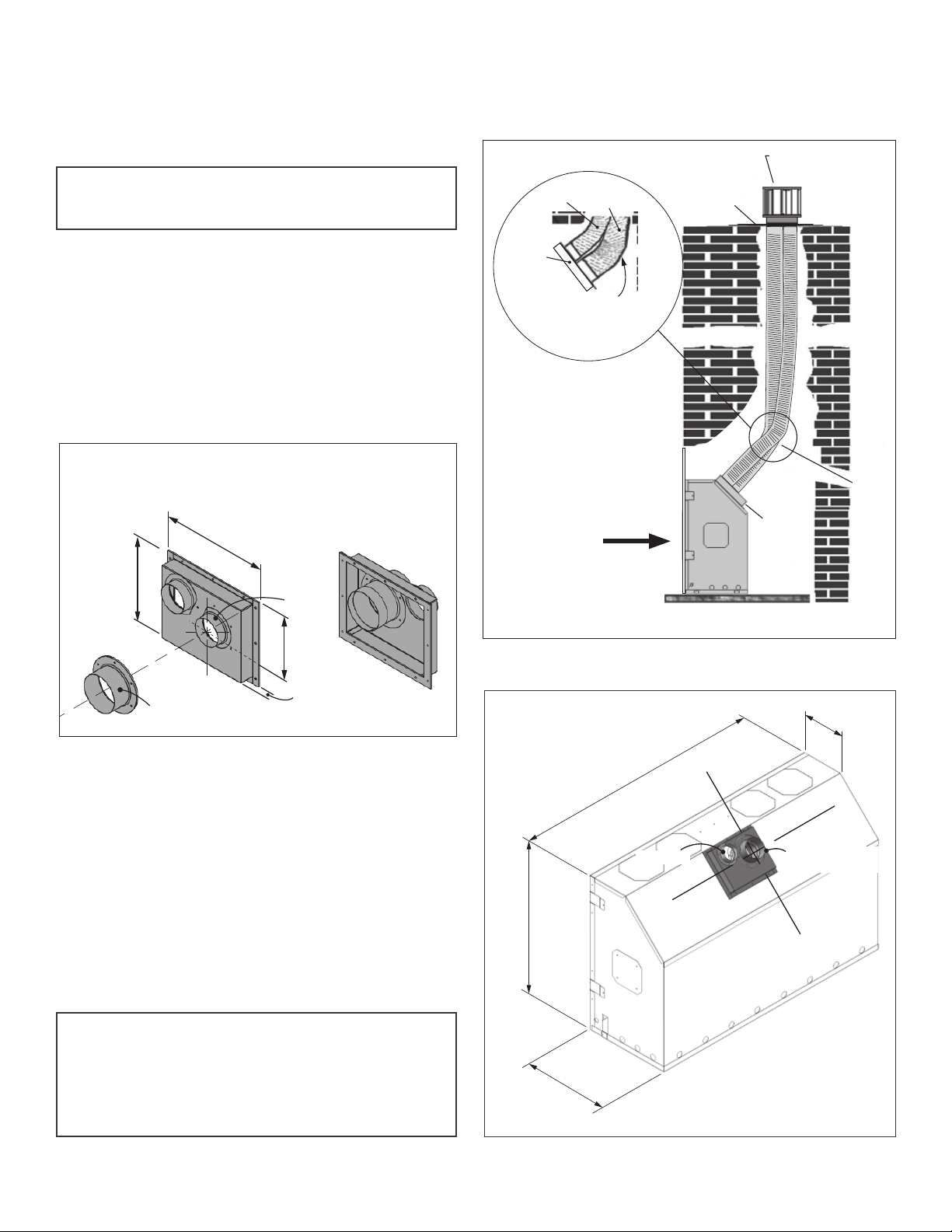
Co-Linear Conversion
Installation into existing fi replace cavity
Note: Co-linear portion of vent system may only be
installed within a solid-fuel burning fi replace and
chimney.
The appliance must not be connected to a chimney fl ue
serving a separate solid-fuel burning appliance.
Requires the Valor Co-Axial to Co-Linear appliance
Adapter 1156CLA, two lengths of 2-ply fl exible chimney
liner both approved for venting gas appliances: one 3”
diameter liner for intake and one 4” diameter liner for
exhaust, a 3 x 4 co-linear termination kit and fl ashing.
Firebox zero clearance standoff s supplied with the heater
may be removed to suit this application.
1156CLA Co-Linear Vent Adapter
FRONT REAR
11-11/16”
9-3/8”
3” exhaust
collar
3” intake
liner
Co-linear
adapter
3” min. bend radius
for intake liner and
4” min. bend radius
for exhaust liner
Any fi nishes
applied
around the
fi replace
must be non-
combustible
4” exhaust
liner
Flashing
Engine
Approved 3 x 4 co-linear
termination
1156
Co-linear
adapter
1 x 3”
intake
liner
and
1 x 4”
exhaust
liner
4”
4” exhaust
collar adapter
1-1/2”
Rules for Co-Linear Venting
• Maximum 40 feet vertical pipe
• Minimum 10 feet vertical
• Maximum off set 8 feet with liners at minimum
45 degrees from horizontal plane
• Restrictor: Not required when using co-linear venting.
Installation
For installation of the adapter to the appliance, see the
instructions supplied with the 1156CLA.
Note: Co-linear fl exible aluminum venting should be
professionally inspected periodically for corrosion
and damage and replaced when necessary. If the
installation does not allow for future inspection or
replacement of the fl exible aluminum venting, then
stainless steel vent liners should be used.
Co-Linear installation into existing fi replace
Dimensions with 1156CLA Co-Linear Adapter
52”
3” intake
32-3/8”
18-1/8”
8-5/8”
4” exhaust collar
on the centerline
25
Venting
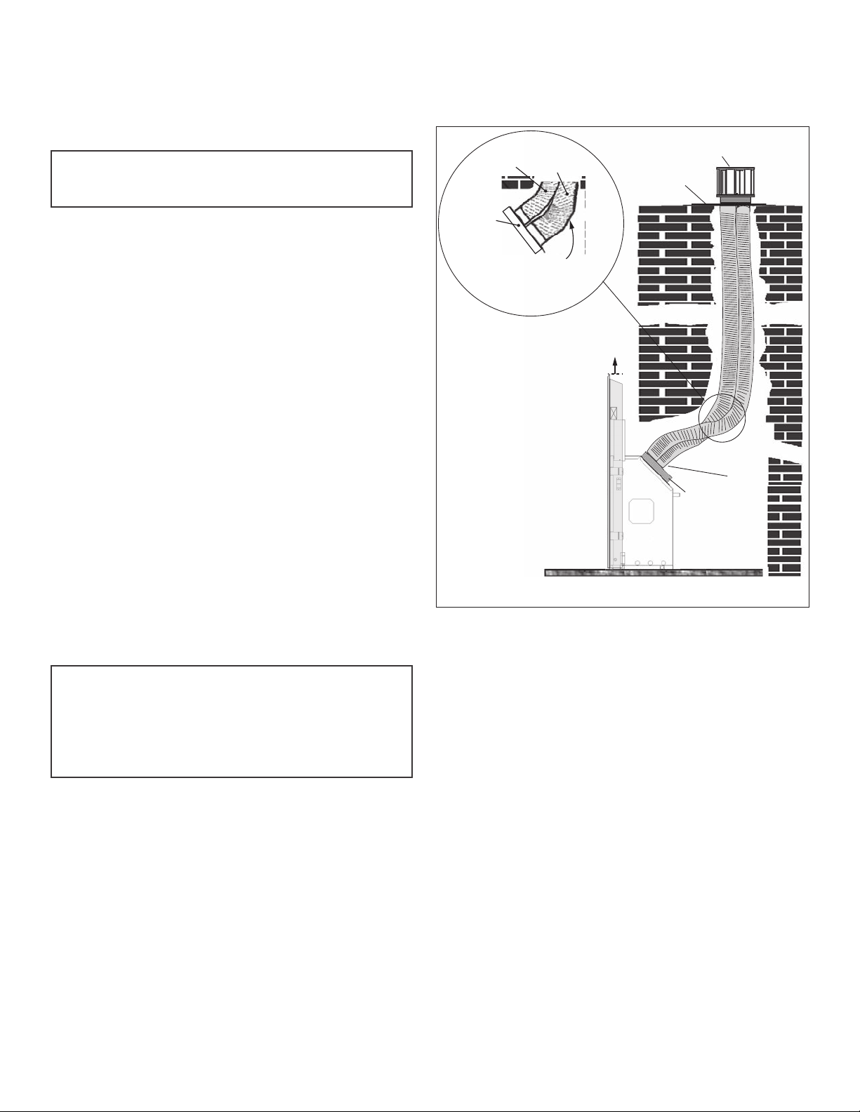
Co-Linear Conversion
Installation partially into fi replace cavity
Note: Co-linear portion of vent system may only be
installed within a solid-fuel burning fi replace and
chimney.
The appliance can be adapted to co-linear applications
using an existing chimney. The appliance must not be
connected to a chimney fl ue serving a separate solid-
fuel burning appliance.
Requires the Valor Co-Axial to Co-Linear appliance
Adapter 1156CLA, 46DVA-GLC34 or equivalent, two
lengths of 2-ply fl exible chimney liner both approved
for venting gas appliances: one 3” diameter liner for
intake and one 4” diameter liner for exhaust, a 3 x 4 colinear termination kit and fl ashing.
The appliance must be fully enclosed while maintaining
clearances to combustibles detailed elsewhere in this
manual.
Rules for Co-Linear Venting
• Maximum 40 feet vertical pipe
• Minimum 10 feet vertical
• Maximum off set 8 feet with liners at minimum
45 degrees from horizontal plane
• Restrictor: Not required when using co-linear venting.
Approved 3 x 4
3” intake
liner
Co-linear
adapter
3” min. bend radius
for intake liner and
4” min. bend radius
for exhaust liner
Co-Linear installation partially into existing fi replace
4” exhaust
liner
Clearances
to combustible
materials listed
elsewhere in this
manual apply
Framed
wall
co-linear termination
Flashing
1156
Co-linear
adapter
Engine
1 x 3”
intake
liner
and
1 x 4”
exhaust
liner
Note: Co-linear fl exible aluminum venting should be
professionally inspected periodically for corrosion
and damage and replaced when necessary. If the
installation does not allow for future inspection or
replacement of the fl exible aluminum venting, then
stainless steel vent liners should be used.
26

Venting
Co-Linear Conversion
Installation into existing adjacent chimney
Note: Co-linear portion of vent system may only be
installed within a solid-fuel burning fi replace and
chimney.
The appliance can be adapted to co-linear applications
using an existing chimney. The appliance must not be
connected to a chimney fl ue serving a separate solid-
fuel burning appliance.
Requires the Co-Axial to Co-Linear appliance Adapter
46DVA-34CLAA or equivalent, two lengths of 2-ply
fl exible chimney liner both approved for venting gas
appliances: one 3” diameter liner for intake and one 4”
diameter liner for exhaust, a 3 x 4 co-linear termination
kit and fl ashing.
The appliance must be fully enclosed while maintaining
clearances to combustibles detailed elsewhere in this
manual.
Approved 3 x 4
co-linear termination
4” exhaust
liner
3” intake
liner
Flashing
Rules for Co-Linear Venting
• Maximum 40 feet vertical pipe
• Minimum 10 feet vertical
• Maximum off set 8 feet with liners at minimum
45 degrees from horizontal plane
• Restrictor: Not required when using co-linear venting.
Note: Co-linear fl exible aluminum venting should be
professionally inspected periodically for corrosion
and damage and replaced when necessary. If the
installation does not allow for future inspection or
replacement of the fl exible aluminum venting, then
stainless steel vent liners should be used.
Approved 3 x 4
4” exhaust
liner
3” intake
liner
co-linear termination
Flashing
3” min. bend radius
for intake liner and
3” min. bend radius
for intake liner and
4” min. bend radius
for exhaust liner
46DVA-34CLAA
or 46DVA-GCL34
Engine
Co-linear
adapter
1 x 3”
intake
liner
and
1 x 4”
exhaust
liner
Clearances
to combustible
materials listed
elsewhere in this
manual apply
Installation using 46DVA-34CLA A Installation using 46DVA-GCL34
Framed
wall
4” min. bend radius
for exhaust liner
Clearances
to combustible
materials listed
elsewhere in this
manual apply
46DVA-GCL34
or 46DVA-34CLAA
Co-linear
Framed
wall
adapter
Max. 12”
1 x 3” intake liner
and
1 x 4” exhaust liner
Engine
27
Venting
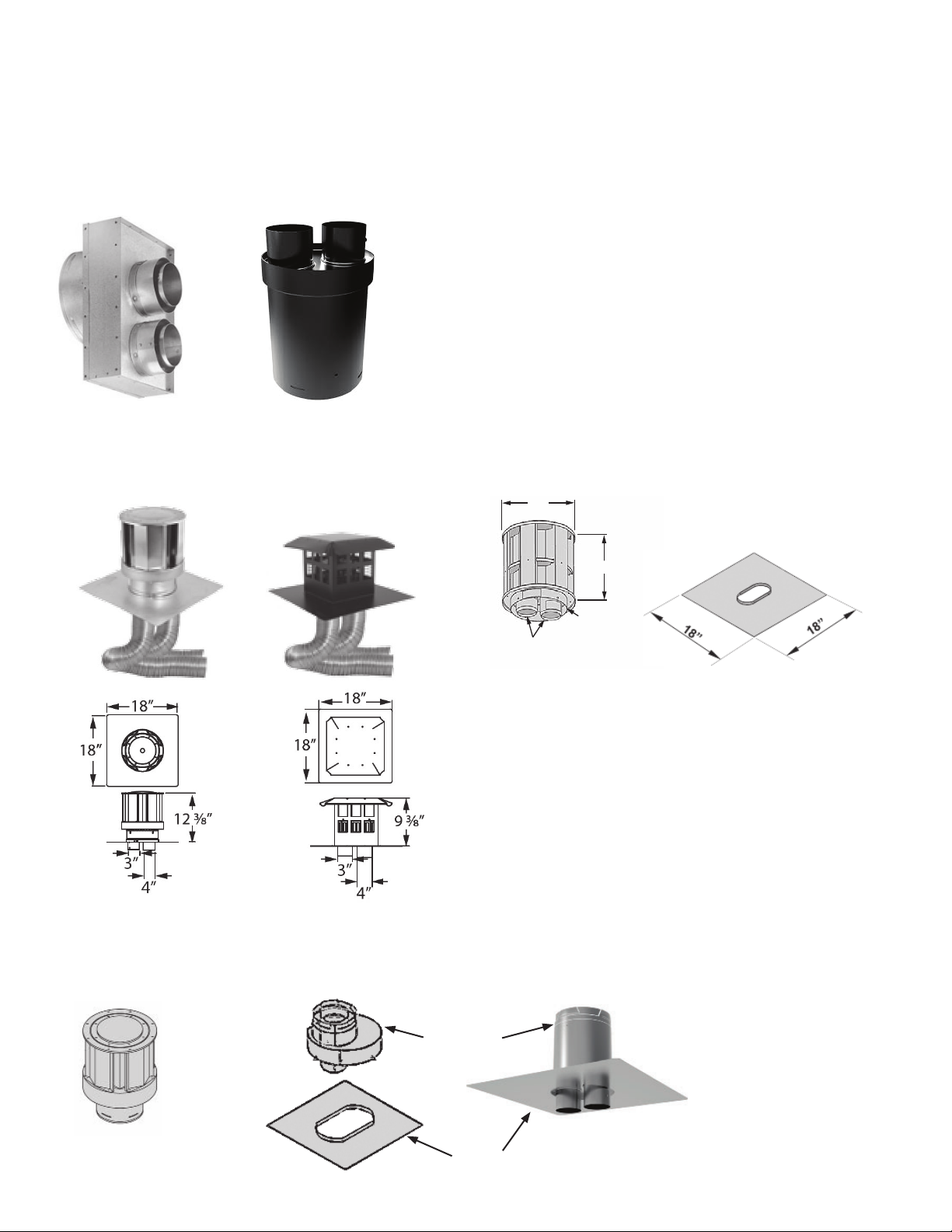
Example of co-linear conversion accessories
Examples of Co-axial to Co-linear Appliance Adapters
Co-Linear Conversion
46DVA-GCL34
46DVA-34CLAA
Examples of Co-linear Terminal Configurations
10”
10”
7-5/8” dia.
collar
3” Inlet & Exhaust
A 3” - 4”
.
Collars
adapter may be used
for exhaust liner.
Flashing KitCo-Linear Terminal (typical)
Co-linear Termination Kits
Alternate Co-linear to Co-axial Conversion at Terminal
Co-Linear to CoAxial Adapter
With...
Co-axial Terminal Cap
Flashing
28

Installation
Unpack Appliance
Beware of sharp edges! Wear gloves!
1. Remove the cardboard wrapping and the wood pallet from the appliance and discard.
2. Unpack any loose items from around the appliance.
3. Remove the window and set aside in a safe place
to avoid damage—see”Remove Window” on page
32.
4. Verify that you have all the components required for the installation, including:
• approved cement board;
• liners and fuel bed (in separate cartons);
• trim kit with barrier screen;
• venting components and accessories;
• optional HeatShift system if used;
• electrical components if installing optional
decorative light wall switch or blower.
Appliance Preparation
Standoff
Standoff s installed
Fit Standoff s
The standoff s are supplied fl at on the fi rebox sides
and fi xed at one end. Swivel up the fl at standoff s, bend
them as shown and fi x the loose end to the top of the
fi rebox.
Remove Heat Shield
Remove the heat shield from the top of the appliance
case (3 screws). If using a rear outlet, keep the shield
to reinstall after converting the top to rear outlet—see
next subsection. If using the top outlet or the HeatShift
system, discard the shield.
Fold fl at
standoff s
Remove heat shield (3 screws)
29

Installation
Convert from Top to Rear Outlet (if required)
This unit is supplied with a top vent outlet which can
be fi eld-converted to a rear vent outlet.
Please note that the rear outlet requires the installation of the heat shield on top of the heater case as
indicated.
1. Remove the top outlet collar (6 screws).
2. Swivel the collar and install as a rear outlet (6 screws).
3. Reinstall the heat shield to the top of the appliance
case (3 screws).
Appliance Preparation
Remove top outlet (6 screws)
Reinstall heat shield
to top of appliance
(3 screws)
Swivel the outlet so that it
is oriented towards the rear
and reinstall to heater
(6 screws)
30
Rear outlet with required heat shield
 Loading...