

HORIZON
645CFV Clearview
Vintage Iron Front Kit
CSA approved for use with Valor Models 534I Heaters ONLY
Installation Instructions
INSTALLER
!
A barrier designed to reduce the risk of burns from the hot viewing
glass is provided with this appliance and shall be installed
for the protection of children and other at-risk individuals.
The 645CFV Horizon Clearview Vintage Iron Front is designed to be used on
the 534I Valor heaters.
Mantel clearances are unchanged from those shown in the 534I installation
manual.
WARNING
HOT GLASS WILL
CAUSE BURNS.
DO NOT TOUCH GLASS
UNTIL COOLED.
NEVER ALLOW CHILDREN
TO TOUCH GLASS.
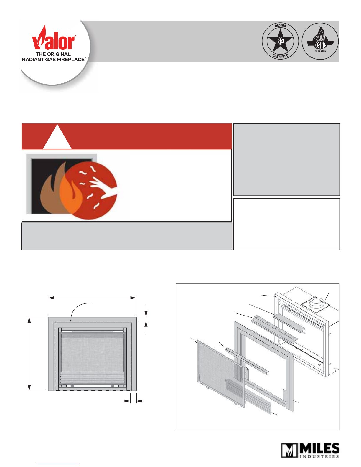
37-1/4” (946 mm)
Appliance
outline
1-1/2”
(38 mm)
Note: Wall fi nish must be fl ush or slightly
in front of this frame on heater!
Heat Exchanger Cover
Heat Baffl e
Leave this manual
with the appliance.
CONSUMER
Retain this manual
for future reference.
Note: This kit must be installed
by a qualifi ed installer, service
agency or gas supplier. These
instructions are to be used in
conjunction with the fi replace
main installation instructions.
534I
31-1/4” (794 mm)
*NOTE: Bottom of plate is flush with
bottom of heater. Install bottom of
heater flush with finished hearth.
4002225-05
© Copyright Miles Industries Ltd., 2013
2-1/2”
(64 mm)
Barrier
Screen
Overview (Heater and fret sold separately)
Window
Bolts
Cover
Clearview Front
Fret
Installation
Install the heater as per installation instructions
supplied with it.
Finish the wall at sides up to the black frame on heater.
Finish the wall 1 inch (25 mm) above the top of the
black frame on heater. Ensure that the wall fi nish is
fl ush or slightly in front of the black frame. Allow for
height of fi nished hearth or the backing plate will not
install.
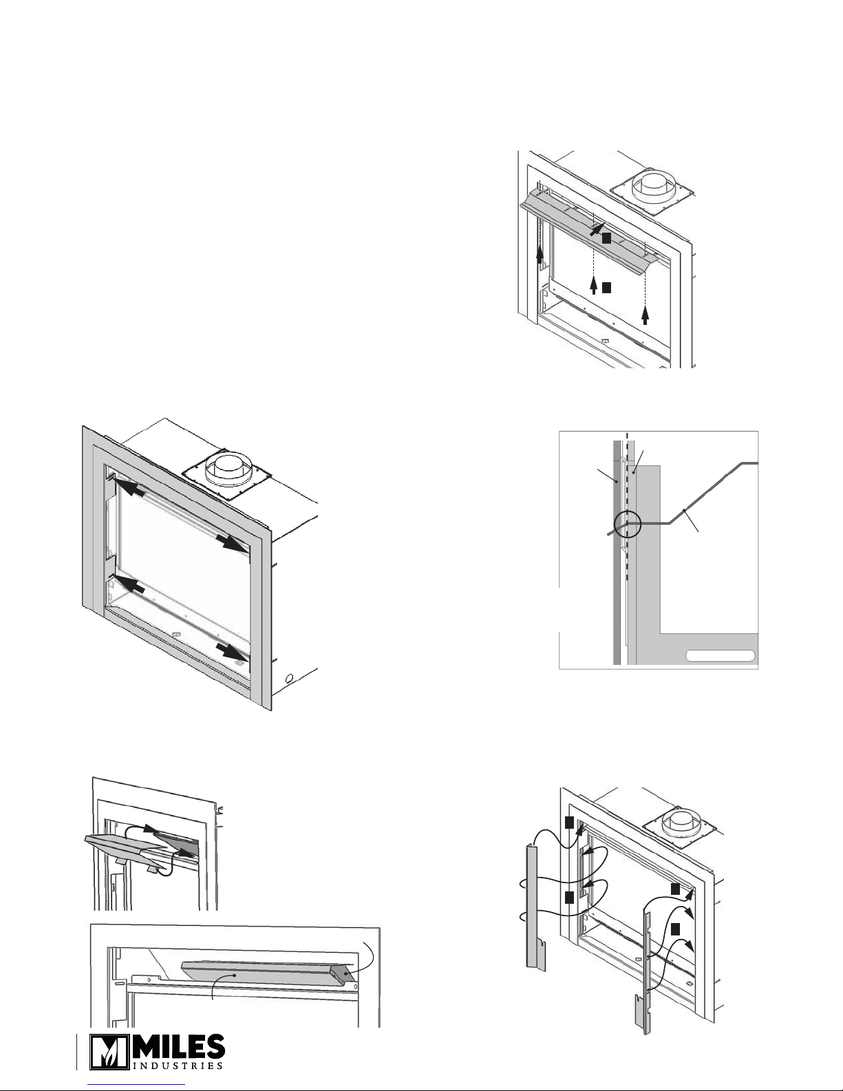
3. Remove the existing baffl e supplied on the heater
(3 screws). Fix the convection heat baffl e supplied
to the heater (3 screws). You may need to remove
the window to gain space for a screwdriver.
Check the appliance manual for window removal
instructions.
If the wall above the heater is fi nished to the black
frame, the wall fi nish must be cut 1 inch (25 mm) to
allow the fi tting of the backing plate.
Alternatively, if the wall fi nish is non-combustible, the
fl ange on the top rear of the backing plate can be
broken off the plate to allow the fi nish behind the plate.
1. Install the backing plate to the heater fi xing it with
4 screws provided. The position of the plate can
be adjusted front to back to accommodate the wall
fi nish thickness.
1
2
Slide the baffl e in or out so that its fi rst bend lines
up with the front face of the backing plate.
Backing Plate3-Sided
Frame
Heat Baffl e
Convection heat baffl e
position—
right side section view
2. Slide in and place the heat exchanger cover as
indicated. The bottom tabs cover the ports.
Heat Exchanger
Heat Exchanger Cover
2
4. Re-install the window if you have removed it. Follow
the procedure supplied in the appliance manual.
5. Fit the side shrouds to the heater by fi rst sliding
them up beside the convection baffl e and then
hooking the tabs down to the heater frame.
1
2
1
2

6. Hook the chosen fret (sold separately).
Four frets are offered for the Clearview Horizon
front: Clearview 646CCB, Traditional RA24TB,
Contemporary RA24CV, or Ventana 1225VFB.
Note: The Ventana Fret 1225VFB must be fi tted
with the valve shield provided in the Clearview
Horizon kit before being installed on the front.
Remove the 2 screws at the back of the fret, fi t the
shield to the back of the fret, and fi x it with the 2
screws.
Clearview Fret
8. Install the barrier screen.
a. Slide the right-hand side tabs between the
3-sided frame front plate and the black backing
plate, resting the bottom tabs on the bottom of
the appliance’s black frame.
b. Holding the screen, slide the left-hand top lever
so that its tab goes behind the front plate.
c. Swivel the left-hand side lever so that its tab
goes behind the front plate.
d. Insure that the screen is secure in all corners.
Ventana Fret
7. Hook the window bolt cover to the top of the
window frame as indicated. Do not hook it to the
fi rebox frame.
Window frame
Window
bolts
cover
Firebox frame
3
 Loading...