

Valor Horizon 615CVI Cast Surround Installation Manual
INSTALLATION MANUAL
Horizon
615CVI Cast Surround
for 534 Heaters fi tted with 610FVI or 611FVI FenderFire Doors
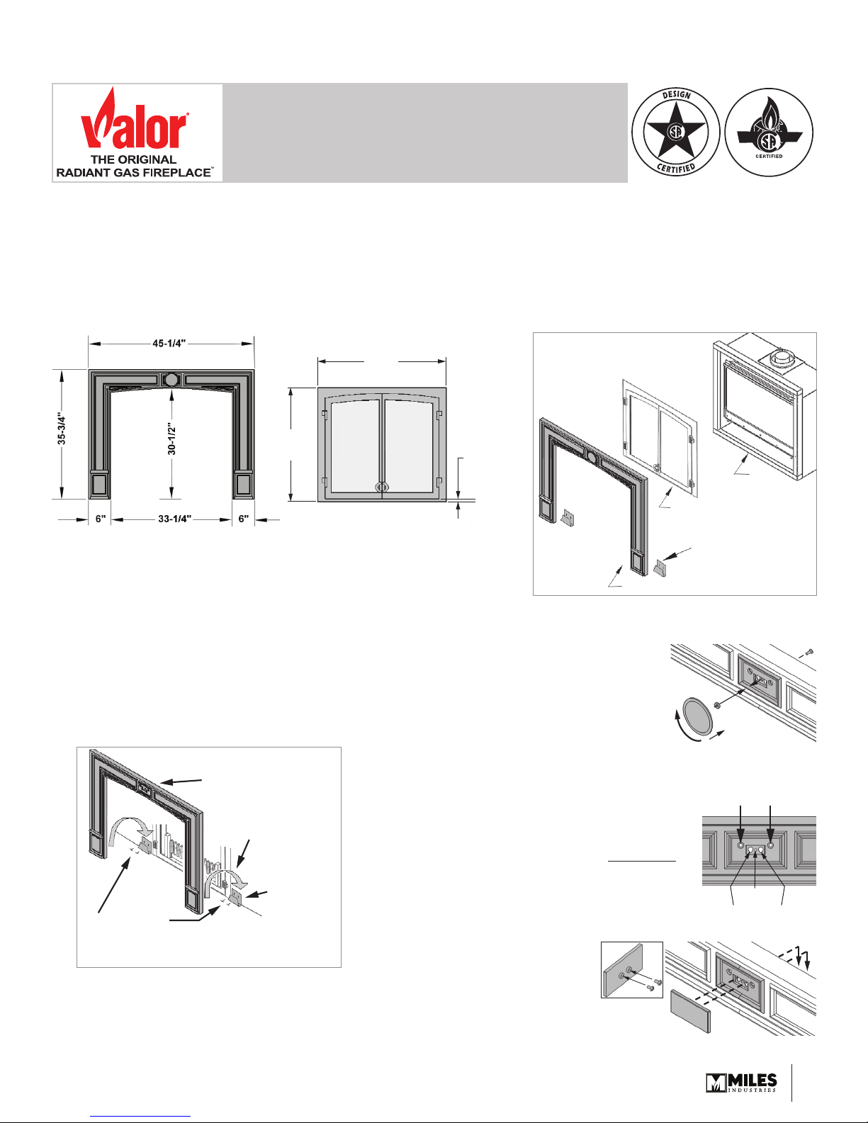
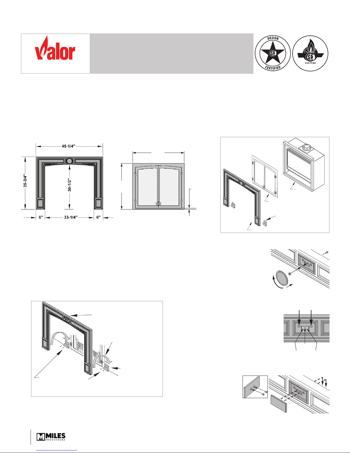
The 615CVI Cast Surround is intended to be used on Valor heaters models 534 fi tted with FenderFire Double Doors
or FenderFire Single Door. Installation of the 615CVI does not aff ect clearances, framing dimensions, or other
specifi cations listed in the heater installation manual. Note: Backing or wall anchors may be required behind wall
fi nish at fi xing points to secure cast surround to wall.
35-3/4”
31-3/4”
*NOTE: Bottom of plate is flush with
bottom of heater. Install bottom of
heater flush with finished hearth.
615CVI Cast Surround Door Kits (sold separately)
Installation
1. Install heater as per installation instructions. Allow for
height of fi nished hearth.
2. Install the door kit or backing plate following instructions
packed with each kit.
3. Fix 2 mounting cleats (supplied) to the wall, fl ush with top of
fi nished hearth and adjacent to the backing plate.
Fasten top of surround
to wall (see step 6)
Backing or wall anchors
(not supplied)
may be required
Drop cast
surround legs
over cleats
Backing or wall
anchors may be
Screw cleats to wall
directly adjacent to backing plate
and flush with top of hearth
Cast Surround Installation
4. The surround comes with a choice of 2 decorative caps
to be fi tted at the center of its top section. Decide which
decorative cap will be fi tted at this point in the
installation.
required
(not supplied)
3/4” Max.
Clearance
bot. of door to
bot. of plate
Overview
If the round cap is chosen by
the customer for this installation,
insert the threaded stud provided
from the back of the surround
through the center hole. Fit the
nut provided on the stud. Do
not screw the cap just yet. If the
rectangular cap is chosen for
this installation, see step 8 below.
615CVI Cast Iron Surround
5. Align and slide surround legs onto
cleats and push the surround fl at
against the wall—see Cast Surround
Installation diagram.
6. Fasten top of surround to wall with
fi xing screws using the 2 outermost
holes from the center fi xing plate.
7. If using the round cap, fi t it to the
surround by screwing it to the stud
previously assembled.
8. If using the
rectangular cap,
fasten the 2 screws
provided to the back
of the cap. Hook the
cap to the key holes
in the surround’s
center fi xing plate.
Adjust screws
length to tighten
or loosen cap
fi tting
Heater
Door Kit
Wall Mounting Cleats (2)
Wall Fixing Points
Round Cap
Fixing Point
Rectangular Cap Fixing Points
4000464-07
©2018, Miles Industries Ltd.
1
r
DIRECTIVES D’INSTALLATION
®
LE PREMIER
FOYER À GAZ RADIANT
MC
Horizon
Bordure de fonte 615CVI
pour les foyers Valor 534 installés avec les portes FenderFire 610FVI ou 611FVI
La bordure de fonte 615CVI est conçue pour être installée avec les foyers Valor 534 munis de la Porte double ou
la Porte simple FenderFire. L’installation de la bordure de fonte 615CVI n’est pas aff ectée par les dégagements,
dimensions d’encadrement ou autres particularités indiquées dans le guide d’installation du foyer.
Note : Des chevilles d’ancrage murales peuvent être nécessaires pour soutenir l’arche de fonte à ses points
de fi xation au mur.
35-3/4”
31-3/4”
*NOTE : Le bas de la plaque est égale au
bas du foyer. Installez le bas du foyer
égal au plancher protecteur fini.
Bordure de fonte 615CVI Portes (vendues séparément)
Dégagement
max. de 3/4”
du bas de la
porte au bas
de la plaque
Concept
Portes
Attaches murales (2)
Bordure de fonte
Foyer
Installation
1. Installez le foyer selon son guide d’installation. N’oubliez
pas de laissez assez d’espace en hauteur pour le plancher
protecteur devant le foyer.
2. Installez les portes ou la plaque de soutien selon les
directives fournies avec ces kits.
3. Fixez les 2 attaches de base au mur immédiatement de
chaque côté de la plaque de soutien, égales au dessus du
plancher protecteur tel qu’indiqué au schéma d’installation.
Fixez le haut de la bordure au mur
(voir étape 6); des chevilles murales
(non fournies) peuvent être requises
Glissez les pattes sur
leur attache de base
Chevilles murales
peuvent être requises
Fixez les attaches au mur
de chaque côté de la plaque de soutien des portes,
alignées avec le dessus de la base de foyer
Installation de la bordure
4. L’emballage de la bordure contient 2 boutons décoratifs
à installer au centre de la section du haut. Décidez
maintenant quel bouton sera installé.
(non fournies)
Pour installer le bouton rond,
insérez la cheville fi letée dans
le trou central de la plaque de
fi xation à partir de l’arrière de
la bordure. Fixez la cheville
avec l’écrou fourni. Ne pas fi xer
le bouton rond maintenant.
Pour installer le bouton
rectangulaire, voir l’étape 8 ci-dessous.
5. Alignez les pattes de la bordure
aux attaches de base et glissez la
bordure sur ces attaches; poussez la
bordure contre le mur tel qu’indiqué
au schéma d’installation.
6. Fixer la bordure au mur à l’aide de
2 vis utilisant les points de fi xation
les plus à l’extérieur du centre de la
section du haut.
Fixation du bouton rectangulai
7. Si vous utilisez le bouton rond,
vissez-le à la cheville fi letée installée précédemment.
8. Si vous utilisez
le bouton
rectangulaire, fi xez
les vis fournies à
l’endos du bouton
et accrochez-le à
la bordure dans les
trous de serrures au
centre de la section
du haut.
Ajustez la
longueur des
vis pour régler
la position du
bouton
Fixation au mur
Fixation du
bouton rond
2
 Loading...