

Valor Horizon 534ILN, Horizon 534ILP Installation And Operation Instructions Manual
HORIZON
Model 534ILN (Natural Gas)
Model 534ILP (Propane)
Direct Vent Gas Fireplace Heater
Installation & Operating Instructions
HOT GLASS WILL
CAUSE BURNS.
DO NOT TOUCH GLASS
UNTIL COOLED.
INSTALLER: Leave this manual
with the appliance.
CONSUMER: Retain this manual
for future reference.
NEVER ALLOW CHILDREN
TO TOUCH GLASS.
WARNING: If the information in these
instructions is not followed exactly, a fi re
or explosion may result causing property
damage, personal injury or loss of life.
Do not store or use gasoline or other
fl ammable vapors and liquids in the vicinity
of this or any other appliance.
WHAT TO DO IF YOU SMELL GAS
• Do not try to light the appliance.
• Do not touch any electrical switch; do not
use any phone in your building.
• Immediately call your gas supplier from
a neighbor’s phone. Follow the gas
supplier’s instructions.
• If you cannot reach your gas supplier, call
the fi re department.
Installation and service must be performed
by a qualifi ed installer, service agency or the
gas supplier.
Please read this manual
BEFORE installing and
operating this appliance.
This appliance may be installed in an
after-market permanently located,
manufactured (mobile) home where not
prohibited by local codes.
This appliance is only for use with the type
of gas indicated on the rating plate. This
appliance is not convertible for use with
other gases, unless a certifi ed kit is used.
This appliance is a domestic room-heating
appliance. It must not be used for any other
purposes such as drying clothes, etc.
This appliance is suitable for installation in a
bedroom or bed sitting room.
Massachusetts: The piping and fi nal
gas connection must be performed by a
licensed plumber or gas fi tter in the State of
Massachusetts. Also, see Carbon Monoxide
Detector requirements under “Safety and
Warning Information” on page 5.
MILES INDUSTRIES LTD., British Columbia, Canada
4001950-13
© 2011, Miles Industries Ltd. All rights reserved.
Manufactured by
www.valorfi replaces.com
Thank You ...
For purchasing a Valor by Miles Industries. Your new radiant gas heater is a technical
appliance that must be installed by a qualifi ed dealer. Each Valor fi replace is fully
tested during the production process for your safety and comfort.
Your unit has been professionally installed by:
Dealer Name _______________________________________
Phone Number ______________________________________
Should you encounter an operational problem, call your dealer immediately.
Do not try to repair the unit as you may cause an injury or damage the fi replace.
The information contained in this installation manual is believed to be correct at
the time of printing. Miles Industries Ltd. reserves the right to change or modify any
information or specifi cations without notice. Miles Industries Ltd. grants no warranty,
implied or stated, for the installation or maintenance of your heater, and assumes no
responsibility for any consequential damage(s).
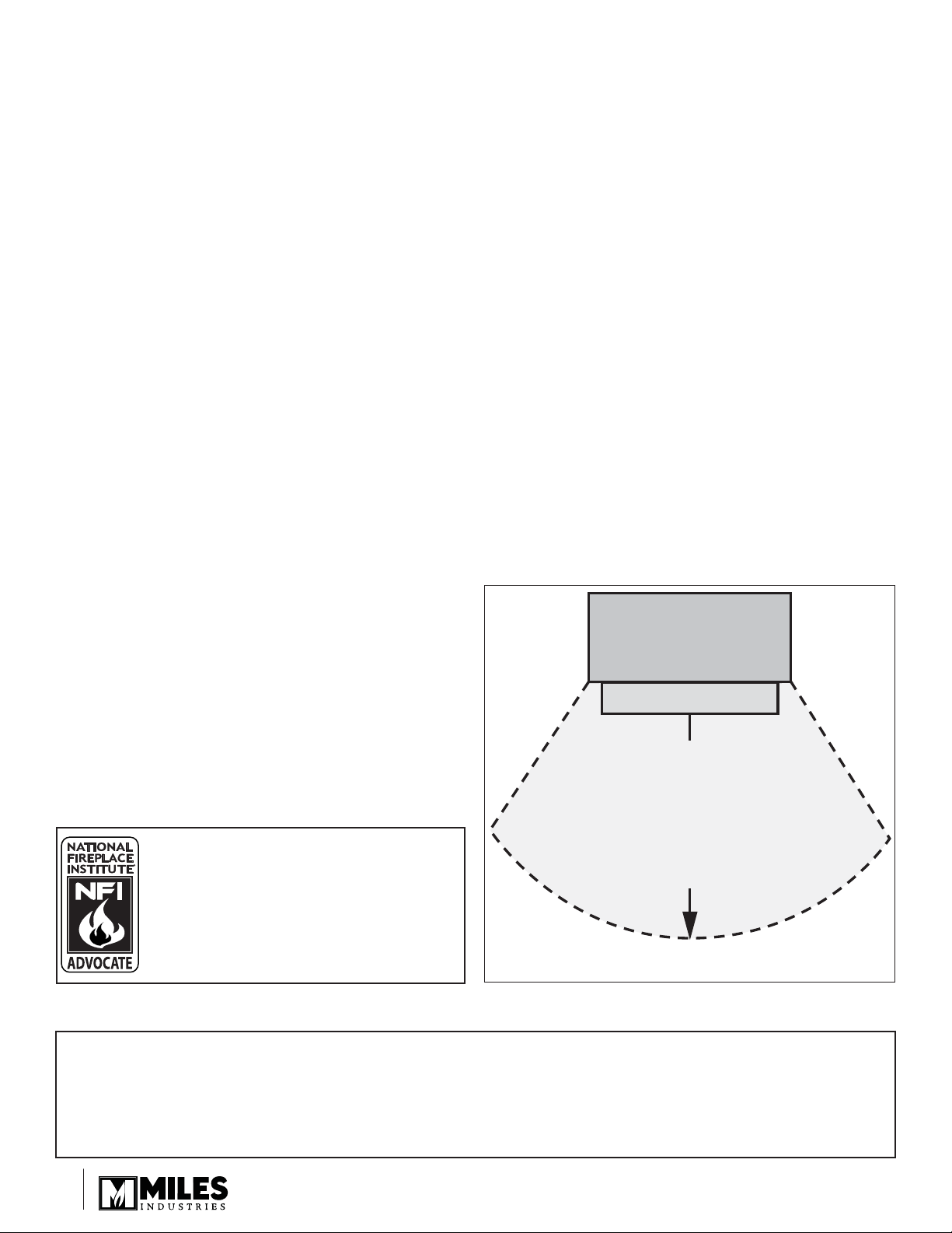
Fireplace
Do not put
furniture or other objects
in this space in front of
We recommend that our gas
hearth products be installed
and serviced by professionals
who are certifi ed in the United
States by NFI (National Fireplace
Institute®).
Designed and Manufactured by / for
Miles Industries Ltd.
190–2255 Dollarton Highway, North Vancouver, BC, CANADA V7H 3B1
Tel. 604-984-3496 Fax 604-984-0246
www.valorfi replaces.com
© Copyright Miles Industries Ltd., 2011
the replace:
36” (0.9 m)
Hearth
2
2

Table of Contents
Safety and Warning Information ..............................................................4
Specifi cations ............................................................................................7
Overview.....................................................................................................8
Dimensions ................................................................................................9
Framing ....................................................................................................10
Location ....................................................................................................11
Venting ......................................................................................................11
Co-Axial Venting ......................................................................................12
Co-Linear Venting ....................................................................................18
Appliance Preparation ............................................................................19
Gas Supply Installation ...........................................................................23
Liner Panels Installation .........................................................................24
Ceramic Logs Installation .......................................................................25
Window Refi tting & Checking ................................................................26
Remote Control Initial Set-up .................................................................26
Operation Check & Aeration Settings Adjustment ...............................27
Remote Control Handset Wall Holder Installation ................................27
Owner’s Information ................................................................................28
Remote Control Operation ......................................................................31
Options .....................................................................................................34
Lighting Instructions ...............................................................................35
Wiring Diagram ........................................................................................36
Approved Venting Components .............................................................37
◊
Warranty ...................................................................................................39
Replacement Parts ..................................................................................40
= Updated content
◊
33
Safety and Warning Information
READ and UNDERSTAND all instructions carefully
before starting the installation. FAILURE TO
FOLLOW these installation instructions may result in
possible fi re hazard and will void the warranty.
Prior to the fi rst fi ring of the fi replace, READ the
Owner’s Information section of this manual.
DO NOT USE this appliance if any part has been
under water. Immediately, CALL a qualifi ed service
technician to inspect the unit and to replace any part
of the control system and any gas control that has
been under water.
THIS UNIT IS NOT FOR USE WITH SOLID FUEL.
Installation and repair should be PERFORMED
by a qualifi ed service person. The appliance and
venting system should be INSPECTED before initial
use and at least annually by a professional service
person. More frequent cleaning may be required due
to excessive lint from carpeting, bedding, etc. It is
IMPERATIVE that the unit’s control compartment,
burner, and circulating air passageways BE KEPT
CLEAN to provide for adequate combustion and
ventilation air.
Always KEEP the appliance clear and free from
combustible materials, gasoline, and other fl ammable
vapors and liquids.
NEVER OBSTRUCT the fl ow of combustion and
ventilation air. Keep the front of the appliance CLEAR
of all obstacles and materials for servicing and proper
operation.
Due to the high temperature, the appliance should be
LOCATED out of traffi c areas and away from furniture
and draperies. Clothing or fl ammable material
SHOULD NOT BE PLACED on or near the appliance.
Children and adults should be ALERTED to the
hazards of high surface temperature and should STAY
AWAY to avoid burns or clothing ignition.
This unit MUST be used with a vent system as
described in this installation manual. NO OTHER vent
system or components MAY BE USED.
This gas fi replace and vent assembly MUST be
vented directly to the outside and MUST NEVER be
attached to a chimney serving a separate solid fuel
burning appliance. Each gas appliance MUST USE
a separate vent system. Common vent systems are
PROHIBITED.
INSPECT the external vent cap on a regular basis to
make sure that no debris, plants, trees, shrubs are
interfering with the air fl ow.
The glass door assembly MUST be in place and
sealed before the unit can be placed into safe
operation.
DO NOT OPERATE this appliance with the glass
door removed, cracked, or broken. Replacement of
the glass door should be performed by a licensed or
qualifi ed service person. DO NOT strike or slam the
glass door.
The glass door assembly SHALL ONLY be replaced
as a complete unit, as supplied by the fi replace
manufacturer. NO SUBSTITUTE material may be
used.
DO NOT USE abrasive cleaners on the glass door
assembly. DO NOT ATTEMPT to clean the glass door
when it is hot.
TURN OFF the gas before servicing this appliance.
It is recommended that a qualifi ed service technician
perform an appliance check-up at the beginning of
each heating season.
Any safety screen or guard removed for servicing
MUST BE REPLACED before operating this
appliance.
DO NOT place furniture or any other combustible
household objects within 36” of the fi replace front.
YOUNG CHILDREN should be CAREFULLY
SUPERVISED when they are in the same room as
the appliance. Toddlers, young children and others
may be susceptible to ACCIDENTAL CONTACT
BURNS. A physical barrier is recommended if there
are at risk individuals in the house. To restrict access
to a fi replace or stove, INST ALL AN ADJUSTABLE
SAFETY GATE to keep toddlers, young children and
other at risk individuals out of the room and away
from hot surfaces.
44
BE CAREFUL not to put any decorating objects
sensitive to heat to close above or around the
fi replace as it gets very hot when operating.
DO NOT use this heater as a temporary source of
heat during construction.
This appliance is a DOMESTIC ROOM-HEATING AP-
PLIANCE. It must not be used for any other purposes
such as drying clothes, etc.

Safety and Warning Information
Operating Your Fireplace for the First Time
When operating your new fi replace for the fi rst time,
some vapors may be released due to the burning of
curing compounds used in the manufacture of the
appliance. They may cause a slight odor and could
cause the fl ames to be the full height of the fi rebox, or
even slightly higher, for the fi rst few hours of operation.
It is also possible that these vapors could set off any
smoke detection alarms in the immediate vicinity.
These vapors are quite normal on new appliances. We
recommend opening a window to vent the room. After
a few hours use, the vapors will have disappeared and
the fl ames will be at their normal height.
State of California. Proposition 65 Warning.
Fuels used in gas, wood-burning or oil fi red appliances,
and the products of combustion of such fuels, contain
chemicals known to the State of California to cause
cancer, birth defects and other reproductive harm.
California Health & Safety Code Sec. 25249.6.
State of Massachusetts Carbon Monoxide
Detector/Vent Terminal Signage
Requirements
For all side wall horizontally vented gas fueled
equipment installed in every dwelling, building or
structure used in whole or in part for residential
purposes, including those owned or operated by the
Commonwealth and where the side wall exhaust
vent termination is less than seven (7) feet above
fi nished grade in the area of the venting, including
but not limited to decks and porches, the following
requirements shall be satisfi ed:
1. INSTALLATION OF CARBON MONOXIDE
DETECTORS. At the time of installation of the side wall
horizontal vented gas fueled equipment, the installing
plumber or gas fi tter shall observe that a hard wired
carbon monoxide detector with an alarm and battery
back-up is installed on the fl oor level where the gas
equipment is to be installed. In addition, the installing
plumber or gas fi tter shall observe that a battery
operated or hard wired carbon monoxide detector
with an alarm is installed on each additional level of
the dwelling, building or structure served by the side
wall horizontal vented gas fueled equipment. It shall
be the responsibility of the property owner to secure
the services of qualifi ed licensed professionals for the
installation of hard wired carbon monoxide detectors.
a. In the event that the side wall horizontally vented
gas fueled equipment is installed in a crawl space or
an attic, the hard wired carbon monoxide detector with
alarm and battery back-up may be installed on the next
adjacent fl oor level.
b. In the event that the requirements of this subdivision
can not be met at the time of completion of installation,
the owner shall have a period of thirty (30) days
to comply with the above requirements; provided,
however, that during said thirty (30) day period, a
battery operated carbon monoxide detector with an
alarm shall be installed.
2. APPROVED CARBON MONOXIDE DETECTORS.
Each carbon monoxide detector as required in
accordance with the above provisions shall comply
with NFPA 720 and be ANSI/UL 2034 listed and IAS
certifi ed.
3. SIGNAGE. A metal or plastic identifi cation plate
shall be permanently mounted to the exterior of the
building at a minimum height of eight (8) feet above
grade directly in line with the exhaust vent terminal for
the horizontally vented gas fueled heating appliance
or equipment. The sign shall read, in print size no less
than one-half (1/2) inch in size, “GAS VENT DIRECTLY
BELOW. KEEP CLEAR OF ALL OBSTRUCTIONS”.
4. INSPECTION. The state or local gas inspector of
the side wall horizontally vented gas fueled equipment
shall not approve the installation unless, upon
inspection, the inspector observes carbon monoxide
detectors and signage installed in accordance with the
provisions of 248 CMR 5.08(2)(a)1 through 4.
(b) EXEMPTIONS: The following equipment is exempt
from 248 CMR 5.08(2)(a)1 through 4:
1. The equipment listed in Chapter 10 entitled
“Equipment Not Required To Be Vented” in the most
current edition of NFPA 54 as adopted by the Board;
and
2. Product Approved side wall horizontally vented
gas fueled equipment installed in a room or structure
separate from the dwelling, building or structure used in
whole or in part for residential purposes.
55

Safety and Warning Information
(c) MANUFACTURER REQUIREMENTS - GAS
EQUIPMENT VENTING SYSTEM PROVIDED.
When the manufacturer of Product Approved side
wall horizontally vented gas equipment provides a
venting system design or venting system components
with the equipment, the instructions provided by the
manufacturer for installation of the equipment and the
venting system shall include:
1. Detailed instructions for the installation of the venting
system design or the venting system components; and
2. A complete parts list for the venting system design or
venting system.
(d) MANUFACTURER REQUIREMENTS - GAS
EQUIPMENT VENTING SYSTEM NOT PROVIDED.
When the manufacturer of a Product Approved side
wall horizontally vented gas fueled equipment does
not provide the parts for venting the fl ue gases, but
identifi es “special venting systems”, the following
requirements shall be satisfi ed by the manufacturer:
1. The referenced “special venting system” instructions
shall be included with the appliance or equipment
installation instructions; and
2. The “special venting systems” shall be Product
Approved by the Board, and the instructions for that
system shall include a parts list and detailed installation
instructions.
(e) A copy of all installation instructions for all Product
Approved side wall horizontally vented gas fueled
equipment, all venting instructions, all parts lists
for venting instructions, and/or all venting design
instructions shall remain with the appliance or
equipment at the completion of the installation.
66
Specifi cations
Approvals & codes
These appliances are certifi ed by ANSI Z21.88-2009/CSA
2.33-2009 American National Standard / CSA Standard
for Vented Gas Fireplace Heaters for use in Canada and
USA. These appliances are for installation directly venting
through an outside wall or through the roof.
Model 534ILN is for use with natural gas.
Model 534ILP is for use with propane gas.
Conversion between fuels may only be done using the
approved conversion kits listed in the section Options.
These appliances comply with CSA P4.1-09 Testing
method for measuring annual fi replace effi ciencies.
The installation must conform with local codes or, in
the absence of local codes with the National Fuel Gas
Code, ANSI Z223.1 or the Natural Gas and Propane
Installation Code CAN/CGA-B149. Only qualifi ed
licensed or trained personnel should install these
appliances.
These appliances, when installed, must be electrically
grounded in accordance with local codes or, in the
absence of local codes, with the National Electrical
Code, ANSI/NFPA 70 or the Canadian Electrical Code,
CSA C22.1.
Ratings
Model 534ILN 534ILP
Gas Natural Propane
Altitude (Ft.) 0-4500 *
Input Max. (Btu/h) 24,000 24,000
Input Min. (Btu/h) 6,500 13,000
Manifold pressure (in w.c..) 3.95 10.5
Min. Supply pressure (in. w.c.) 5.0 11.0
Max. Supply pressure (in. w.c.) 11.0 14.0
*Tested to CGA - 2.17-91 High Altitude Standard in
Canada. In the USA, installations may require deration
over 2000 feet—check local codes.
*High Altitude Installations
Input ratings are shown in BTU per hour and are
certifi ed without deration for elevations up to 4,500 feet
(1,370 m) above sea level.
For elevations above 4,500 feet (1,370 m) in USA,
installations must be in accordance with the current
ANSI Z223.1 and/or local codes having jurisdiction.
Heating value of gas in some areas is reduced to
compensate for elevation—consult your local gas utility
to confi rm.
For installations at elevations above 4,500 feet
(1,370 m) in Canada, please consult provincial and/or
local authorities having jurisdiction.
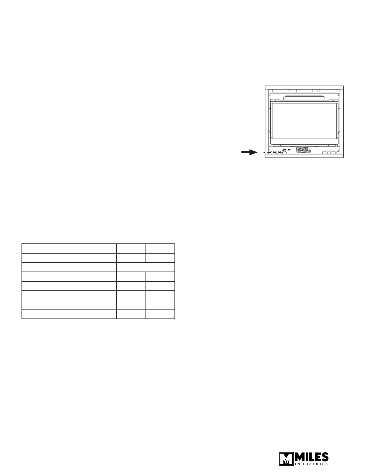
Supply Gas
Heater engine unit 534ILN is used with natural gas
installations.
Heater engine unit 534ILP is used with propane gas
installations.
The supply pressure must
be between the limits shown
in the table above.
The supply connection is ⅜
inch NPT.
The opening for the gas
supply line is at the left side
of the appliance.
X
X
Wall Thickness
The vent system (when horizontally terminated) is
approved to pass through combustible wall construction of
up to 14 inches (36 cm) thick.
A non-combustible wall can be any thickness up to the
maximum horizontal run of vent pipe allowed for the
particular installation—see Venting section.
Venting options
Direct vent installations (solid piping)
A list of all approved venting accessories is shown on
pages 37–38 of this manual.
NOTE: An 817VAK Vent Adapter is required in all cases
when using vent components other than Valor’s 551DVK
Standard Vent Terminal.
Direct Vent Co-Linear Installations (fl exible piping)
Converts the appliance outlet collars to accept two 3-inch
diameter fl ex liners for installation into existing solid-fuel
burning fi replaces and chimneys. Requires a co-linear
adapter at the appliance and either a co-linear terminal or
co-linear-to-co-axial adapter and terminal at the top of the
chimney. A list of approved venting accessories is shown
on pages 37–38 of this manual.
Floor/Hearth
This appliance is approved for installation directly on
combustible material such as plywood and so on. Vinyl,
carpet, and soft fl ooring require sheet metal extending the
whole width and depth under the appliance.
This appliance does not require a hearth. Combustible
fl ooring may extend up to the front of the unit.
77
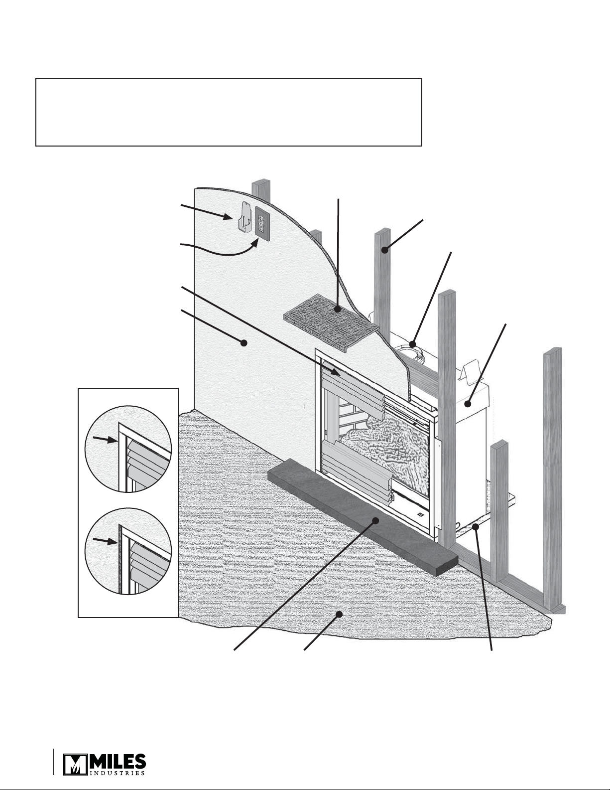
Overview
Note: A non-combustible cement board is required
above the fi replace when converting to higher input
using the 534HNK/534HPK conversion kits. Refer to the
instructions provided with the conversion kits for details.
Mantel—See Dimensions
section for mantel clearances
Remote Handset Wall Holder
Framing—See Framing section
Fire On/Off Wall Switch
(optional)
Required Front
(Contemporary Front 601SFB
shown—sold separately)
Wall Finish
May be combustible (see note
above). Finished wall surface
should be fl ush or slightly forward
of fi replace frame for most
applications. See instructions
provided with optional front trims.
Wall Finish
Flush
Field convertible
from top to rear
outlet
534IL
Forward
(534 recessed)
Hearth (if used) may be
combustible. Install the bottom
of the heater fl ush with the
top of fi nished hearth for most
applications. See instructions
provided with optional front trims.
Combustible Floor
Combustible framing allowed beneath fi replace.
When the appliance is installed directly on
carpeting, tile or other combustible material
other than wood fl ooring, the appliance shall be
installed on a metal or wood panel extending the
full width and depth of the appliance.
88
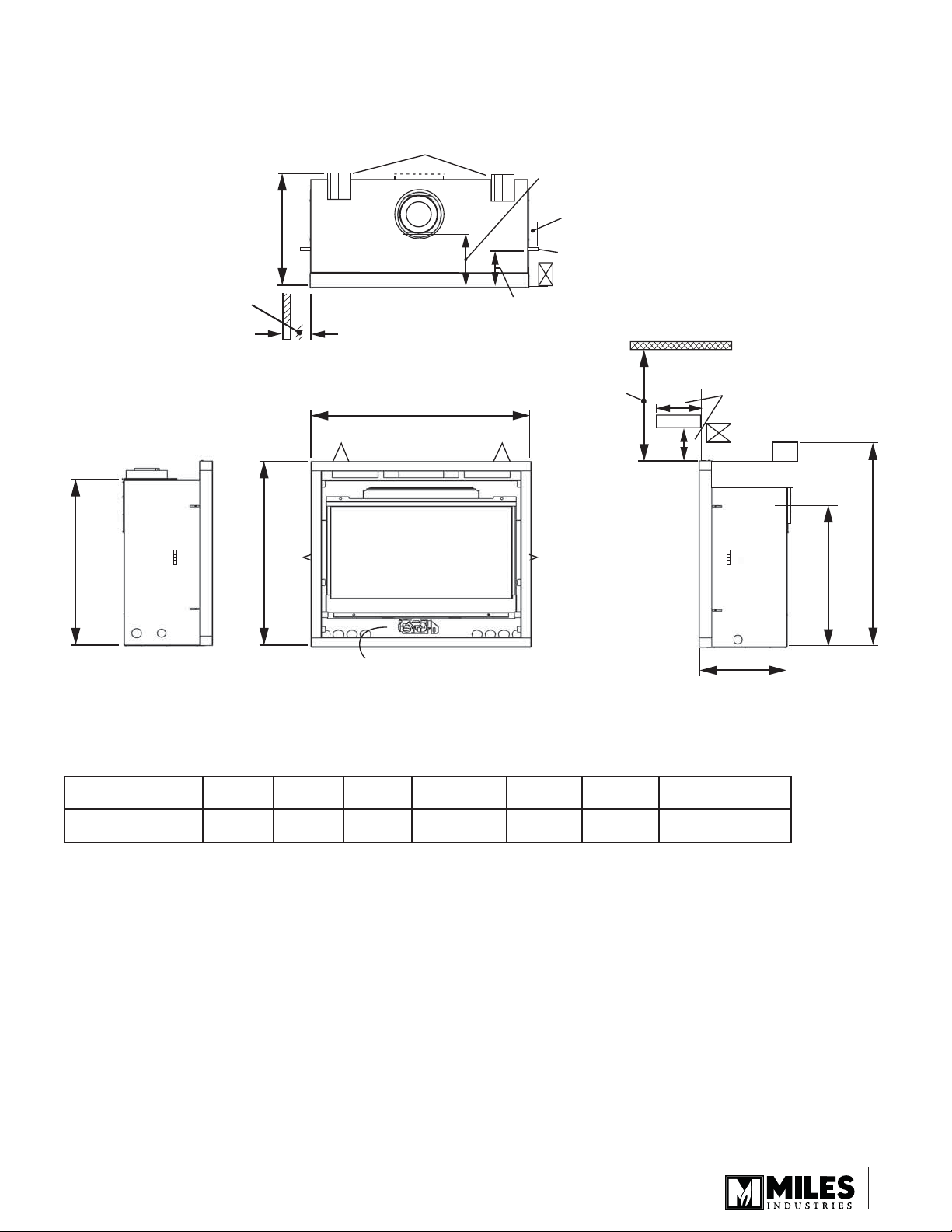
Dimensions
3” (75 mm) min.
To side wall from
inner frame
in front of
the appliance
16” (406 mm)
Stand-offs
32-3/16” (817 mm)
4-1/2”
(114 mm)
7” (180 mm)
From finished
wall front
to top vent
1-1/2”
(38 mm)
Stand-offs
36”
(914 mm)
min.
A
Mantel
See table
B
26-3/4” (679 mm)
Mantel depth “A”
Mantel clearance “B”
29-3/4” (756 mm)
X
Gas line
1”
(25 mm)2”(51 mm)3”(76 mm)
7”
(178 mm)8”(203 mm)9”(229 mm)
4”–5”
(102–127 mm)6”(152 mm)7”(178 mm)
10”
(254 mm)
11”
(279 mm)
12”
(305 mm)
14”
(355 mm)
8”–12” max.
(203–305 mm) max.
14”
(356 mm)
23-1/8” (587 mm)
to rear vent center
33-1/2” (850 mm)
99
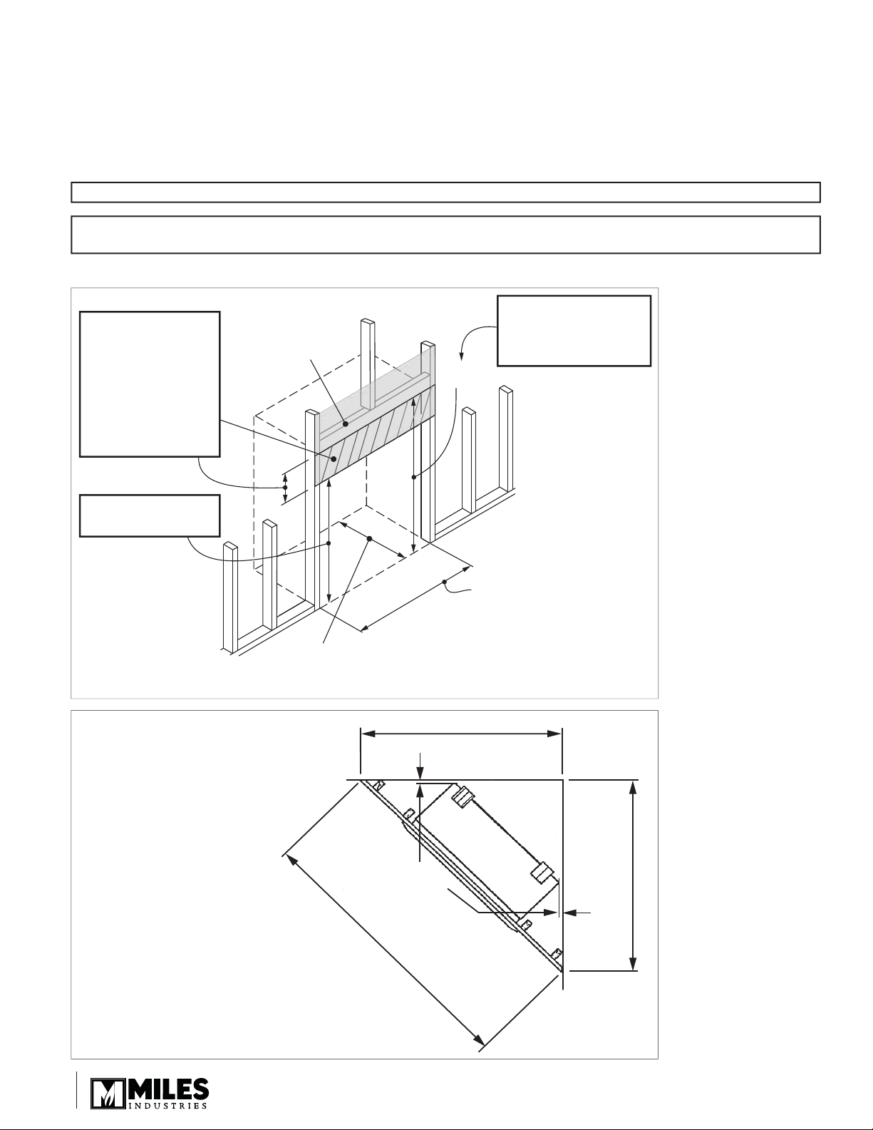
Framing
• A non-combustible hearth is not necessary in front of this appliance.
• Note that the unit is installed at the framing stage and fi xed to framing using support angles. See page 20. Wall
fi nish is then installed over the support angles up to the black frame on the unit.
NOTE: If using a 613CCB front, refer to the kit’s instruction manual for framing dimensions.
When the appliance is installed directly on carpeting, tile or other combustible material other than wood fl ooring, the
appliance shall be installed on a metal or wood panel extending the full width and depth of the appliance.
Header height MUST BE
WARNING!
The 9” (23 cm) space
between the appliance
and the header MUST
be non-combustible
(cement board or
similar) when using
the 534HNK or
534HPK kits.
Wall Finish
33-3/4” to
header
38-3/4” when using
the 534HNK or
534HPK High Input kits!
29-3/4” to wall finish
30-3/4” when using
645CFV Clearview Front
FRAMING DIMENSIONS
This is the framing
width. Wall finish
35-1/2”
16” min. straight out or off the top venting.
Allow for elbow if rear vent with rise.
to 32-3/16” wide.
45-1/2” (115.5 cm) min.
1-1/2”
64-1/4” (163.2 cm) min.
(38 mm)
min.
clearance
45-1/2” (115.5 cm) min.
FRAMING IN A CORNER
1010
Location
Venting
Vent Material
This unit is approved for installation using 4 x 6-5/8
inches approved co-axial direct vent pipes and accessories listed on pages 37–38 of this guide. Follow the
installation instructions supplied with the individual
venting accessories.
This unit may also be converted to co-linear venting
with two 3-inch pipes for use in solid-fuel burning
fi replaces and chimneys using approved adapters and
accessories listed on pages 37–38 of this guide.
Wall Thickness
The appliance vent is suitable for penetrating a
combustible wall assembly up to 14 inches in
thickness. A non-combustible wall can be of any
thickness up to the maximum horizontal run of vent
pipe allowed for the particular installation.
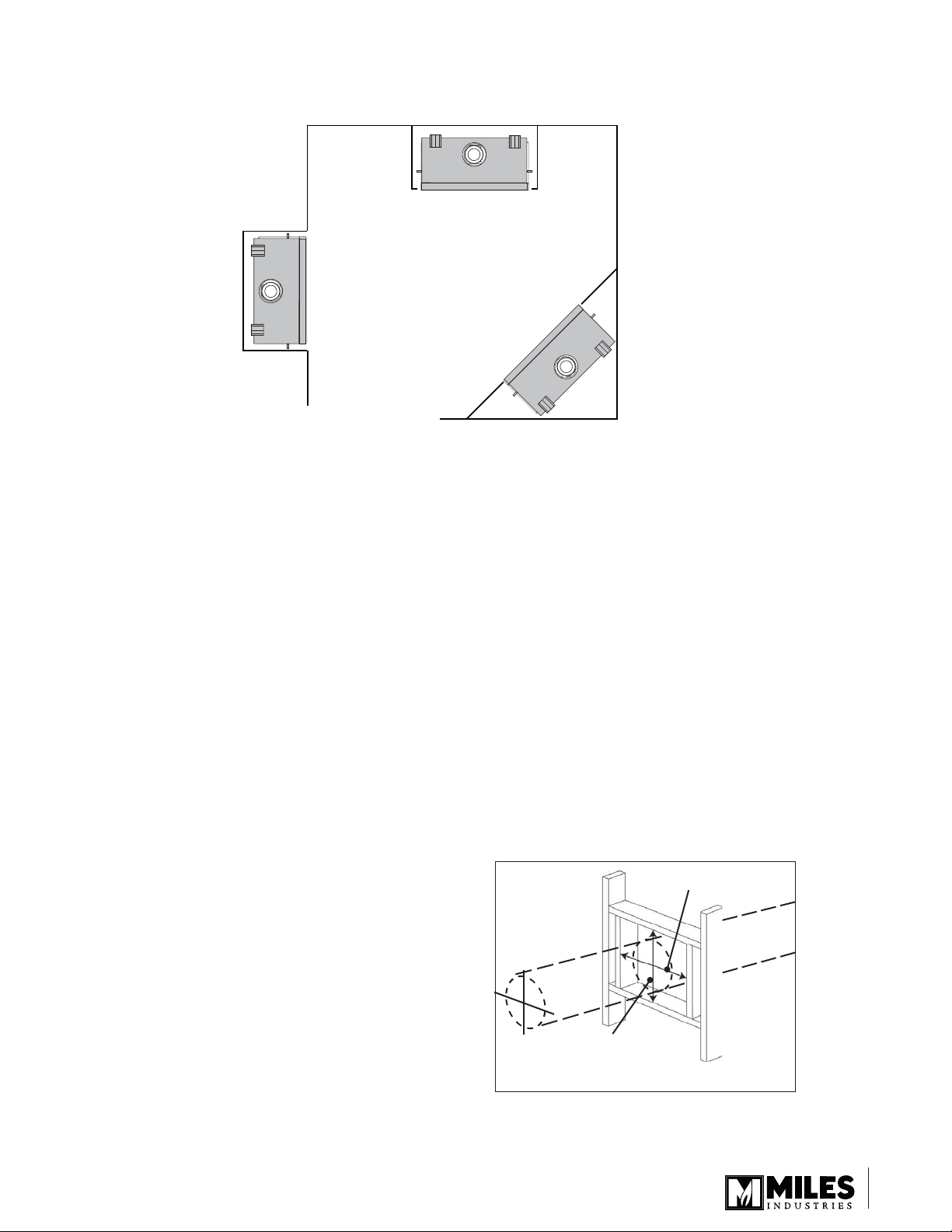
Vent Penetration through Walls & Ceilings
Combustible: When penetrating through combustible
walls and ceilings, frame a minimum of 10 inch x 10
inch opening and ensure that the insulation is kept
clear of the vent pipe using either a wall thimble
or an attic insulation shield. Follow the installation
instructions supplied with the individual venting
components.
Non-combustible: If the wall is totally non-combustible
(e.g. masonry block or concrete), mark for a 7 inch
circular hole.
In both cases, the center of the hole should line up with
the center line of the horizontal vent.
10” (254 mm)
Align the vent
center to the
center of the
frame
10” (254 mm)
Square opening
1111
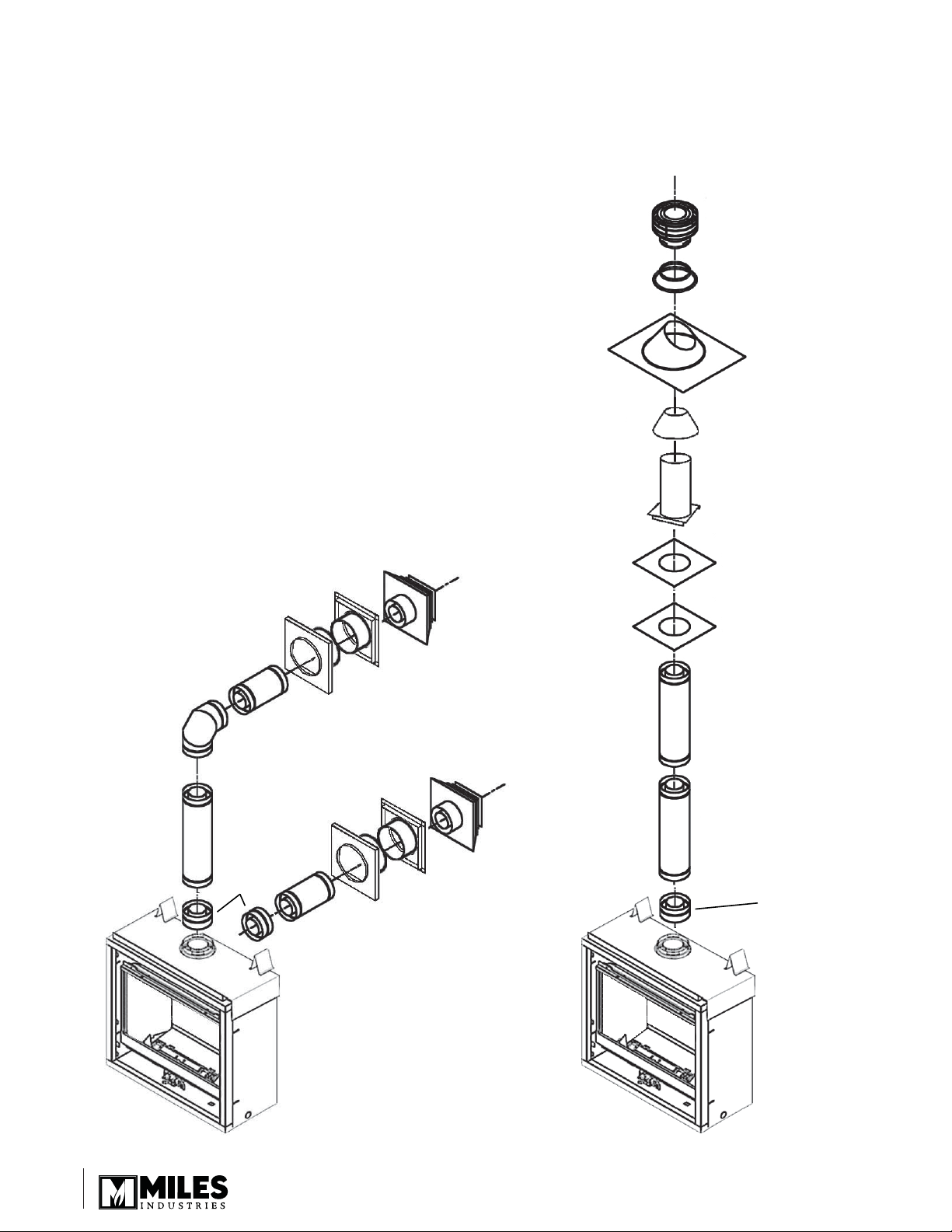
HORIZONTAL
TERMINATION
2-PIECE
WALL
THIMBLE
PIPE
LENGTH
PIPE
LENGTH
PIPE
LENGTH
817VAK
817VAK
PIPE
LENGTH
90˚ ELBOW
CEILING
FIRESTOP
ATTIC
FIRESTOP
ATTIC
INSULATION
SHIELD
FLASHING
STORM
COLLAR
VERTICAL
TERMINATION
Co-Axial Venting
Typical Co-Axial Venting Components
1212

Co-Axial Venting
Rear Vent with No Vertical Rise
The horizontal vent run cannot be extended by the use of any vent accessory pipes.
26” (66 cm) max.
vent length
(14” (36 cm) max.
enclosed within
combustible wall
cavity)
Use 835TG vent
guard with the
551DVK
termination
located at less
than 7’ (2.13 m)
above grade
23-1/8”
(58.7 cm)
Vent pipe max.
15” (38 cm)
after 45° elbow
Approved
side wall
termination
Approved
through wall
shield/thimble
Rear vent—no vertical rise
Corner rear vent—no vertical rise
Important Installer Notice – Weather Sealing & Vapor Barriers
It is the installer’s responsibility to ensure that vent installations through exterior walls are
caulked and weatherproofed in such a manner as to:
• Prevent rain water from entering the wall from the weather side by adequately caulking the
outer vent plate to the exterior wall surface.
• Prevent moisture inside the home from penetrating into the wall structure by ensuring the
inside wall plate is adequately sealed to the inside vapor barrier.
• Prevent rain water and moisture from entering the walls by sealing the joints between the
outer vent tube and the inner and outer wall plates.
We recommend the use of a high quality polyurethane sealant.
1313
Co-Axial Venting
V
G
A
Min. 72”
Max. 72”
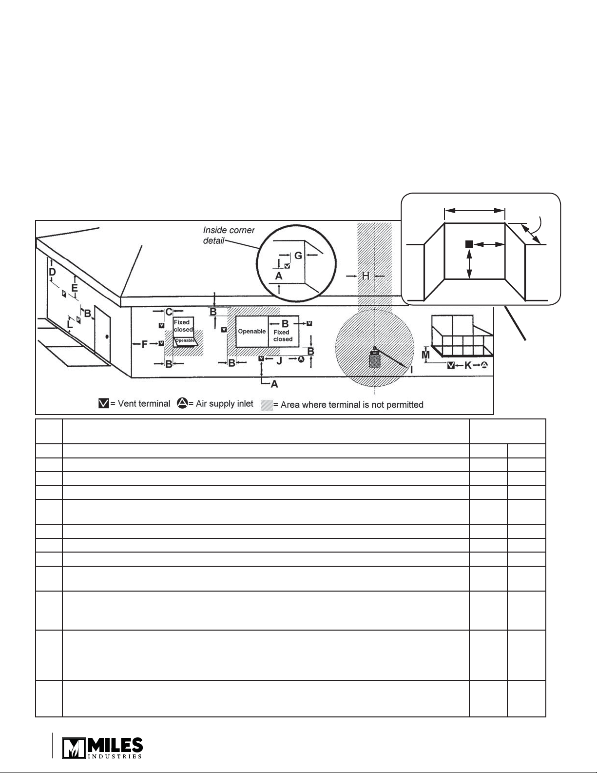
Horizontal Vent Termination Location
• The vent terminal must be located on an outside wall or through the roof.
• This direct vent appliance is designed to operate when an undisturbed airfl ow hits the outside vent terminal from
any direction.
• The minimum clearances from this terminal that must be maintained when located on an outside wall are shown
in fi gure below. Any reduction in these clearances could result in a disruption of the airfl ow or a safety hazard.
Local codes or regulations may require greater clearances.
• The vent terminal must not be recessed into a wall or siding.
• The vent terminal should be positioned where any snowdrifts will not cover it.
• 551DVK sidewall vent termination requires the 835TG terminal guard when
accessible—within 7’ of ground.
Alcove detail
(open on one
side) Normal
ceiling/soffi t
clearances
apply.
KEY VENT TERMINAL LOCATIONS - MINIMUM DISTANCES MINIMUM
CLEARANCE
Inches Cm
A Clearance above grade, verandah, porch, deck or balcony 12 30
B Clearance to window or door that may be opened 12 30
C Clearance to permanently closed window (recommended to prevent condensation on window) 12 30
D Vertical clearance to ventilated soffi t located above the terminal within a horizontal distance of
2 feet (60 cm) from the center-line of the terminal
E Clearance to unventilated soffi t1230
F Clearance to outside corner 12 30
G Clearance to inside corner 12 30
H Horizontal clearance to center-line of meter/regulator assembly located within 15 feet (4,6 m)
below the terminal
I Clearance to service regulator vent outlet 36 90
J Clearance to non-mechanical air supply inlet to the building or the combustion air inlet to any
other appliance
K Clearance to a mechanical air supply inlet 72 180
L Clearance above paved sidewalk or a paved driveway located on public property
Note: A vent must not terminate directly above a sidewalk or paved driveway, which is located
between two single-family dwellings and serves both dwellings
M Clearance under a verandah, porch, deck or balcony
Only permitted if veranda, porch, deck or balcony is fully open on a minimum of 2 sides
beneath the fl oor
Note: Local codes and regulations may require different clearances.
18 46
36 90
12 30
84 210
12 30
1414
 Loading...