

Valor Homeflame Dream, Homeflame Harmony, Homeflame Excelsior, Homeflame Masquerade, Homeflame Petrus Installation And Owner's Manual
...
Model 961
Inset live fuel effect gas fire
Incorporating the Valor Fires Control.
Fitted with one of the following fascia
Homeflame Dream
Homeflame Masquerade
Homeflame Excelsior
Homeflame Harmony
Homeflame Petrus
Homeflame Classica
(G.C. Number 32-032-88)
5136211/04
INSTALLATION AND OWNER GUIDE
© GDC Group Ltd. 2012
INSTALLER: Please leave this guide with the owner
We trust that this guide gives sufficient details to
enable this appliance to be installed and maintained
satisfactorily.
However, if further information is required, our Valor
Fires Technical Helpline will be pleased to help.
In the United Kingdom
Telephone 0844 879 35 88
(National call rates apply in the United Kingdom).
In the Republic of Ireland
Telephone 01 842 8222
GDC Group Ltd.
All rights reserved. No part of this publication may be reproduced in any material form
(including photocopying), stored in any medium by electronic means (including in any
retrieval system or database) or transmitted, in any form or by any means, whether
electronic, mechanical, recording or otherwise, without the prior written permission of
the copyright owner.
Applications for the copyright owner's permission to reproduce any part of this
publication should be made, giving details of the proposed use, to the following
address: The Marketing Communications Manager, GDC Group Ltd, Millbrook House,
Grange Drive, Hedge End, Southampton, SO30 2DF.
Warning: Any person who does any unauthorised act in relation to a copyright work
may be liable to criminal prosecution and civil claims for damages.
Valor, GDC Group Ltd., Millbrook House,
Grange Drive, Hedge End, Southampton, SO30 2DF.
www.valor.co.uk
Because our policy is one of constant development and improvement, details may vary slightly from
those given in this publication
THIS APPLIANCE IS FOR USE WITH NATURAL GAS (G20).
UNDER NO CIRCUMSTANCES IS THIS FIRE TO BE CONVERTED TO LPG.
AN LPG KIT DOES NOT EXIST FOR THIS GAS FIRE.
THIS APPLIANCE IS SUITABLE ONLY FOR INSTALLATION IN THE UNITED
KINGDOM (GB) AND THE REPUBLIC OF IRELAND (IE).
Page 2
© GDC Group Ltd. 2012
Safety First.
Page 3
© GDC Group Ltd. 2012
Valor fires are CE Approved and designed to meet the appropriate British Standards
and Safety Marks.
Quality and Excellence.
All Valor fires are manufactured to the highest standards of quality and excellence and
are manufactured under a BS EN ISO 9001 quality system accepted by the British
Standards Institute.
The Highest Standards
Valor Fires is a member of SBGI and HHIC (Heating and Hot water Industry Council)
that work to ensure high standards of safety, quality and performance.
Careful Installation
This gas fires must be installed by a competent GAS SAFE REGISTER engineer
(GAS SAFE REGISTER or CORGI engineer outside of UK) in accordance with our
installer guide and should not be fitted directly on to a carpet or floor of combustible
material.

INSTALLER GUIDE
Page 4
© GDC Group Ltd. 2012
INSTALLER GUIDE
FOR OWNER GUIDE SEE PAGES 47 TO 63

INSTALLER GUIDE
CONTENTS
Section Heading Page
INSTALLER GUIDE 4 - 46
OWNER GUIDE 47 - 63
1. SAFETY AND UNPACKING 7
2. APPLIANCE DATA, EFFICIENCY AND NOx 8
2.1 General information. 8
2.2 Efficiency. 8
2.3 NOx 8
3. GENERAL INSTALLATION REQUIREMENTS 9
3.1 Regulations, Standards and Law. 9
3.2 Ventilation requirements. 10
3.3 The Atmosphere sensing device (ASD). 10
3.4 Fireguard requirements. 10
3.5 Room considerations. 10
3.6 Chimney preparation. 10
3.8 The hearth. 11
3.9 Fireplace clearances. 12
3.10 Installation options. 14
3.10.1 Conventional fireplace and hearth. 14
3.10.1.1 ‘Hole-in-the-wall’ Installations. 15
3.10.2 Metal flue box and hearth. 15
3.10.3 Precast concrete or clay flue block system and hearth. 16
3.11 Flues. 16
4. PACK CONTENTS 17
5. FIREPLACE CHECK 20
5.1 Soundness for appliance attachment. 20
5.2 Fireplace flue pull. 20
6. IGNITION CHECK 21
7. GAS SUPPLY CONNECTION 21
8. PREPARING APPLIANCE FOR INSTALLATION 22
9. CONVECTION BOX INSTALLATION 24
9.1 Method 1 - Front fixing to fireplace surround. 24
9.2 Method 2 - Cable retention and floor fixing. 25
9.3 Sealing floor front - All installations. 27
© GDC Group Ltd. 2012
Continued on next page
Page 5

INSTALLER GUIDE
CONTENTS (Continued)
Section Heading Page
10. BURNER AND SUPPLY PIPE INSTALLATION 28
10.1 Burner and supply pipe installation. 28
10.2 Preliminary burner checks. 28
10.3 Inlet pressure check. 29
11. FITTING THE CERAMIC FUEL EFFECT 29
12. FITTING THE WINDOW FRAME ASSEMBLY 30
13. OPERATING AND SPILLAGE CHECKS 30
13.1 Checking the control settings. 30
13.2 Check for spillage. 31
13.3 Flame supervision and spillage monitoring system. 32
14. FASCIA FITTING 33
14.1 Homeflame Dream/Masquerade/Excelsior/Classica models. 33
14.2 Homeflame Harmony model. 35
14.3 Homeflame Petrus model. 35
15. FINAL REVIEW 37
16. SERVICING & PARTS REPLACEMENT 38
16.1 Checking the aeration setting of the burner. 38
16.2 To remove the ignition microswitch. 39
16.3 To remove the gas shut-off microswitch. 39
16.4 To remove the fascia. 39
16.5 To replace the control slide unit. 40
16.6 To replace the control slide button. 40
16.7 To remove and fit the window mounting frame and window assembly. 41
16.8 To remove the window assembly. 41
16.9 To remove the fuel effect. 42
16.10 To remove the ceramic side walls. 42
16.11 To remove the electronic ignition generator. 42
16.12 To remove the complete burner unit. 43
16.13 To remove the thermocouple interrupter block 43
16.14 To remove the pilot unit. 44
16.15 To remove the shut-off tap. 44
16.16 To remove the gas flow rate controller. 45
16.17 To replace the burner. 45
16.18 To remove the main burner injector. 46
16.19 To remove the appliance from the fireplace. 46
© GDC Group Ltd. 2012
Page 6

INSTALLER GUIDE
1. SAFETY AND UNPACKING
Installer
Before continuing any further with the installation of this appliance please read the
following guide to manual handling.
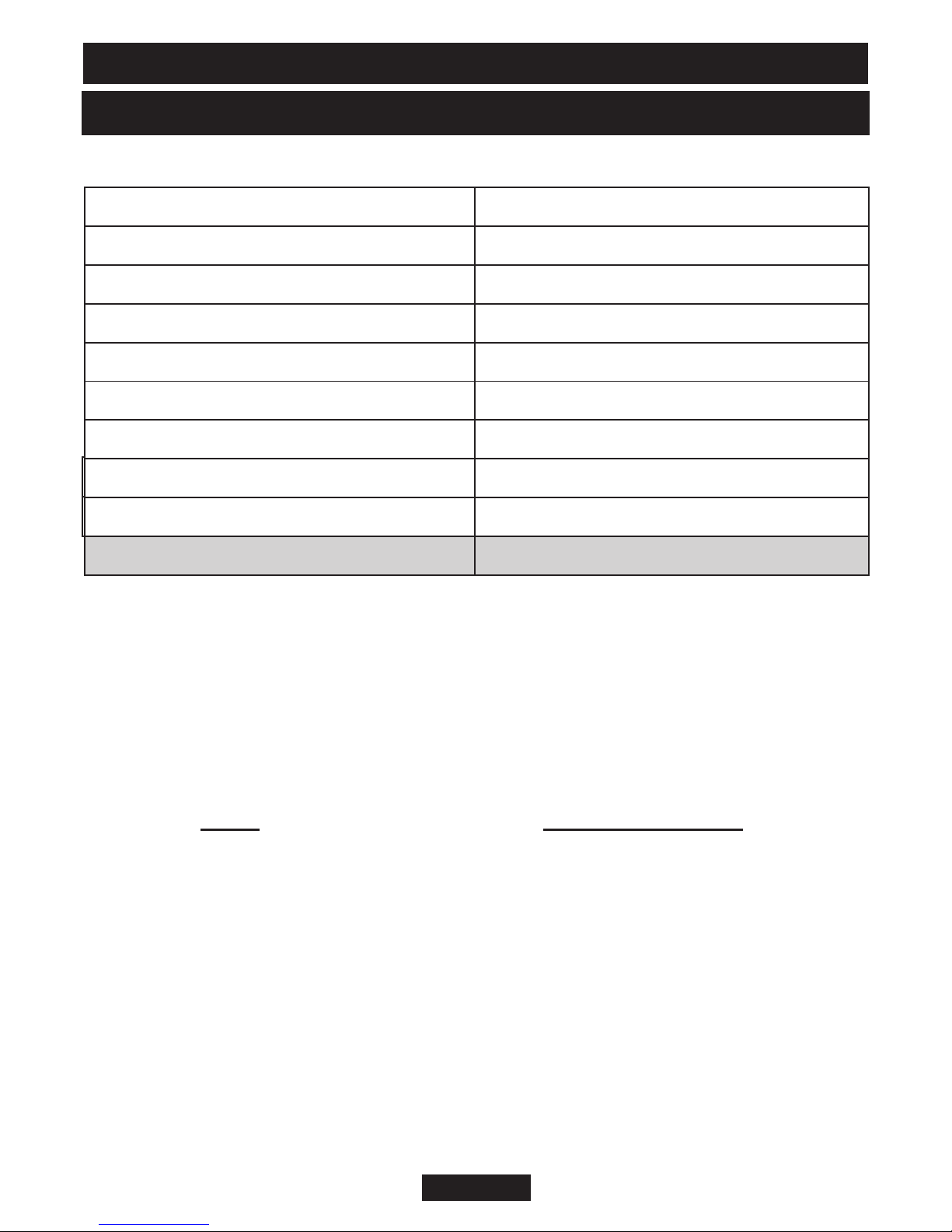
- The lifting weight (kg) of this appliance is as below:
Model
Dream/Masquerade/Excelsior 8.64 13.35 21.99
Harmony 8.64 3.55 12.19
Petrus 8.64 11.63 20.27
Classica 8.64 11.0 19.64
One person should be sufficient to lift the fire. If for any reason this weight is
considered too heavy then obtain assistance.
Heat Engine Firefront Combined Weight
- When lifting always keep your back straight. Bend your legs and not your back.
- Avoid twisting at the waist. It is better to reposition your feet.
- Avoid upper body/top heavy bending. Do not lean forward or sideways whilst
handling the fire.
- Always grip with the palm of the hand. Do not use the tips of fingers for support.
- Always keep the fire as close to the body as possible. This will minimise the
cantilever action.
- Use gloves to provide additional grip.
- Always use assistance if required.
This product uses fuel effect pieces and burner compartment walls containing
Refractory Ceramic Fibres (RCF), which are man-made vitreous silicate fibres.
Excessive exposure to these materials may cause irritation to eyes, skin and respiratory
tract. Consequently, it is important to take care when handling these articles to ensure
that the release of dust is kept to a minimum. To ensure that the release of fibres from
these RCF articles is kept to a minimum, during installation and servicing we
recommend that you use a HEPA filtered vacuum to remove any dust and soot
accumulated in and around the fire before and after working on the fire. When replacing
these articles we recommend that the replaced items are not broken up, but are sealed
within a heavy duty polythene bag, clearly labelled as RCF waste. RCF waste is classed
as a stable, non-reactive hazardous waste and may be disposed at a landfill licensed to
accept such waste. Protective clothing is not required when handling these articles, but
we recommend you follow the normal hygiene rules of not smoking, eating or drinking
in the work area and always wash your hands before eating or drinking.
This appliance does not contain any component manufactured from asbestos or
asbestos related products.
© GDC Group Ltd. 2012
Page 7
INSTALLER GUIDE
2. APPLIANCE DATA, EFFICIENCY AND NO
2.1 General information.
Gas Natural (G20)
Inlet Pressure 20mbar
Input - Max. (Gross) 5.00kW (17,060 Btu/h)
Input - Min. (Gross) 2.5kW (8,530 Btu/h)
Inlet Test Pressure (Cold) 20.0 ± 1.0mbar (8.0 ± 0.4in w.g.)
Gas Connection 8mm pipe
Burner Injector Cat 82 - 065
Pilot & Atmosphere Sensing Device Copreci Ref. O.D.S 21500/166
Ignition Electronic (Battery 9V PP3)
Aeration Setting See section 16.1
x
Under no circumstances is this fire to be converted to LPG. An LPG conversion kit
does not exist for this gas fire.
The appliance information label is located on the base of the fire underneath the
burner module.
2.2 Efficiency.
The efficiency of this appliance has been measured as specified in BS 7977 - 1 and
the result is as below:
Model Efficiency % (Gross)
961 80
The gross calorific value of the fuel has been used for this efficiency calculation. The
test data from which it has been calculated has been certified by Advantica
Certification services (0087). The efficiency value may be used in the UK
Government's Standard Assessment Procedure (SAP) for energy rating of dwellings.
The conversion of net efficiency to gross was achieved by multiplying the net
efficiency by the following conversion factor from Table E3 of SAP 2005, rounding
down to the nearest whole number.
© GDC Group Ltd. 2012
Page 8

INSTALLER GUIDE
Gas Conversion factor from net to gross efficiency
Natural Gas 0.901
2.3 NO
The 'Weighted' result for this appliance equates to NOx Class 2.
x
3. GENERAL INSTALLATION REQUIREMENTS
3.1 Regulations, Standards and Law.
The installation must be in accordance with these instructions.
For the user’s protection, in the United Kingdom it is the law that all gas appliances
are installed by competent persons in accordance with the current edition of the Gas
Safety (Installation and Use) Regulations. Failure to install the appliance correctly
could lead to prosecution. GAS SAFE REGISTER and CORGI require their members
to work to recognised standards.
In the United Kingdom the installation must also be in accordance with:
All the relevant parts of local regulations.
All relevant codes of practice.
The relevant parts of the current editions of the following British Standards:BS EN 1856 Part 1 - Chimneys - Requirements for metal chimneys.
BS 715 - Specification for metal flue boxes for gas-fired appliances not
exceeding 20kW.
BS EN 1858 - Chimneys - Components - Concrete flue blocks.
BS EN 1806 - Chimneys - Clay / ceramic flue blocks.
BS EN 1856 Part 1 - Chimneys - Requirements for metal chimneys.
BS 5440 Part 1 - Installation of flues.
BS 5440 Part 2 - Installation and maintenance of flues and ventilation for gas
appliances of rated input not exceeding 70 kW net (1st, 2nd
and 3rd family gases).
BS 6461 Part 1 - Masonry chimney & flues - Installation
BS 1251 - Fireplace components
BS 5871 Part 2 - Installation - Inset LFE gas fires
BS 6891 - Gas pipework installation
- In England and Wales, the current edition of the Building Regulations issued by the
Department of the Environment and the Welsh Office.
- In Scotland, the current edition of the Building Standards (Scotland) Regulations
issued by the Scottish Executive.
- In Northern Ireland, the current edition of the Building regulations (Northern Ireland)
issued by the Department of the Environment for Northern Ireland.
© GDC Group Ltd. 2012
Page 9

INSTALLER GUIDE
- In the republic of Ireland the installation must be carried out by a competent person
and also conform to the relevant parts of:
a) The current edition of IS 813 “Domestic Gas Installations”
b) All relevant national and local rules in force.
Where no specific instructions are given, reference should be made to the relevant
British Standard Code of Practice.
3.2 Ventilation requirements.
Normal adventitious ventilation is usually sufficient to satisfy the ventilation
requirements of this appliance. In GB reference should be made to BS 5871 Part 2
and in IE reference should be made to the current edition of IS 813 “Domestic Gas
Installations” which makes clear the conditions that must be met to demonstrate that
sufficient ventilation is available.
3.3 The Atmosphere sensing device (ASD).
The appliance is fitted with an A.S.D (Atmosphere sensing device). If the appliance
closes down after a period of operation for no apparent reason, the consumer should
be informed to stop using the appliance until the installation and appliance have been
thoroughly checked. The A.S.D will shut the appliance down if an unacceptable
amount of harmful products of combustion accumulate. Under no circumstances
should the A.S.D be altered or bypassed in any way. Only a genuine manufacturer’s
replacement part should be fitted. The individual A.S.D components are not
replaceable.
3.4 Fireguard requirements.
A fireguard complying with BS 8423 should be fitted for the protection of young
children, the elderly, the infirm and pet animals.
3.5 Room considerations.
3.5.1 This appliance must not be installed in any room that contains a bath or shower
or where steam is regularly present.
3.5.2 An extractor fan may only be used in the same room as this appliance, or in any
area from which ventilation for the appliance is taken, if it does not affect the safe
performance of the appliance. Note the spillage test requirements detailed further on
in this manual. If the fan is likely to affect the appliance, the appliance must not be
installed unless the fan is permanently disconnected.
3.5.3 Note that soft wall coverings (e.g. embossed vinyl, etc.) are easily affected by
heat. They may scorch or become discoloured when close to a heating appliance.
Please bear this in mind when installing.
3.6 Chimney preparation.
3.6.1 If the appliance is intended to be installed to a chimney that was previously used
for solid fuel, the flue must be swept clean prior to installation. All flues should be
inspected for soundness and freedom from blockages.
© GDC Group Ltd. 2012
Page 10
INSTALLER GUIDE
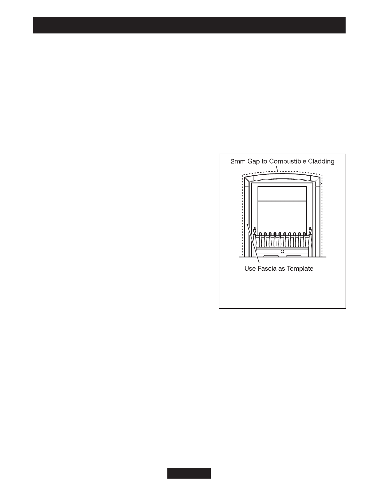
Figure 1. Removal of combustible
cladding (Fascia may differ from
that shown).
3.6.2 Any chimney damper or restrictor should be removed. If removal is not possible,
they must be secured in the open position.
3.7 Fireplace preparation.
3.7.1 If the fireplace opening is an underfloor draught type, it must be sealed to stop
any draughts.
3.7.2 The fireplace floor should be reasonably flat to ensure that the convection box
can be installed without it rocking and so that a good seal can be made at the bottom
front of the box.
3.7.3 The front face of the fireplace should be reasonably flat over the area covered
by the convection box top and side flange seals to
ensure good sealing. These faces should be made
good if necessary.
3.7.4 If the appliance is to be fitted against a wall
with combustible cladding, the cladding must be
removed from the area covered by the fascia. The
cladding must also not touch the fascia (See figure
1). We suggest that the actual fascia is used as a
template to mark the area for combustible cladding
removal and that this area is increased by at least
2mm all round.
3.7.5 If the fireplace opening is greater than the
acceptable dimensions given in this guide, do not
use the back of a fire surround or marble to reduce
the opening. This may cause cracking of the
surround back or marble.
3.8 The hearth.
The appliance must be mounted behind a non-combustible hearth unless the
conditions of section 3.10.1.1 are met (N.B. conglomerate marble hearths are
considered as non-combustible). The appliance can be fitted to a purpose made
proprietary class “O”-150°C surround. The hearth material must be at least 12mm
thick. The periphery of the hearth (or fender) should be at least 50mm above floor
level to discourage the placing of carpets or rugs over it.
The surface of the hearth must be sufficiently flat to enable the bottom of the front
surround and the bottom front cover to be aligned horizontally. Any excessive
unevenness (uneven tiles, Cotswold stone, etc.) should be rectified.
The appliance must not stand on combustible materials or carpets.
© GDC Group Ltd. 2012
Page 11
INSTALLER GUIDE
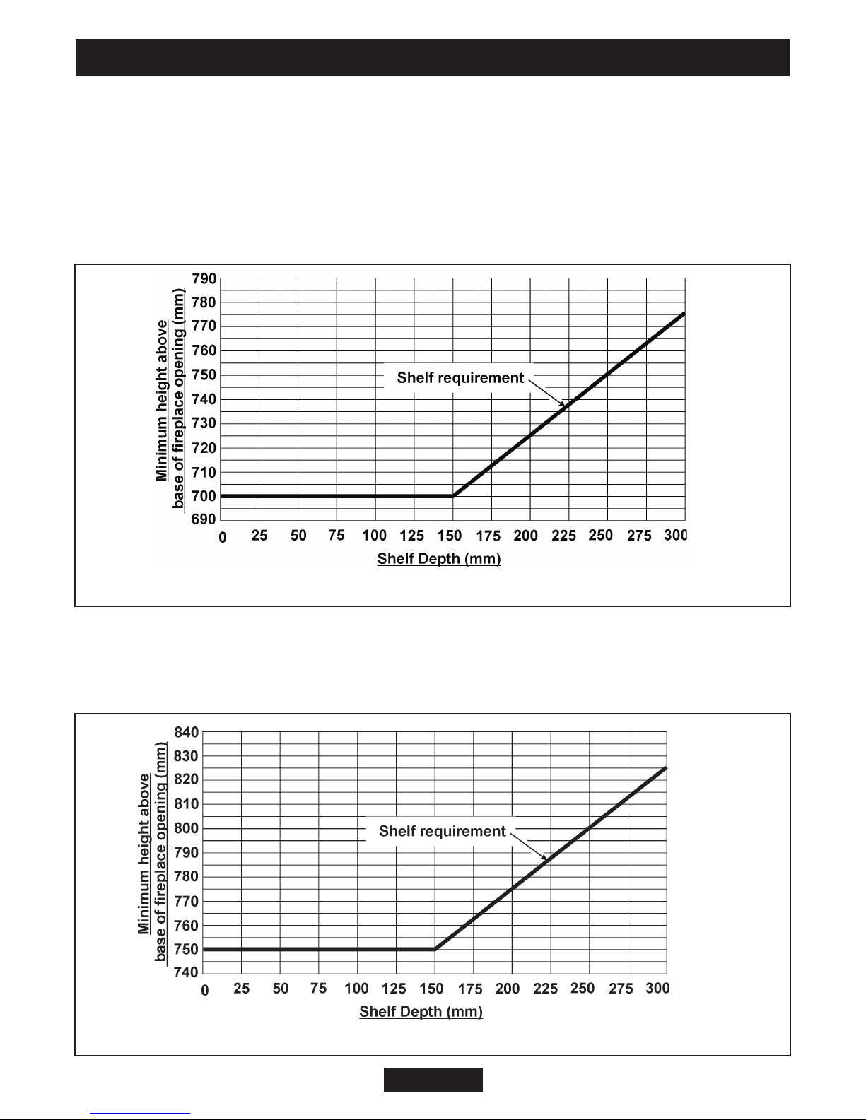
Figure 2. Combustible shelf clearances
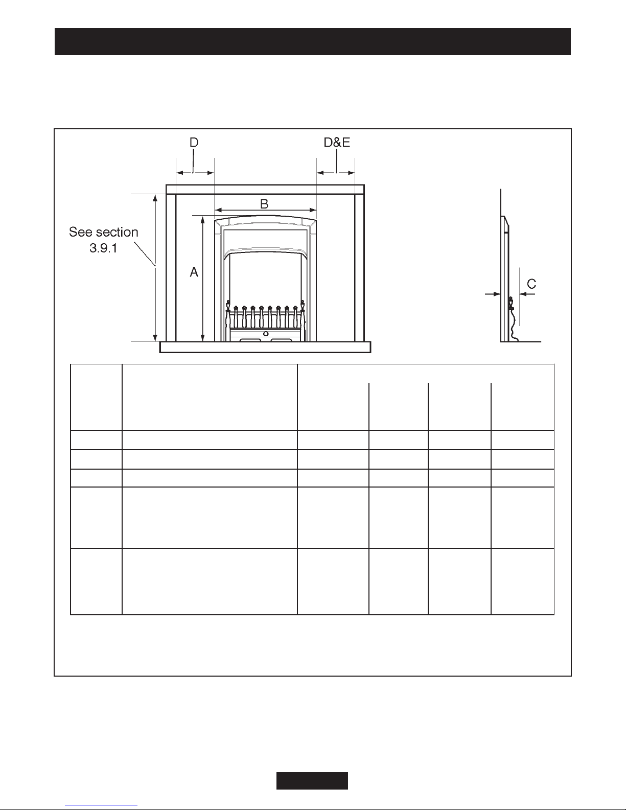
Figure 3. Combustible shelf clearances
3.9 Fireplace clearances.
3.9.1 The minimum height from the base of the fireplace opening to the underside of
any shelf made from wood or other combustible materials is detailed below.
For Dream, Masquerade, Excelsior, Classica and Homeflame Harmony models -
• For a shelf up to 150mm deep: Minimum height = 700mm.
• For a shelf deeper than 150mm: 700mm + 12.5mm for every 25mm depth over
150mm (See Figure 2).
For Homeflame Petrus models -
• For a shelf up to 150mm deep: Minimum height = 750mm.
• For a shelf deeper than 150mm: 750mm + 12.5mm for every 25mm depth over
150mm (See Figure 3).
© GDC Group Ltd. 2012
Page 12
INSTALLER GUIDE
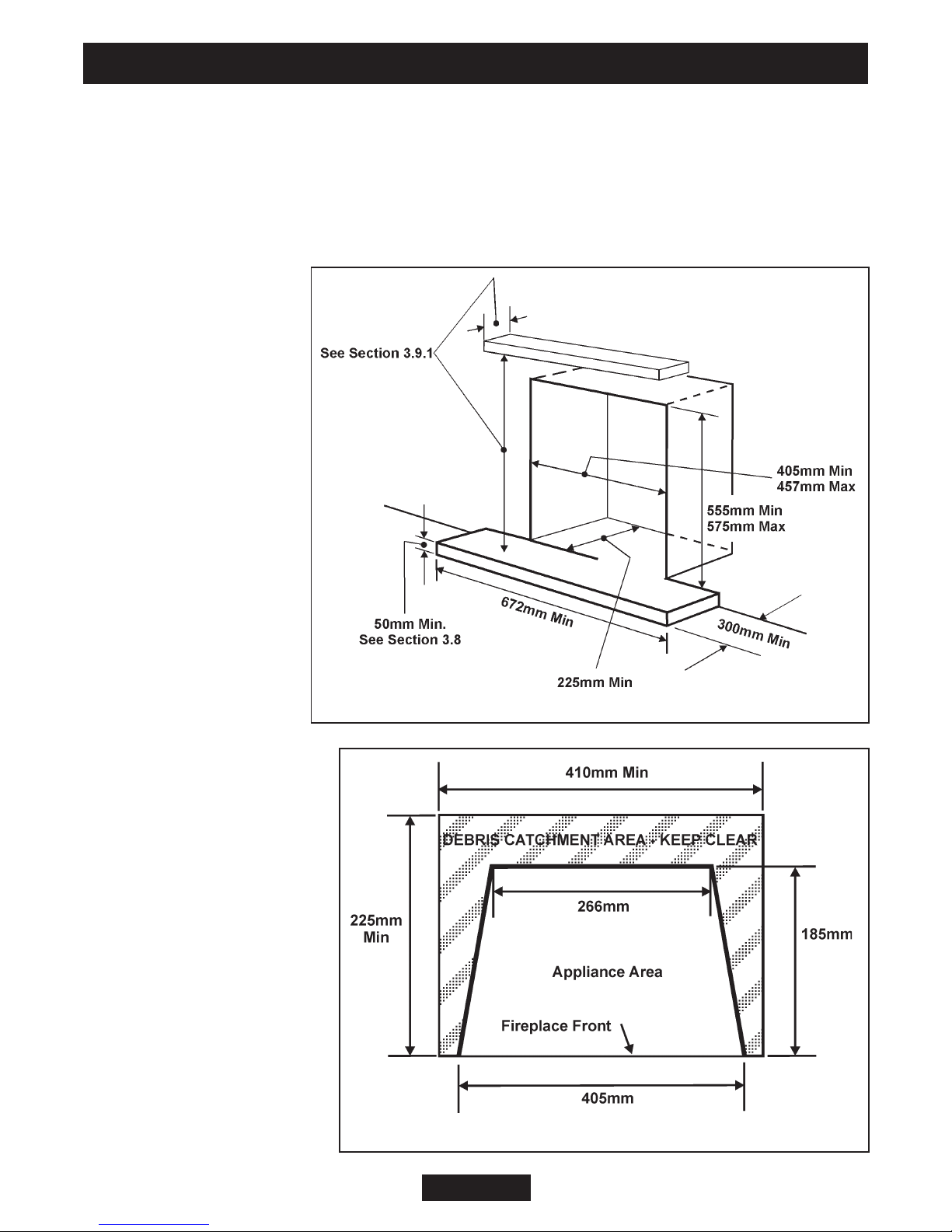
Figure 4. Appliance dimensions and clearances (The fascia may differ from that
shown and dimensions are subject to manufacturing tolerances)
Key Description
Model
Dream,
Masquerade,
Excelsior
Harmony Petrus Classica
A Height (mm)
636 631 636 631
B Width (mm)
518 546 518 540
C Depth into room (mm)
94 64 94 80
D
Minimum mandatory clearance to
combustible surfaces projecting
beyond the front of appliance (mm)
100 100 100 100
E
Recommended clearance to non‐
combustible surfaces for access
purposes (mm)
50 50 50 50
3.9.2 The minimum allowable distance from the outside of the appliance fascia to a
corner wall having combustible material or any other combustible surface which
projects beyond the front of the appliance is shown in figure 4. A 10mm access
clearance from a non-combustible surface is necessary at the left side.
© GDC Group Ltd. 2012
Page 13
INSTALLER GUIDE
Figure 5. Hearth and fireplace opening dimensions
Figure 6. Fireplace area.
3.10 Installation options.
In the United Kingdom, as supplied, the appliance can be installed in the
following situations: -
3.10.1 Conventional fireplace and hearth.
To a fireplace complete with surround and hearth as shown in figure 5 and complying
with BS1251 after removal of the fireback and sufficient material behind the fireback
for a debris catchment
space. The required
fireplace, hearth, debris
catchment area and
clearance dimensions
are shown in figure 6.
© GDC Group Ltd. 2012
Page 14
INSTALLER GUIDE
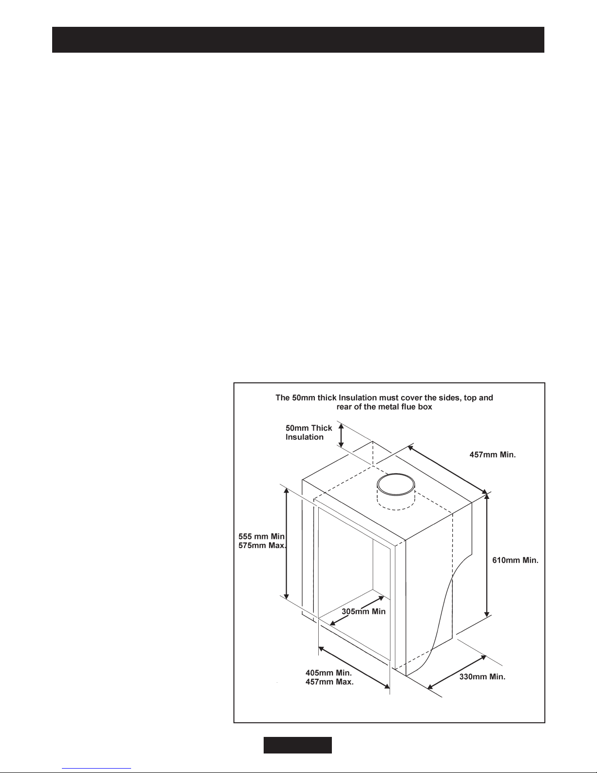
Figure 7. Metal flue box dimensions
3.10.1.1 ‘Hole-in-the-wall’ Installations.
- It is recommended that a hearth should be installed as in section
3.8.
- Homeflame Dream/Masquerade/Excelsior/Classica firefront
If a reduced depth hearth is fitted, the fire must be installed so that the distance
from the base of the fireplace opening in the wall to the finished floor level is at least
100mm. It is recommended that the reduced hearth has a depth from the fixing plane
of the fire of 100mm minimum. This is necessary to support the lower front casting.
Where there is no floor covering or carpet and the floor is of a type that is likely to be
covered in such a way in the future then the distance from the base of the fireplace
opening in the wall to the floor level should be increased to at least 175mm.
- Homeflame Harmony firefront
If a hearth is not fitted, the fire must be installed so that the distance from the
base of the fireplace opening in the wall to the finished floor level is at least 100mm.
Where there is no floor covering or carpet and the floor is of a type that is likely to be
covered in such a way in the future then the distance from the base of the fireplace
opening in the wall to the floor level should be increased to at least 175mm.
3.10.2 Metal flue box and hearth.
The appliance can be installed to a fireplace incorporating a metal flue box complying
with the constructional requirements of the current edition of BS 715 and with a flue
conforming to BS EN 1856 part
1. The dimensions of the flue
box must conform to those
shown in figure 7.
The top, sides and rear surface
of the metal flue box must be
covered with a 50mm layer of
mineral wool or equivalent
insulation (See figure 7).
Important Note: Where the
flue box has a base sheet that
is single wall (i.e. a single
metal sheet) the flue box must
be mounted on a noncombustible hearth. The hearth
material must be at least 12mm
thick.
© GDC Group Ltd. 2012
Page 15
INSTALLER GUIDE
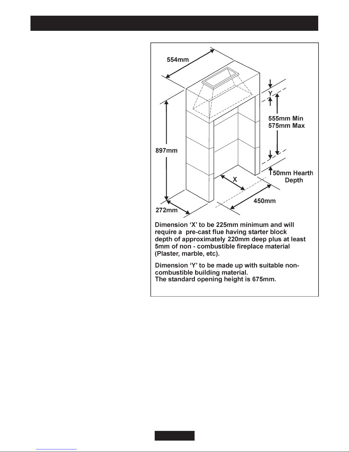
Figure 8. Precast or clay flue block system
3.10.3 Precast concrete or clay
flue block system and hearth.
The appliance can be installed to a
precast concrete or clay flue block
system conforming to BS EN 1858
with dimensions as in figure 8.
BS 1289 part 1 recommends there
should be an air space or insulation
between the flue blocks and the
plaster because heat transfer may
cause cracking on directly
plastered flues. However, generally
this appliance is suitable for
installations under all
circumstances unless there is a
history of cracking problems.
Remember that faults such as
cracking may be caused by poorly
built and restrictive flues, e.g.
mortar extrusions, too many bends,
flue heights below three metres,
restrictive terminations etc.
3.11 Flues.
1. Suitable flues and minimum flue
sizes are as follows:
It should be noted that, as with
many appliances, sharp bends or horizontal runs in metal flues at the top of the
system can be a cause of problems in these types of installation.
- 225mm x 225mm conventional brick flue.
- 175mm diameter lined brick or stone flue.
- 200mm diameter factory made insulated flue manufactured to BS4543 Part 2.
- 175mm diameter flue pipe. See BS6461 Part 1 for suitable materials.
- Single wall, twin wall or flexible flue liner with a minimum diameter of 125mm. The
materials to be used are stainless steel or aluminium as specified in
BS EN 1856 Part 1. The liner must be sealed to the surrounding area above the
fireplace opening and to the top of the chimney. An approved terminal must be fitted.
- A properly constructed precast concrete or clay flue system conforming to BS1289
or BS EN 1858. This system is only suitable if the conditions stated in section
are met.
© GDC Group Ltd. 2012
Page 16
3.10.3

INSTALLER GUIDE
2. The flue must conform to BS 5440: Part 1 in design and installation.
The flue, measured from the bottom of the fireplace opening to the bottom of the
terminal, shall be not less than 3m in actual vertical height. When calculated in
accordance with BS 5440: Part 1 Annex A, the minimum equivalent height of the flue
shall be 2.0m of 125mm dia. flue pipe.
3. The flue must not be used for any other appliance or application.
4. Proprietary terminals must comply with BS 715 or BS 1289. Any terminal or
termination must be positioned in accordance with BS 5440 Part 1 to ensure that the
products of combustion can be safely dispersed into the outside atmosphere. Where
the appliance is connected to an unlined brick chimney it is generally unnecessary for
the chimney pot to be replaced or for a terminal to be fitted unless the flue has a
diameter smaller than 170mm.
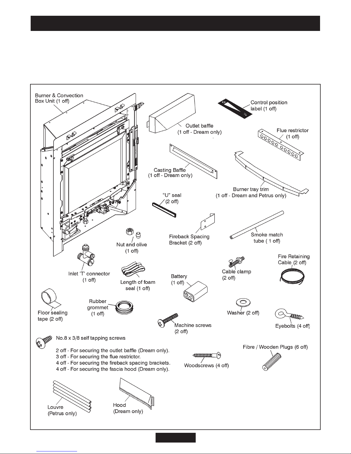
4. PACK CONTENTS
The items required for this appliance are packed in sections.
Section 1 - Fire unit contains:
1 Burner and convection box unit.
1 Burner tray trim (Homeflame Dream and Homeflame Petrus only).
1 Outlet baffle for the convected air outlet (Homeflame Dream only).
2 Tapping Screws for outlet baffle (Homeflame Dream only).
1 Nut and olive for 8mm inlet pipe.
1 ‘T’ connector and pressure test point.
1 Flue restrictor.
3 Tapping Screws (For flue restrictor).
2 Small “U” seals (For convection box side flanges).
2 Strips of floor sealing tape.
6 Fibre / wooden plugs.
4 Woodscrews.
2 Fire retaining cables.
2 Cable clamps.
4 Eyebolts.
1 Rubber grommet (For rear of convector box).
2 Machine screws (For fascia hanging).
2 Washers for fascia hanging (Homeflame Dream and Homeflame Petrus only)
1 PP3 Battery.
1 Smoke match tube.
2 Fireback spacing brackets.
4 Tapping Screws (For fireback spacing brackets).
2 Lengths of self adhesive foam seal.
1 Literature pack (Not shown).
1 Ceramic fuel effect set (Not shown).
© GDC Group Ltd. 2012
Page 17
INSTALLER GUIDE
Figure 9. Pack contents (Items are not to scale)
4 Tapping screws for fascia hood (Dream, Masquerade, Excelsior only).
1 Firefront casting baffle (Dream, Masquerade, Excelsior only).
1 Slider control position label.
1 Upper louvre assembly (Homeflame Petrus only).
1 Hood Dream only).
© GDC Group Ltd. 2012
Page 18
INSTALLER GUIDE
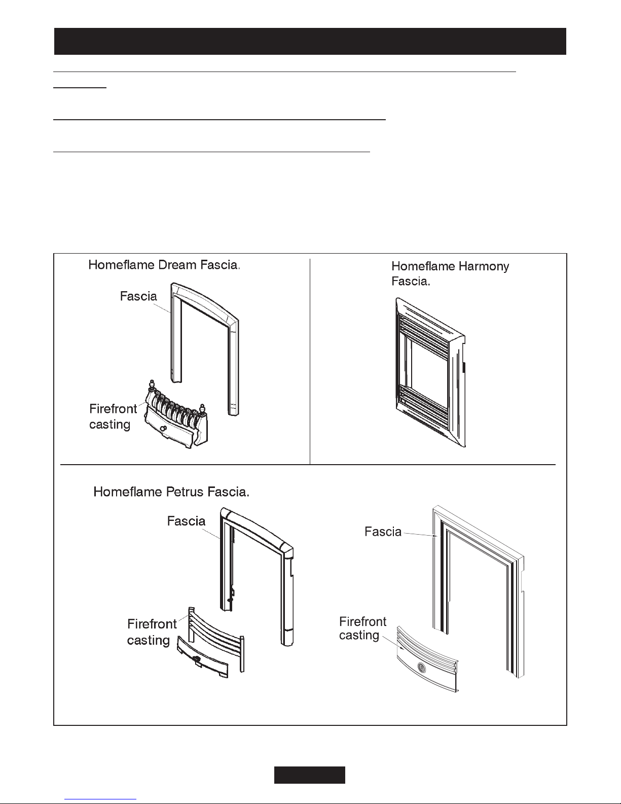
Homeflame Classica Fascia.
Section 2 - “Homeflame Dream, Masquerade, Excelsior, Classica” fascia pack
contains:
1 Fascia and firefront casting.
Section 2 - “Homeflame Harmony” fascia pack contains:
1 Fascia.
Section 2 - “Homeflame Petrus” fascia pack contains:
1 Fascia and firefront casting.
Carefully remove all the contents. Take special care in handling the ceramic pieces.
Take care not to bend or distort the slide control linkage.
Check that all the listed parts are present and in good condition.
Figure 9. Pack contents continued (Items are not to scale)
© GDC Group Ltd. 2012
Page 19

INSTALLER GUIDE
5. FIREPLACE CHECK
5.1 Soundness for appliance attachment.
Two primary methods of retaining the appliance are provided: -
1) By fixing to the fireplace front surround.
2) Using concealed tension cables fixed to the rear of the fireplace opening together
with secondary fixing to the fireplace floor.
The methods are detailed in section 9 of this manual. Before selecting the retention
method, consult with the customer. Method 2 is provided for instances where drilling
holes in the front surface of the fireplace surround is unacceptable to the customer or
otherwise impractical. N.B. It is unwise to attempt to drill into marble without the
proper tools and equipment.
If method 1 is chosen, make sure that the front surround area is sound enough to take
the fibre / wooden plugs and woodscrews. If necessary, make sound with suitable
cement.
If method 2 is chosen, make sure that the areas at the back and towards the centre of
the fireplace floor are sound enough to take the eyebolts and screws. If these areas
have deteriorated due to prolonged use, they should be made sound with suitable
cement.
5.2 Fireplace flue pull.
Close all doors and windows in the room in which the appliance is to be installed.
After confirming with a match that smoke is drawn into the flue, light a 13 gram smoke
pellet and check that there is a definite flow through the flue. Verify outside that the
smoke exits from one terminal only and that the termination is suitable. Observe,
where possible, upstairs rooms and loft spaces for signs of escaping smoke indicating
a defective flue. If there is not a definite flow warm the flue for a few minutes and
repeat the smoke pellet test. If there is still no definite flow the flue may need remedial
work – Do not fit the appliance until there is a definite flow through the flue.
© GDC Group Ltd. 2012
Page 20
 Loading...