

RADIANT / CONVECTOR GAS FIRE
MODEL 426
(GC 32 811 40)
INSTALLATION & SERVICING INSTRUCTIONS
INSTALLER: Please leave these instructions with the owner
We trust that these instructions give sufficient details to enable this appliance to be installed and maintained
satisfactorily. However, if further information is required, our
advice lin e will b e p le ased to he lp. Ring 0345
626 341 (Local call rates apply)
600A515/07
THIS APPLIANCE
IS FOR USE WITH
NATURAL GAS
(G20) AT A SUPPLY
PRESSURE OF
20mbar (8in w.g.)
THIS APPLIANCE
IS FOR USE IN
THE UNITED
KINGDOM (GB)
AND
THE REPUBLI C
OF IRELAND (IE)
2
LIST OF CONTENTS
Page
Overall dimensions …..................................................................................................................................................................... 2
Appliance data .............................................................................................................................................…...................……. 3
General installation requirements..........................................................................................................................................…… 3
Fireplace & hearth..........................................................................................................................................................…. 4
Wall mounted.................................................................................................................................................................…. 4
Precast flues...................................................................................................................................................................….. 4
Metal flue box.................................................................................................................................................................…. 4
Flues................................................................................................................................................................................. ….4
Unpacking & pre-installation preparation..................................................................................................................... .....…........ 6
Carton contents..............................................................................................................................................................….. 6
Fireplace flue pull check................................................................................................................................................….. 6
Appliance preparation.....................................................................................................................................................…..6
Ignition spark check..........................................................................................................................................................…7
Feet assembly (For floor mounted appliances)..............................................................................................................… 7
Closure plate fitting.........................................................................................................................................................….8
Appliance installation..............................................................................................................................................................……… 9
Installing to hearth..........................................................................................................................................................…..9
Wall mounting.................................................................................................................................................................….9
Gas supply connection...................................................................................................................................................…..9
Coal & window fitting......................................................................................................................................................…9
Full operating checks............................................................................................................................................................……… 10
Control setting checks...................................................................................................................................................….10
Reference pressure check..........................................................................................................................................….…10
Final assembly & checks.......................................................................................................................................................……... 10
Outer case fitting........................................................................................................................................................… ....10
Spillage check.............................................................................................................................................................….....10
Flame supervision & spillage monitoring system check................................................................................................. 11
Final review................................................................................................................................................................…......11
Servicing & parts replacement.............................................................................................................................................……..... 12
Window removal....................................................................................................................................................…..... .12
Outer case removal........................................................................................................................................................….12
Coal removal...................................................................................................................................................................…12 Gas
tap removal..............................................................................................................................................................….12
Burner, pipes & pilot removal........................................................................................................................................... 13
Injector removal............................................................................................................................................................…..13 Gas
supply pipe disconnection......................................................................................................................................… 13
Piezo generator removal.................................................................................................................................................… 13
Control tap greasing........................................................................................................................................................…13
Replacement parts - short list........................................................................................................................................… 14
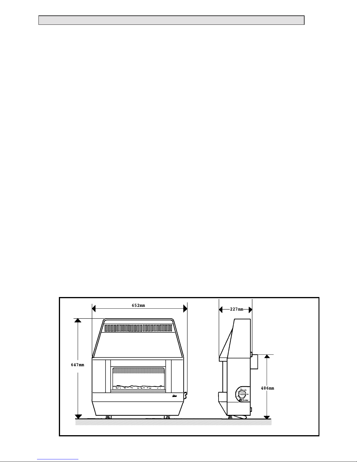
Fig. 1 Overall dimensions

3
1. APPLIANCE D ATA
1.1 This product uses a fuel effect piece containing
Refractory Cer amic Fibres (RCF ), which are man-made
vitreous silicate fibres. Excessive exposure to this
material ma y c a use temporary ir ritation to eyes, skin and
respiratory tract. Consequently, it makes sense to take
care when h andlin g th is article to en su re that the relea se
of dust is kept to a minimum. To ensure that the release
of fibres from this RCF article is kept to a minimum,
during installation and servicing we recommend that you
use a HEPA fi ltered vacu um to remove any dust and
soot accumulated in and around the fire before and after
working on the fire. When replacing this article we
recommend tha t the replaced i tem i s n o t br ok en up, but
is sealed with in a heavy duty polythene bag, c learly
labelled as RCF waste. This is not classified as
“hazardous waste” and may be disposed of at a tipping
site lic ensed for t he disposal of industri al waste.
Protective clothing is not required when handling this
article, but we recommend you follow the normal
hygiene rules of not smoking, eating or drinking in the
work area and always wash your hands before eating or
drinking.
This appliance does not contain any component
manufac tu red from asbestos or asbestos rela ted
products.
1.2 The appliance data badg e i s on the inner f a c e of
the back panel near the bottom l eft corner. There is also
a label giving a serial number and the appliance G.C
number on th e right side of th e ou ter case near the
bottom.
1.3 General Data
The overall dimensions are shown in fig.1.
Gas: Natura l (G20)
Supply pressure: 20mbar (8in. w.g)
Gas consumption at
Control Setting: Gross Heat Input
4 5.77kW (19,700Btu/h)
3 4.16kW (14,200Btu/h)
2 2.40kW ( 8,200Btu/h )
1 1.65kW ( 5,600Btu/h )
Burner type: Duplex
Injectors:- Upper: Bray Ca t 99 Size 150B
Lower: Bray Cat 99 Size 240
Burner test pressure: 17.46 + 0.75mbar
(cold) (7.0 + 0.3in. w. g)
Pilot & atmosph ere: SIT ref. OP 9044
sensing device
Control Tap:- Duplex fou r posi ti on. Fitted
with integr a l piezo-electric
igniter and thermocouple
activated el ec tr o-magnetic
shut-off valve.
Inlet connection: Rp1/4 (1/4”BSP)
Aeration: Non-adjustable
2. GENERAL INSTALLATION REQUIREMENTS
2.1 The installation should comply with the rules in
force.
In your own interest and that of safety, in the United
Kingdom, it is the law that all gas appliances are installed
by competent persons in accordance with the current
edition of the Gas Safety (Installation & Use)
Regulations. Failure to install appliances correctly could
lead to prosecution.
The Counci l of Registered Ga s Installer s (CORGI)
requires its members to work to recognised standards.
The installation must be in accordance with these
instructions.
In the United Kingdom the installation must also be in
accordance with:
a) All the relevant parts of local regulations.
b) The Building Regulations issued by the
Department of th e En vironment or th e Buildin g
Standa rds (Scotland) ( Co nsolidation) Reg ulatio ns issued
by the Scottish Development Department.
c) All relevant codes of practice.
d) The relevant parts of the current editions of the
following British Standards:BS 715
BS 1251
BS 1289 Part 1
BS 1289 Part 2
BS 4543 Part 2
BS 5440 Part 1
BS 5440 Part 2
BS 5871 Part 1
BS 6461 Part 1
BS 6891
In the Republic of Ireland the installation must also
conform with the national and local regulations in force.
2.2 The appliance must not stand on a carpet or any
other combustibl e ma terial.
If a panel h a s to be f i tted to the fireplace opening to meet
the requi red opening si zes shown below, it mu st be
made of non-combustible material.

4
2.3 In the United Kingdom, as supplied, the
appliance can be installed in the following situations.
2.3.1 Conventional fireplace and hearth
The appliance can be installed to a fireplace complete
with surround and hearth
The firepl a c e opening must be with i n the following
dimensions:
Width: Max. 432mm
Min: 305mm
Height Max: 610mm*
Min. 510mm
* Though the total height of the c l osu re plate will
accommodate a ma ximum opening height of 650mm,
heights above 610mm will leave the closure plate and
sealing ta pe vi sible above the appl iance.
The appliance must be mounted on a non-combustible
hearth (N.B. conglomerate marble hearths are
considered as non-combustible). The hearth must be at
least 710mm wide x 300mm d eep. The hearth ma terial
must be at least 12mm thic k. Th e periphery of th e
hearth (or fender) should be at least 50mm above floor
level to discourage the placi n g of carpets or ru gs over it.
The applian c e ca n be fitted to a purpose made
proprietary class “O” 100“C or 150°C surrou nd.
2.3.2. Wall mounted
The appliance can be wall mounted.
The opening must be within the following dimensions:
Width: Max. 432mm
Min. 305mm
Height: Max. 610mm*
Min. 372mm
* Though the total height of the c l osu re plate will
accommodate a ma ximum opening height of 650mm,
heights above 610mm will leave the closure plate and
sealing ta pe vi sible above the appl iance.
The centre of the flue spigot must be at least 512mm
above the finished fl oor covering.
2.3.3. Precast flue
The appliance can be installed to a fireplace that has a
precast concrete or clay flue block system conforming to
BS1289. The appli ance is suit a b l e for insta l lations
conforming to older versi ons of BS1289 as well as the
current edition. The flue blocks must have a minimum
width not less tha n 63mm and a cross-sectional a rea not
less than 13,000mm
2
.
Older ed itions of BS1289 r equired
a cross-sectional a rea of 13,000mm
2
. The current
revision of the standa rd requi res 16,500mm
2
. This
appliance is suitable in both cases.
The chimney should be on or two storeys h igh but not
less than 3m vertical height and be correctly terminated.
No mortar f angs between the bloc k s sh ou ld be extruded
into the flueway. If raking blocks are used, they must be
fitted in accordanc e with the manufacturer’ s
instructions. Mortar must not be allowed to drop down
and accu mulate in th e r aked positions.
The firepl a c e opening must be with i n the following
dimensions:
Width: Max. 423mm
Min: 305mm
Height Max: 610mm*
Min. 610mm*
* Though the total height of the c l osu re plate will
accommodate a ma ximum opening height of 650mm,
heights above 610mm will leave the closure plate and
sealing ta pe vi sible above the appl iance.
2.3.4. Metal flu e box
The appliance can be installed to a metal flue box
complying with th e c onstructiona l requirements of th e
curren t edition of BS715.
The opening must be within the following dimensions:
Width: Max. 432mm
Min: 380mm
Height Max: 610mm*
Min. 510mm
*Although the total height of the closure plate will
accommodate a ma ximum opening height of 650mm,
heights above 610mm will leave the closure plate and
sealing ta pe vi sible above the appl iance.
2.4. Flues
The flu e m ust be clear of any o bst ruction and its base
must be clear of debris.
The flue must be completely sealed so that combustion
products do not c ome i nto contact with combustible
material s ou tsi d e the chimney.
Suitable flues are as follows:(a) 225mm x 225mm conventi onal brick f lue. If a
flue li ner is used, it must be a mini mum of 127mm (5in)
diameter. The liner must be sealed to th e surrounding
area above the fireplace open ing and to the top of the
chimney with an approved terminal being used.
(b) A properly constructed precast flue conforming
to B.S 1289.
(c) A flue pipe with a min imum diameter of
127mm 5in.). See B.S 6461 Part 1 for suitabl e ma terials.
Metal flu e pipes must comply with B.S 715. See section
2.3.4 of thi s ma nual for flue box opening sizes.
2.4.1 The flue must have a minimum equiva lent
height of 3m.
2.4.2. The flue mu st serve only one fireplace.
2.4.3 Any damper or register pla te should be
removed. If removal is not possible without carrying out
structural work, the damper or plate may be left in the
flue provided that it is permanently s ecured in the fully ope n
position.
2.4.4. If the appliance is intended to be installed to a
chimney which was previously used for solid fuel, the
flue must be swept clean prior to installation. All flues
should be inspec te d for sou ndness and freed o m from
blockages.
2.5 If the fir epl ace opening is a n underf loor drau ght
type, it must be sealed to stop any draughts.
2.6. The flue spigot and any spigot extension must
be capable of passing through the closu r e plate by at least
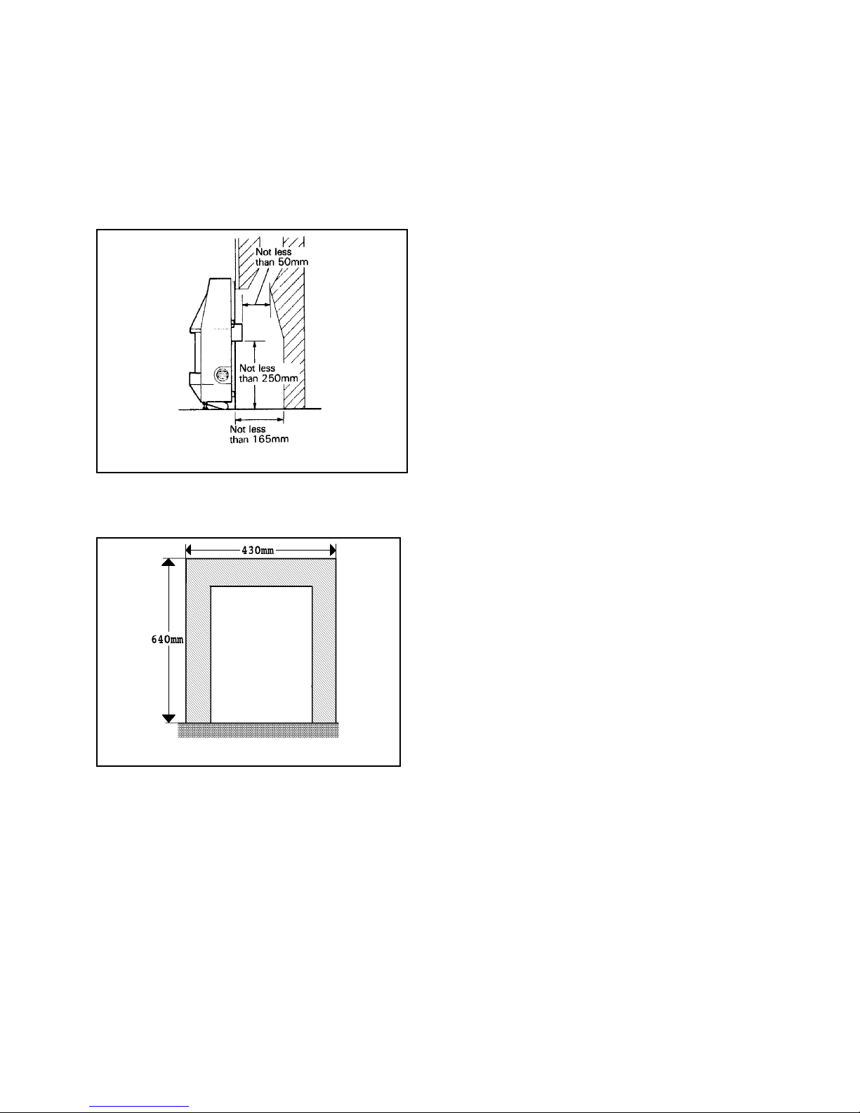
5
25mm with a min i mum clearance of 50mm between its
open end an d the nearest obstr uction.
There must al so be a minimum c learanc e of 165mm
between the back of the closure plate and the bac k of the
catchment spac e.
The catchmen t spa c e below the flue spigot must extend
at least 250mm downwards measured from the bottom
of the flue spi got.
See figure 2.
2.7. If the fire is to be fi tted a gainst walls with
combustible cladding, the cladding must be removed
from the ar ea shown in f ig.3.
2.8. The front of th e fireplace should be fla t over an
area suff icient to ensur e a good seal with the closure
plate. The flat surface shoul d extend for a height eq ual to
that of the closure plate plus 20mm and a for a width
equal to tha t of the closure plate plus 40mm.
2.9. The minimum c learance from the top surface of
the applia nce to the und er side of any sh elf made fr om
wood or other combu sti bl e ma terials is as fol l ows: -
• For a shelf up to 150mm deep
Minimum c learanc e = 150mm
• For a shelf deep er than 150mm
150mm + 12.5mm for ever y 25mm d epth
over 150mm.
2.10. The minimu m allowable d i sta nce to a corner
wall or any other projection at either side of th e
appliance is 100mm.
2.11. The space between the fireplace f ront face and
the back of the outer case must not be filled in.
2.12. Please no te that soft wall coverings (e.g.
embossed vinyl etc .) are easily affected by h eat. They
may, theref or e, scorch or become discoloured wh en
close to a heating appliance. Please bear this in mind
when installing.
2.13. An extra c tor fan may on l y be used in the same
room as this appliance, or in any area from which
ventilation for the appliance is taken, if it does not affect
the safe performance of the appliance. Note the spillage
test requirements detailed further on in this manual. If
the fan is likely to affect the appliance, the appliance
must not be installed unless the fan is permanently
disconnected.
2.14. In the United Kingdom no special ventilation
bricks or vents are required in the room for this
appliance.
In the Republic of Ireland permanent ventilation must
comply with the regulations currently in force.
Fig. 3 Area to be free of combustible cladding
Figure 2 Fireplace catchment space

6
3. UNPACKING & PRE-INSTALLATION PREPARATION
3.1. C arto n Co n t e n t s
The carton contains the following:-
1. Fire assembly.
1. Ceramic fuel effect (In packaging inside
firebox).
1. Closure plate.
1. Flue spigot.
1. Pair of feet (for floor mounting the appliance).*
1. Pair of feet shrouds (for floor mounting th e
appliance).*
1. Pack of fixings containing:
2. Plastic caps for foot screws.
4 No 8 tapping screws for flue spigot
4 Woodscrews for wall mounting
4 Wall plugs
2 Knurled screws for feet shrouds
4 M5 screws for feet
1. Inlet elbow connector.
1. Smoke match tube.
Remove all the items carefully to prevent damage. Some
items may be contained in the packaging fitments Examine the packaging carefully before discarding.
Check that a ll the items are present and undamaged .
*The polystyrene top f itment contai ning the feet a nd
feet shrou ds indic ates which i t ems a re for the left and
right sides. To ease identificatio n at the assemb ly stage,
leave the par ts in the polystyrene until you are read y to
fit them.
3.2. Fireplace Flue Pull
After preparing the fi replace, appl y a lighted match ,
paper or smoke match to the chimney openi ng. Observe
the smoke. If there is a definite flow in to the opening
continue with the instal lation. If th ere is not a defi nite
flow, preh eat the chimney for a few min utes and recheck
If there is still no definite flow, the chimney may need
attention. Do not fit the appliance. Seek expert
advice.
3.3. Appliance Preparation
3.3.1.
Stand the fire upright.
3.3.2. Detach the window surround (See figure 4):
a) Remove the two knurled screws immedia tely
below the outer case canopy.
b) Lift the surround c l ear of the slots in the outer
case apron
3.3.3. Remove the control knob by pulling clear of the
gas tap spindle.
Fig. 4 Window su rrou nd remov al

7
3.3.4. Remove the control bezel by unscrewing two
screws (see fig. 5) .
3.3.5. Detach the outer c a se by r emovi ng the screws at
the case sides (see fig.5) .
3.3.6. Pull the bottom of the case forward s while
springin g th e bottom c orners outwar d s to clear the fixing
brackets. Lift the case upwards and forwards to clear
(see fig.5). P lace caref ully to one sid e.
3.3.7. Remove the window u n it by detachin g th e
knurled screws at the bottom corner s. L ift the window
unit up to clear the top flange of the firebox and pla c e
carefully aside (see fig.6).
3.3.8. Check ignition spark
Before attempting to install, i t i s wor th checking tha t the
piezo electri c spark igni tion system operates
satisfactorily.
To initiate the spark, temporarily refit the control knob
to the tap spind l e. Depress the contr o l k nob and whi l e
keeping it depressed, turn anticlockwise through
approximately 60° to the 1/IGN position. A spa r k sh ould
track fr om th e electrode pin to the thermocoupl e ti p. If
there is no spa rk or incorrect track i ng, check th e spa rk
gap between the electrode wire and thermocoupl e ti p
(see figure 7). If the spark gap is correct, check the
ignition wiring.
Remove the control knob after checkin g.
3.3.9. For floor mounted appliances
3.3.9.1 Fit the shroud s to th e f eet with the knur led
screws supp lied (see fi g ure 8). Sl ide the shr o uds up to
the feet as far as they will go. Tighten the knurled
screws.
Identification of the left and right side components is
shown on the pol ystyrene fitment c ontaining the parts.
Fig. 5 Outer case removal
Fig. 6 Window unit removal
Fig. 7 Pilot spark gap
Fig.8 S hr oud to foot asse mbly (Left side shown)

8
3.3.9.2 Fit the feet to the u n derside of th e a ppliance
feet mountin g brackets (See figu re 9).
3.3.10 Fit th e flue spigot to the back of the fire using
four screws provided.
3.3.11 If the fire is fitted to a recessed fireplac e, an
extension flue spigot up to a maximum total length of
125mm may be used. The extension must be a tight fit
over the flue spi got a n d be secured by two self tappin g
screws. Note th e minimum cl earance r eq uired as sh own
in figure 2.
3.4 Fit The Closure Plate
(Figs 10, 11 & 12)
3.4.1. If a centre gas pipe connection is required cut an
opening at th e bottom of the closure plate. (The gap
between the pipe an d the opening in the closure pl a te
should be sealed with tape after c on nection,)
3.4.2. Hearth mounting (figure 11)
The closur e plate must be fitted a nd sealed to th e hearth
and fireplace opening using a suitable heat resistant
material . If necessar y c ut the closur e plate. Leave th e
closure pl a te suffici ently large to over lap the fir eplace
opening by 25mm. Make sure that the rectangular air
relief openings are fully within the fireplace opening.
3.4.3 Wall mounting (Figure 12)
The closur e plate must be fitted and sealed to th e
fireplace opening using a suitable heat resistant material.
If necessar y cut the closure plate. Lea ve the closure plate
sufficiently large to overlap the fireplace opening by
25mm. Make sure that the rectangular air relief openings
are ful l y wi thin the fi replace openin g.
The underside of the ou ter case must be at l ea st 115mm
above any carpet or other fl oor covering. To achieve this,
the centre of the flue spigot hole will be at least 512mm
above the finished fl oor covering.
3.4.4. Check the flue pull with c l osure plate fi tted by
applying a lighted match or smoke match to the flue
spigot opening in the closure plate and observe the
smoke. If there is a definite flow continue with the
installa ti on. If not check the fitting of th e c l osu re plate.
The fireplace flue pull check described in section 3.2
should have confirmed that the fireplace itself is
satisfactory.
Fig. 9 Foot to bracket assembly (left side shown)
Fig. 10 Closure plate
Fig. 11 Closure plate fixing to hearth
Fig. 12 Closure plate fixing to wall opening

4. APPLIANCE INSTALLATION
4.1 Installin g T o A Heart h
4.1.1.
The levelling screw lock nuts should be
accessible below th e shroud s. If necessa ry, loosen t he
knur led screws sec uring t he shrouds, raise the shrouds
and resecure them. To prevent scratching th e hearth, fit
the two plastic caps (Supplied in the accessory pack)
over the heads of the levelling screws. See figure 13.
4.1.2 Place the fire centrally on the hearth making
sure that the spigot lines up with the spigot hole in the
closure pl a te. Gently slide the applia nce into plac e. The
spigot must enter the closure pl a te to a depth of at least
25mm.
4.1.3 Level the fire by loosening the lock nuts and
turning the levelling screws in the feet up or down as
required while they bear on the hear th. When th e f ire is
level and square to the wall, retighten the lock nuts.
Loosen the kn urled screws securing the feet shrouds and
lower the shrouds until they cover the levelling screws.
4.2 Wall Mountin g
The position of th e wa ll fixi n g h oles in relati on to the
closure pl a t e spi g ot h o l e are shown in fig.14.
4.2.1 Mark the positions of the two upper fi xing holes
using the dimensions as shown in fig. 14. The positions
can alternatively be marked by placing the fire in
position and ma rking the wal l through th e u pper holes
in the back pan el.
4.2.2 Drill and plug the holes. Fit a woodscrew in
one hole. L ea ve about 12mm gap between the screw
head and th e wall to han g th e fire.
4.2.3. Hang the fire on the upper screw making sure
that the fl ue spigot engages thr o u g h the closure pl a t e.
4.2.4. Mark the positions of the bottom fixing holes
through the back panel, ensuring that the fire is level.
4.2.5. Remove the fire. Drill and plug the bottom
fixing holes.
4.2.6. Replace the fi re. Fit three woodscrews, two
through th e bottom h oles and one thr ough the
remaining top hole. Tighten all four woodscrews.
4.3. Gas Supply Connection
4.3.1.
An Rp1/4 (1/4in. B.S.P.) elbow con nector is
provided. Th is can be revolved through 360° to the
connection position required. If a rear centre connection
is required through an opening cut in the closure plate
(see section 3.4. 1.), seal the ga p between the plate an d
the pipe with tape a f ter connection.
4.3.2. Provision for isolation of the gas supply must be
provided u pstream of the appl iance for sa fety and
servicing.
4.3.3. The supply pipe must be of a rigid material (e.g.
copper). A flexible connection must not be made.
4.3.4. Pressure check the installation pipework for gas
soundness in accordance with the current edition of
BS6891.
4.4 Fit Coal And Wind o w
4.4.1.
Place the coal bed in position Make sure that
the coal r ests on the ledges at the sides of the f irebox and
that its back face is touching the back of the firebox..
(see fig.15).
4.4.2. Replace the window unit, making sure its top
channel locates over the top fl a nge of the firebox
opening. Ref i t the two knurled screws and tighten .
Fig. 13 Protectiv e ca ps
Fig. 15 Coal bed loca ti on
Fig. 14 Wall fixing holes

10
5. FULL OPERATING CHECKS
5.1 Check Control Settings
5.1.1.
To help in checking the control positions while
the outer case is detached, pl ace the control bezel over
the gas tap spindl e a nd against th e ta p bracket.
Temporarily secu re to the tap bracket with one of the
screws.
5.1.2. Fit the control knob over the ga s tap spi ndle.
5.1.3. Depress the control kn ob a nd turn
anticlockwise partially towards the 1/IGN position until
some resistance is f elt. Keep dep ressed at this positio n
to purge air from the system then, while keepin g it
depressed, turn fully to the 1/IGN posi ti on. A spark
should be generated at the pilot while turning. The spark
should ignite the pilot.
5.1.4. When pil ot ignition has been achieved, keep the
control knob dep ressed for approxi m a t ely ten seconds to
allow the thermocouple probe to warm up and th en
release it. If the pilot does not remain alight, ensure that
the air h a s been purged, that the pilot orifice is clear and
that the thermocouple connections are sound. Replace
the pilot unit if necessary (see servicing section of this
manual).
5.1.5. Check all the control settings. These a re:-
Knob
Position Burner appearance
1/IGN Centre section on low. Outer
sections off.
2 Centre section fully on. Outer
sections off.
3 Centre section fully on. Outer
sections on low.
4 Centre and outer sections fully on.
5.2. Check Reference Pressure
The appliance is pre-set to give th e c orrect heat input at
the inlet pressure shown in section 1 of this manual. No
adjustm ent is necessary. Chec k t he burner pressur e b y
fitting a pr essu re gauge at the test poin t. The test point is
on the pipe connecting the gas tap to th e l ower injector.
Check the pressu re with the appl iance alight and set a t
maximum output (Control position 4).
After checking, turn off the appliance. Remove the
pressure gauge and replac e t he test point sea ling screw.
Relight the appliance. Turn to the maximum output
position and te st aroun d the sealing screw for gas
soundness with a suitable leak detection fluid.
6. FINAL ASSEMBLY & CHECKS
6.1 Fit The Outer Case
6.1.1.
Detach the con trol knob and control bezel .
6.1.2. Refit the outer c a se. Ma ke su re that the centre
strip at the top back of the case is located beh i nd the
vertical face of the back panel.
The rearwa rd angled ears near the top c o r ners of the
back panel shoul d be behind the outer case top plate,
(see fig.16).
6.1.3. Secure the case at th e bottom si d es wi th the two
screws previously removed.
6.1.4. Place the control bezel bac k in position a nd
secure it to the gas tap br a c ket wi th two screws.
6.1.5. Fit the control knob over the ga s tap spi ndle.
6.1.6. Make sure that th e c oa l is not dislod ged when
refittin g th e c a se.
6.1.7. Refit the window surround using the two
knurled screws previously removed (The reverse
method to that descr ibed in section 3.3.2). Make sure that
the outer edges of the surround sides are inside the outer case.
6.2. Test For Spillage
A spillage test must be made before the installed appliance
is left with the customer.
6.2.1. Close all door s and windows in the room
containing the fire.
6.2.2. Light the appl iance and set th e co n trol knob to
the maximum posi tion (Position 4).
6.2.3. Leave the appliance on f or five minutes.
6.2.4. There are two types of smoke match holders. One
has a copper finish, the other is plain steel. Please apply
the relevant parts of the spillage test instr u ctions
Place the smoke ma tch tube (with l i ghted match) on top
of the wall spa cer bracket at the r ea r right side of th e
appliance.
Copper finish tubes: Slide the tube in until the second
indent is level with the outer edge of the spacer bracket.
A raised ring round the tube (approx. 25mm from the
indent) shoul d be visible along t he casing side (see
fig.17).
Plain steel tubes: Slide the tube until the indent is level
with the edge of the casing si d e (see f ig.17).
Fi
g
.16 Outer case top location
Fig.17 Smok e match tube position

11
The installation is satisfactory if all the smoke is drawn
into rectangular opening in the closure plate. If any
smoke is escapes from the top or side of th e a ppliance,
leave the appliance alight at the maximum setting for a
further ten minutes an d then repeat th e test. If all the
smoke is still not drawn into the closure plate opening,
Disconnect the appliance and seek expert advice.
6.2.5. If the above test is satisfactory, open al l interna l
connecting doors, ha tc hes, etc. in the room. Keep all
doors and wi n dows that open to the outsid e of the
building closed. recheck for spillage as above. If an
extractor fan is installed in the same room as the
appliance or a connecting room, check that spillage does
not occur wi th the fan operating and al l doors and other
openings between the fan an d the applian c e open . If all
the smoke is dra wn into closu r e plate opening, continu e
with the insta l lation. If th e test i s n ot sa ti sf a c tory,
Disconnect the appliance and advise the customer of the
cause of failure.
6.3 Flame Superv is io n & Spillage
Monitoring System
This pilot unit incorporates a system which will
automatica l ly shut off the ga s suppl y if the pilot f l a me
goes out or if there is insufficient oxygen due to spillage
or lack of ven tilation.
Check that th e system operates properly a s f o l lows;
6.3.1 Light the appl iance. Set at positi on 4 and leave
for one minute.
6.3.2 Turn back to “O F F” to extingui sh th e pilot.
Note the time when the pilot goes out. Listen f o r a snap
sound at the gas ta p . Note the time when the sound is
heard. This sound is caused by an electromagnetic valve
shutting of f the gas supply throu gh the tap. The valve is
located in the body of the tap. The valve shou l d operate
within 60 seconds of the pilot going ou t. If the valve does
not operate within this time limit do not allow the
applian c e to be used until th e fault ha s been corrected.
This monitoring system must not be adjusted, bypassed or
put out of oper ation.
This monitoring system, or any of its parts, mu st only be
exchanged using Valor authorised parts.
7FINAL REVIEW
7.1 Make sure that the floor plate has been r efitted.
7.2 Recheck the operation of the f ire at all c ontrol
positions.
7.3. Visually inspect the appliance. Clean off any
marks incurred during installation.
7.4 Advise the cu stomer how to operate the f ire.
7.5 Explain to the customer that th e a ppliance ha s a
flame failure and spillage monitoring system. Point out
the explan ation of this system shown in th e owner’s
guide.
7.6 Advise the customer tha t , if the igniter fails, the
fire can be lit with a match as described in the users
instructions.
7.7 Advise the user that the window will require
cleaning periodically outside and inside as described in
the users instructions. Explain how to remove and
replace the window unit for cleaning the inside of the
glass etc.
7.8 Advise that th e f ire may give off a sl ight odour
while new. This is quite normal and it will disappear
after a shor t period of use.
7.9 Advise that any clean i ng must only be ca rried
out when the fire is off and cold.
7.10 Advise the cu stomer that they should read th eir
Owner’s guide before oper ating the fi re and al wa ys
follow the advice in the section headed “Cleaning your
fire”.
7.11 Recommend that the appliance should be is
serviced and the chi mney inspected by a co mpetent
person at least annually.
7.12 Hand these i nstructions and the own er’s guide
to the customer.

12
8. SERVICING & PARTS RE PL ACEMENT
• Always turn off the gas supply and make sure that the
appliance is cool before commencing any servicing.
• Always test for gas soundness and spillage after
servicing the appliance.
• It is recommended that, at least once a year, the
appliance is disconnected and the catchment space
behind the closure plate checked and cleared of any
debris. The closure plate must be resealed to the wall
after checking.
• This product uses a fuel effect piece containing
Refractory Ceramic Fibres (RCF), which are manmade vitreous silicate fibres. Excessive exposure to this
material may cause temporary irritation to eyes, skin
and respiratory tract. Consequently, it mak es sense to
take care when handling this article to ensure that the
release of dust is kept to a minimum. To ensure that
the release of fibres from this RCF article is kept to a
minimum, during servicing we r ecommend that you
use a HEPA filtered vacuu m to r emove any du st and
soot accumulated in and around the f ir e before and
after working on the fire. When replacing this article
we recommend that the replaced item is not broken up,
but is sealed within a heavy du ty polythene bag, clear ly
labelled as RCF waste. This is not classified as
“hazardous waste” and may be disposed of at a tipping
site licensed for the disposal of industrial waste.
Protective clothing is not requ ir ed w h en ha ndling this
article, but we recommend you f ollow the nor mal
hygiene rules of not smoking, eating or drinking in the
work area and always wash your hands bef ore eating
or drinking.
8.1 To Remove Window Unit
8.1.1.
Detach the window surround by removing the
two knurled screws immediately below the outer case
canopy and lifting the surround clear of the slots in the
outer case apron (See figure 4 in installation section).
8.1.2. Remove the window u n it by detachin g th e
knurled screws at the bottom corner s. L ift the window
unit up to clear the top flange of the firebox and pla c e
carefully aside (See fig.6 in installation section).
8.1.3. Replace in the reverse order .
8.2. To Remove Outer Case (See fig. 5 in
installatio n s ection)
8.2.1.
Remove the control knob by pulling clear of the
gas tap spindle.
8.2.2. Remove the control bezel by unscrewing two
screws.
8.2.3. Detach the outer c a se by r emovi ng the screws at
the case si des.
8.2.4. Pull the bottom of the case forward s while
springin g th e bottom c orners outwar d s to clear the fixing
brackets. Lift the case upwards and forwards to clear.
8.2.5. Replace in the reverse order . When refi tting,
make sure that th e pl a t e a t th e top back of the case is
located behin d th e vertical face of the back panel bu t i n
front of th e two r ea rward an gl ed ears near the top
corners of th e ba c k pa nel. The two rearward poin ti ng
tabs in the top of th e ou ter case rear pla te sh ould locate
against the inner edges of the ears on the bac k pa nel (See
fig.16 in installation section).
8.3. To Remove The Coal
8.3.1
Remove the window unit as described in
section 8. 1
8.3.2. Remove the coal.
8.3.3. Replace in the reverse order. When repl a c ing,
make sur e that the co al rests on t he ledges at sides of th e
firebox an d that its back fa ce i s tou c h i ng the back of the
firebox (see fig.15 in installation section).
8.4. To Remove The Gas Tap
8.4.1 Remove the outer case a s secti on 8.2 above.
8.4.2. Detach the electrode lead from the pilot un i t by
pulling the lead down and away from the electrode
situated a t the centre rear of the burner.
8.4.3. Disconnect the two pipes li nking the upper a n d
lower inj ec tors at the tap end a nd loosen thei r
connections at the injector ends. Swing the pipes clear of
the tap.
8.4.4. Disconnect the in l et pi pe and pilot pipe f rom
the gas tap.
8.4.5. Remove the l oc knut holdi ng the gas tap to the tap
bracket.
8.4.6. Carefully lift the tap clear to allow a c c ess to the
thermocouple connection. Disconnect the
thermocouple from the tap.
8.4.7. Replace in the reverse order .

13
8.5. To Remove The B urne r, Pipes And
Pilot
8.5.1.
Remove the outer case a s secti on 8.2.
8.5.2. Remove the coal as section 8.3.
8.5.3. Detach the gas tap and disconnec t th e
thermocoupl e f rom the tap as section 8. 4.
8.5.4. Remove the screw and sha k eproof wash er fixing
the burner at the righ t side
8.5.5. Remove the wing nut fixing the burner at the
left side.
8.5.6. Slide the bur ner unit complete with pilot pipe
and main burner pipes and pilot un it to the left and
forward clear of the radiant box.
8.5.7. Remove the pipes, injectors or pilot unit if
required.
8.5.8. Replace in the reverse order .
Note: 1. T h e pilot unit must be replaced as a whole assemb ly .
Its individual components are not separately
replaceable.
2. If removed, ensure that the dust cage is cleaned before
refitting and locates squarely onto the pilot unit without
any gaps between the cage edges and the pilot unit.
3. Make sure that the pilot shield is refitted if removed.
4. When refitting the burner make sure that the
shakeproof washer is fitted under the head of the screw
which engages with t he right hand burner bracket .
This washer prevents the end of the screw from catching
the upper inje ct or hexagon.
8.6. To Remove An Injector
8.6.1. Remove the outer case a s secti on 8.2.
8.6.2. Release the pipe compression fitting to th e
upper or lower injector as required. Lock the injector
with a second spa nner to ensure that it does not move.
8.6.3. Loosen the pipe compr ession fitting at the tap
end and move th e pipe clear.
8.6.4. Remove the injector from the burn er.
8.6.5. Replace in the reverse order .
8.7. To Disconnect The Gas Supply Pipe
Access for gas supply disconnection, may be ea sier if the
floor plate is removed.
8.7.1. Remove the outer case a s secti on 8.2.
8.7.2. Detach the pla te by unscrewing two sc rews
securing it to the side feet and pulling clear (see fig.18).
8.7.3. Replace in the reverse order. When ref itting the
floor plate, make sure that the rear tabs locate through
the upper pair of slots in the back pa nel (see fig.18).
8.8. To Remove The Piezo Generator
8.8.1. Remove the gas tap as section 8. 4..
8.8.2. Make sure that th e ta p i s i n the off position .
8.8.3. Remove the circl i p h olding the pi ezo unit to the
tap. Remove the piezo unit.
8.8.4. Replace in the reverse order .
8.9. To Grease The Control Tap
8.9.1. Detach the tap and remove the piezo gen er a tor
as section 8.8 making sure that the tap is in the off
position.
8.9.2. Remove the two scr ews from the head of the tap.
Remove the nitin g head and spi ndle complete with
collar and spring.
8.9.3. Note the position of the slot in the plu g - ma rk
its position on the ta p body.
8.9.4. Remove the plug rotating slightly while pulling.
8.9.5. Clean and grease the plug lightly with a suitable
grease. Do not apply excessive grease. Particularly, make
sure that the gas ports in th e tap are no t restrict ed by
grease.
8.9.6. Push th e plug into the tap bod y a nd position the
slot in line with the mark previously made on the tap
body.
8.9.7. Reassemble the niting head and spindle
complete with coll a r and sprin g ma ki ng sure that the
components ar e c orrectly engaged . Check the opera tion
of the tap.
8.9.8. Refit the piezo gen er ator.
Fig. 18 Floor plate fixing

14
REPLACEMENT PARTS - SHORT LIST
KEY
NO.
DESCRIPTION No. OFF MAKERS PART
No.
A
B
C
D
E
F
G
H
J
K
Injector - Upper - Bray 99 Size 150b
Injector - Bray 99 Size 240
Gas Tap Copreci & Spark Generator
Spark Generator
Pilot Unit
Inlet El b ow
Window Unit
Control Knob
Coal
Dust Cage
1
1
1
1
1
1
1
1
1
1
522109
522809
558799
521069
545949
532519
522209
520799
558809
567619

15
VALOR HEATING
ERDINGTON, BIRMINGHAM B24 9QP
Because our policy is one of constant dev elopment and improvem ent, details may vary s lightly from t hose giv en in this
publication.
© Valor Ltd
 Loading...