

Valor regency 328, favourite 322, firelite 328 Installation & Servicing Instructions Manual
RADIANT / CONVECTOR
GAS FIRES
Favourite
MODEL 322
Firelite
MODEL 328
&
Regency
MODEL 328
THIS APPLIANCE IS FOR USE WITH NATURAL GAS (G20) AT A
SUPPLY PRESSURE OF 20mbar (8 in w.g.)
THIS APPLIANCE IS FOR USE IN THE UNITED KINGDOM (GB) AND
THE REPUBLIC OF IRELAND (IE) ONLY
We trust that these instructions give sufficient details to enable this appliance to be installed and maintained satisfactorily. However if
further information is required, our Valor advice line will be pleased to help.
Ring 0345 626 341 (local call rates apply).
INSTALLATION & SERVICING INSTRUCTIONS
INSTALLER: Please leave these instructions with the owner
600B520/02
April 2000
Valor Folium Format U/down 12/4 5/22/00 9:33 AM Page 1
Safety First.
Valor fires are CE Approved and designed to meet the appropriate British Standards and Safety
Marks.
Quality and Excellence.
At the heart of every Valor fire.
All Valor fires are manufactured to the highest standards of quality and excellence and are
manufactured under a BS EN ISO 9001 quality system accepted by the British Standards Institute.
The Highest Standards
Valor is a member of the Society of British Gas Industries which works to ensure high standards of
safety, quality and performance.
Careful Installation
Valor is a Corgi registered company. All our gas fires must be
installed by a competent Corgi Registered Installer in accordance
with our Installer Guide and should not be fitted directly on to a
carpet or floor of combustible material.
Valor Heating, Erdington, Birmingham B24 9QP
Because our policy is one of constant development and improvement, details may vary slightly from
those given in this publication
© Valor Heating
Because our policy is one of constant development and improvement, details may vary slightly from those given in this publication.
Valor Folium Format U/down 12/4 5/22/00 9:33 AM Page 2
Page
Appliance dimensions................................................................................................................3
INSTALLER SECTION.................................................................................................................4
Appliance data............................................................................................................................4
General installation requirements..............................................................................................4
Unpacking & pre-installation preparation..................................................................................7
Carton contents .........................................................................................................................7
Fireplace flue pull check ...........................................................................................................7
Appliance preparation................................................................................................................7
Closure plate fitting....................................................................................................................8
Appliance installation.................................................................................................................9
Installing to a hearth..................................................................................................................9
Wall mounting............................................................................................................................9
Gas supply connection ..............................................................................................................9
Fitting the radiants.....................................................................................................................9
Full operating checks.................................................................................................................9
Control setting check.................................................................................................................9
Fitting bottom panel & trims ...................................................................................................10
Spillage check..........................................................................................................................10
Fitting dress guard...................................................................................................................11
Final review..............................................................................................................................11
Servicing & parts replacement ................................................................................................11
Replacing radiants ...................................................................................................................12
Access to burner, pilot, tap, etc...............................................................................................12
Replacing pilot.........................................................................................................................12
Removing burner, tap & pilot..................................................................................................12
Replacing gas tap or injectors.................................................................................................12
Replacing piezo generator .......................................................................................................12
Greasing gas tap......................................................................................................................13
Removing complete fire...........................................................................................................13
Spares short list.......................................................................................................................13
LIST OF CONTENTS
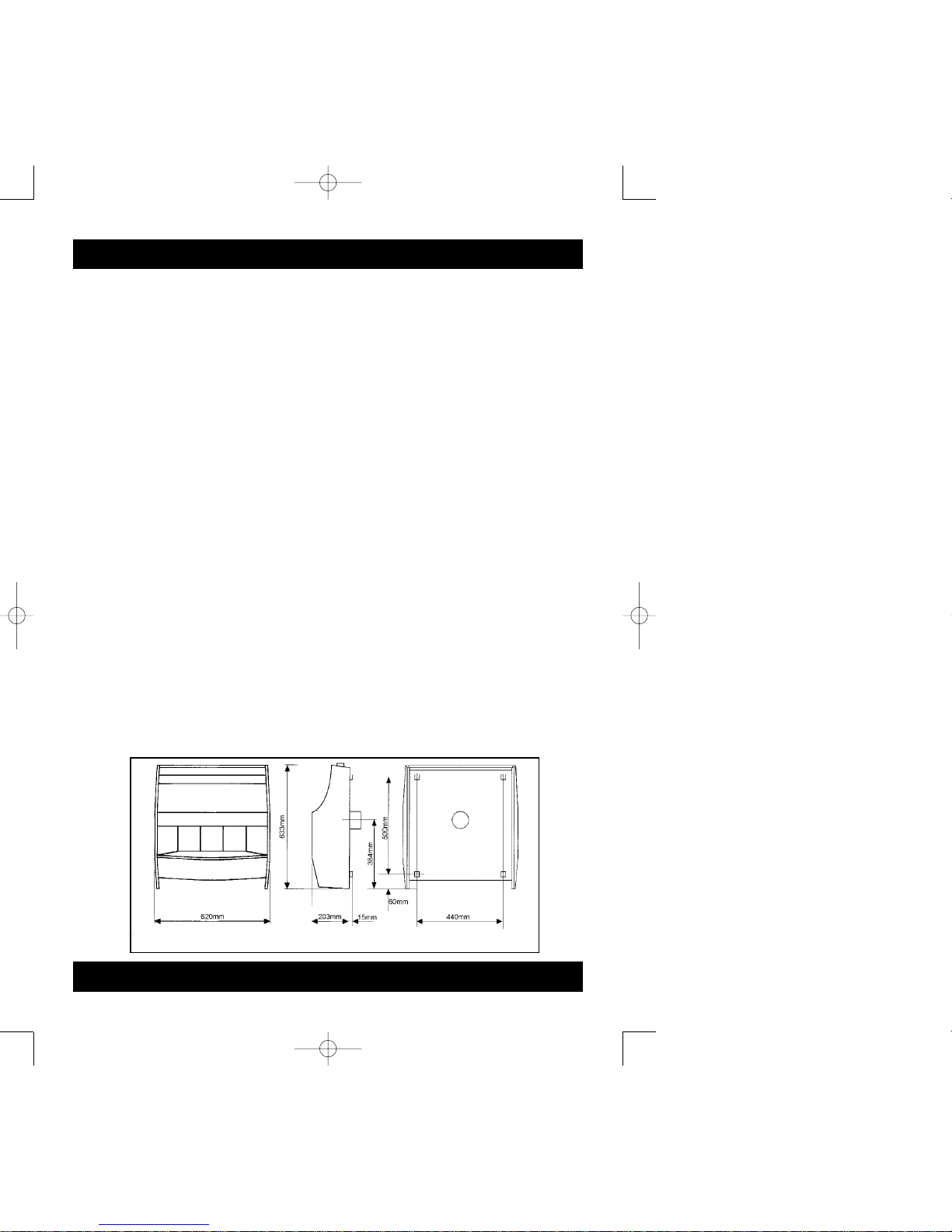
Page 3
Figure 1. Appliance Dimensions
Valor Folium Format U/down 12/4 5/22/00 9:33 AM Page 3

This appliance does not contain any component
manufactured from asbestos or asbestos related
products.
The appliance data label is on the inner face of the
back panel at the lower left hand side. It is visible
when the outer case is removed.
Gas: Natural (G20)
Inlet pressure: 20mbar (8in. w.g.)
Input - Max: 5.28kW (18,000Btu/h)
(Gross) Min: 1.25kW (4,300Btu/h)
Output - Max: 3.2kW (10,900Btu/h)
Min: 0.56kW (1,900Btu/h)
Burner injectors:
Upper (Centre radiant) Bray cat 28 size 120
Lower (Outer radiants) Bray cat 28 size 250B
Burner test pressure
(cold): 18.3mbar (7.2in w.g.)
Inlet pipe connection: Rp1/4 (1/4” BSP)
Pilot & Atmosphere
sensing device SIT ref. OP9044
Ignition: Piezo electric
Integral with gas tap
Aeration: Non-adjustable.
2.1 For the user’s protection, in the United
Kingdom it is the law that all gas appliances
are installed by competent persons in
accordance with the current edition of the Gas
Safety (Installation and Use) Regulations.
Failure to install the appliance correctly could
lead to prosecution. The Council for the
Registration of Gas Installers (CORGI)
requires its members to work to recognised
standards.
In the United Kingdom the installation must
also be in accordance with:
A. These instructions.
B. All the relevant parts of local regulations.
C. The current edition of the Building Regulations
issued by the Department of the Environment
and the Welsh Office or the Building
Standards (Scotland) Regulations issued by
the Scottish Development Department.
D. All relevant codes of practice.
E. The relevant parts of the current editions of the
following British Standards:-
BS 715 BS 1251
BS 1289 Part 1 BS 1289 Part 2
BS 4543 Part 2 BS 5440 Part 1
BS 5440 Part 2 BS 5871 Part 1
BS 6461 Part 1 BS 6891
In the Republic of Ireland the installation must also conform with
the relevant parts of:
a) The current editions of:-
IS 813
ICP3
b) All relevant national and local rules in force.
2.2 The appliance must not stand on a carpet or
any other combustible material.
If a panel has to be fitted to the fireplace opening to meet the
required opening sizes shown in these instructions it must be
made of non-combustible material.
2.3 The appliance can be installed in the
following situations.
Page 4
1.APPLIANCE DATA
INSTALLATION & SERVICING INSTRUCTIONS
2. GENERAL INSTALLATION
REQUIREMENTS
Valor Folium Format U/down 12/4 5/22/00 9:33 AM Page 4

2.3.1 Conventional fireplace and hearth
The appliance can be installed to a fireplace
complete with surround and hearth.
The fireplace opening must be within the following dimensions:
Width: Max. 457mm
Min: 305mm
Height Max: 610mm*
Min. 510mm
* Though the total height of the closure plate
will accommodate a maximum opening
height of 650mm, heights above 610mm
will leave the closure plate and sealing tape
visible above the appliance.
The appliance must be mounted on a non-combustible hearth
(N.B. conglomerate marble hearths are considered as noncombustible). The hearth must be at least 880mm wide x 300mm
deep. The hearth material must be at least 12mm thick. The
periphery of the hearth (or fender) should be at least 50mm above
floor level to discourage the placing of carpets or rugs over it.
The appliance can be fitted to a purpose
made proprietary class “O” - 100“C or O”150°C surround.
2.3.2. Wall mounted
The appliance can be wall mounted.
The appliance is not suitable for installation
on combustible walls.
The opening must be within the following
dimensions:
Width: Max. 356mm
Min. 305mm
Height: Max. 610mm*
Min. 376mm
* Though the total height of the closure plate
will accommodate a maximum opening
height of 650mm, heights above 610mm
will leave the closure plate and sealing tape
visible above the appliance.
The bottom of the fire must be at least
102mm above the finished floor
covering. This requires that the top of the
opening must be at least 612mm above the
finished floor covering.
2.3.3. Precast flue
The appliance can be installed to a fireplace
that has a precast concrete or clay flue block
system conforming to BS1289. The
appliance is suitable for installations
conforming to older versions of BS1289 as
well as the current edition. The flue blocks
must have a minimum width not less than
63mm and a cross-sectional area not less
than 13,000mm
2
. Older editions of BS1289
required a cross-sectional area of
13,000mm
2
. The current revision of the
standard requires 16,500mm
2
. This
appliance is suitable in both cases.
The chimney should be one or two storeys
high but not less than 3m
vertical height and be correctly terminated.
No mortar fangs between the blocks should
be extruded into the flueway. If raking blocks
are used, they must be fitted in accordance
with the manufacturer’s instructions. Mortar
must not be allowed to drop down and
accumulate in the raked positions.
The fireplace opening must be within the
following dimensions:
Width: Max. 457mm
Min: 305mm
Height Max: 610mm*
Min. 610mm*
2.3.4. Metal flue box
The appliance can be installed to a metal flue
box complying with the
constructional requirements of the current
edition of BS715.
The opening must be within the following
dimensions:
Width: Max. 457mm
Min: 380mm
Height Max: 610mm*
Min. 510mm
*Though the total height of the closure plate
will accommodate a maximum opening
height of 650mm, heights above 610mm
will leave the closure plate and sealing tape
visible above the appliance.
2.4. Flues
Suitable flues are:
a) 225mm x 225mm conventional brick
flue. If a liner is used, it must be a minimum
of 127mm (5in.) diameter. The liner must be
sealed to the surrounding area above the
fireplace opening and to the top of the
chimney and have an approved terminal.
b) A properly constructed precast flue
conforming to BS1289 (See
section.2.2.3.)
Page 5
INSTALLATION & SERVICING INSTRUCTIONS
Valor Folium Format U/down 12/4 5/22/00 9:33 AM Page 5
c) A flue pipe with a minimum diameter of
127mm (5in.). See BS6461 Part 1 for
suitable materials.
Metal flue pipes must comply with
BS715. See section 2.2.4. for metal flue box
requirements.
2.4.1. The flue must have a minimum equivalent
height of 3m.
2.4.2. The flue must serve only one fireplace.
2.4.3. Any damper or register plate should be
removed. If removal is not possible without
carrying out structural work, the damper or
plate may be left in the flue provided that it
is permanently secured in the fully open
position
2.4.4. If the appliance is intended to be installed to
a chimney which was
previously used for solid fuel, the flue must
be swept clean prior to
installation. All flues should be inspected for
soundness and freedom from blockages.
2.5 If the fireplace opening is an underfloor
draught type, it must be sealed to stop any
draughts.
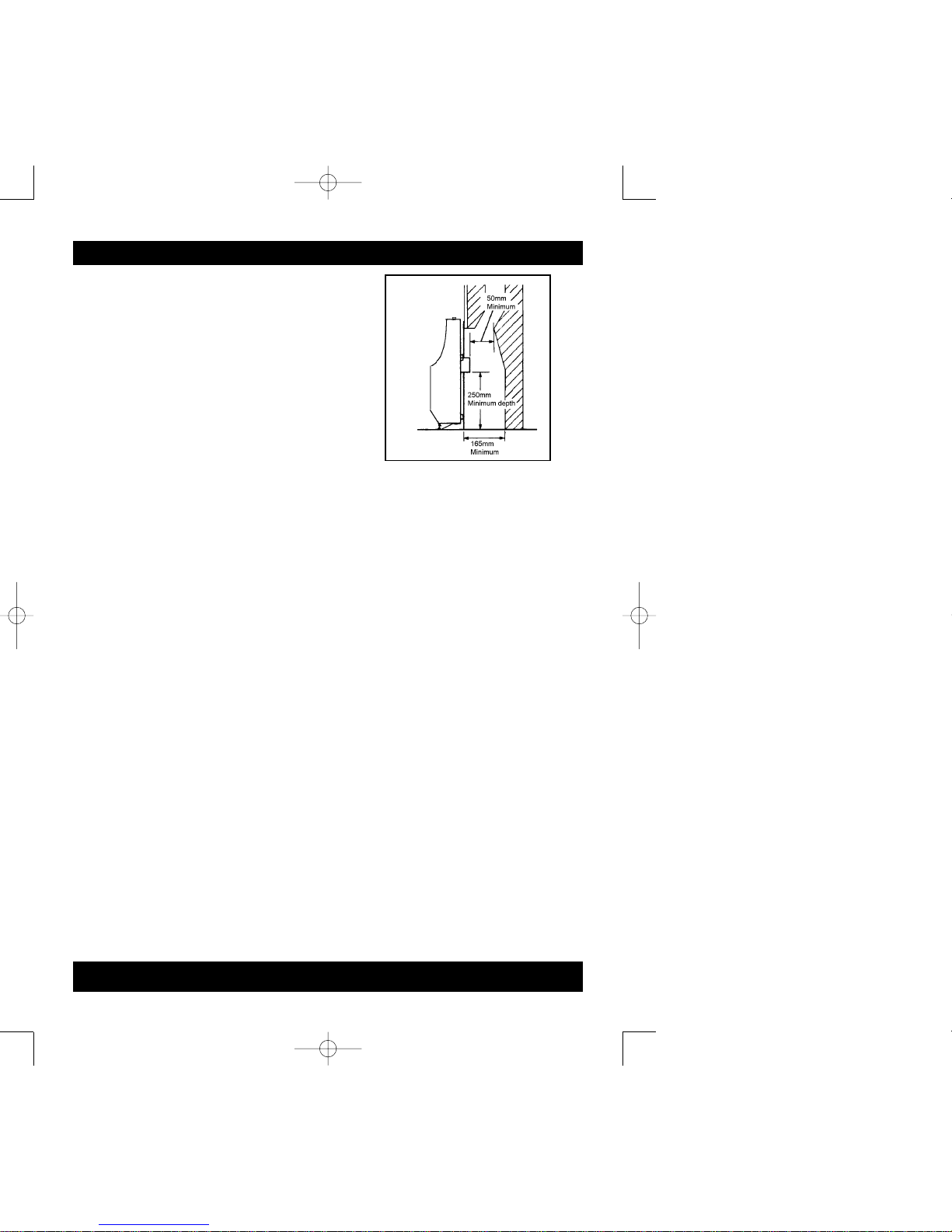
2.6. The flue spigot and any spigot extension
must be capable of passing through the
closure plate by at least 25mm with a
minimum clearance of 50mm between its
open end and the nearest obstruction.
There must be a minimum clearance of
165mm between the back of the
closure plate and the back of the catchment
space.
The catchment space below the flue spigot
must extend at least 250mm downwards
measured from the bottom of the flue
spigot.
See figure 2.
2.7. The front face of the fireplace should be
reasonably flat to ensure that a good seal
can be made with the closure plate.
2.8. The minimum clearance from the top
surface of the appliance to the
underside of any shelf made from wood or
other combustible materials is as follows:-
• For a shelf up to 150mm deep
Minimum height = 203mm
• For a shelf deeper than 150mm
203mm + 12.5mm for every 25mm
depth over 150mm.
2.9. The minimum allowable distance to a corner
wall or other projection at either side of the
appliance is 100mm.
2.10 The space between the back of the outer
case and the front face of the
fireplace must not be filled in.
2.11. Note that soft wall coverings (e.g. embossed
vinyl, etc.) are easily affected by heat. They
may scorch or become discoloured when
close to a heating appliance. Please bear
this in mind when installing.
2.12. An extractor fan may only be used in the
same room as this appliance, or in any area
from which ventilation for the appliance is
taken, if it does not affect the safe
performance of the appliance. Note the
spillage test
requirements detailed further on in this
manual. If the fan is likely to affect the
appliance, the appliance must not be
installed unless the fan is
permanently disconnected.
2.13. No special ventilation bricks or vents are
required in the room for this
appliance.
Page 6
figure 2
INSTALLATION & SERVICING INSTRUCTIONS
Valor Folium Format U/down 12/4 5/22/00 9:33 AM Page 6
 Loading...