


DREAM
DIMENSION
PETRUS
DIMENSION
DIMENSION ELECTRIC RANGE
The product complies with the European Safety Standards EN60335-2-30 and the European Standard Electromagnetic Compatibility (EMC)
EN55014, EN60555-2 and EN60555-3. These cover the essential requirements of EEC Directives 2006/95/EC and 2006/108/EC
08/52282/0 (UK) Issue 2
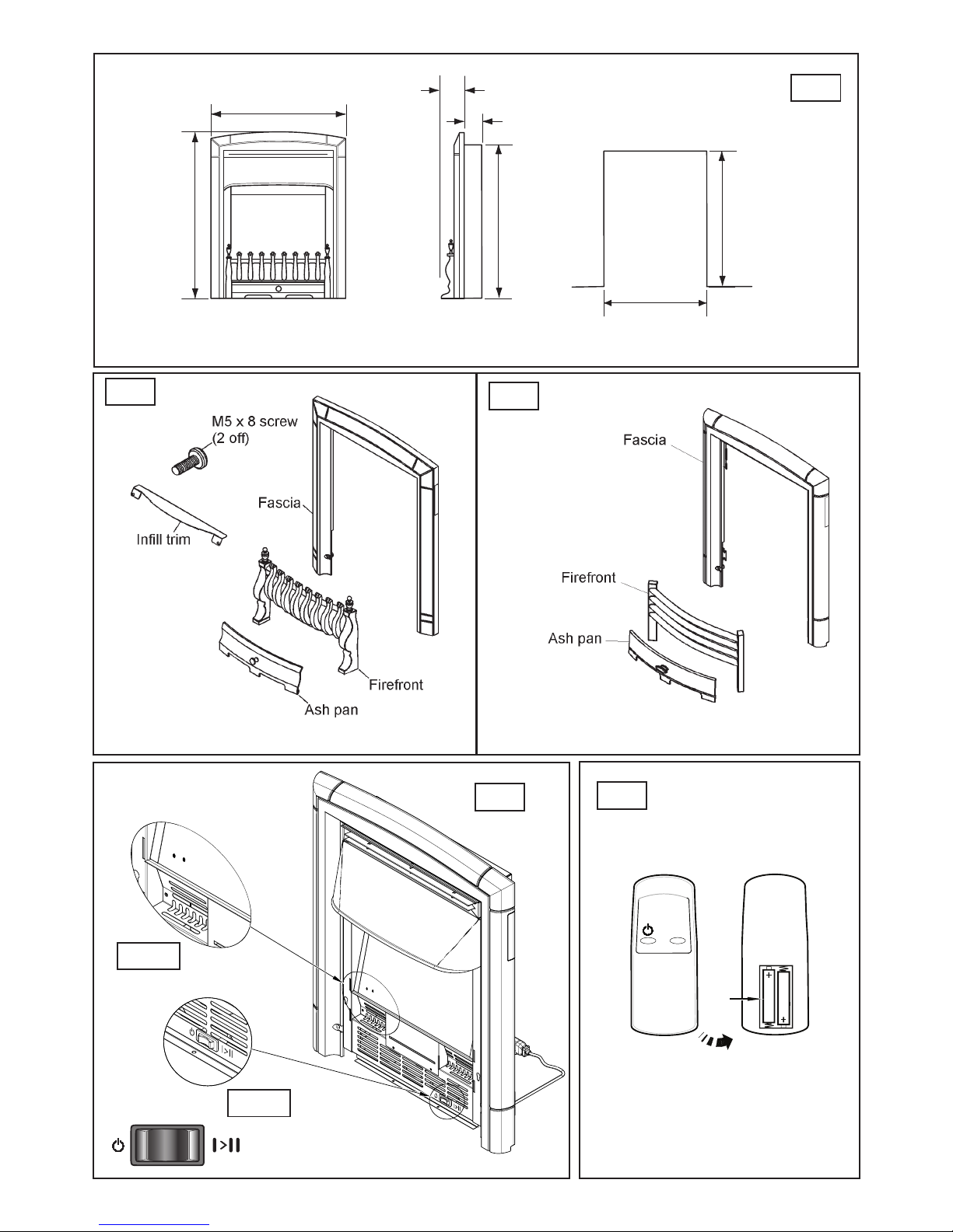
Dream Fascia Pack Petrus Fascia Pack
Fig.1
Fig.2
Fig.3
Fig.5
I
II
Fig.4-B
Fig.4-A
Fig.4
636mm
518mm
90mm (Dream)
92mm (Petrus)
70mm (Without optional spacer frame)
80mm (With optional spacer frame)
563mm
565mm
375mm
Recommended opening dimensions.
IMPORTANT: THESE INSTRUCTIONS SHOULD BE READ CAREFULLY AND RETAINED FOR FUTURE REFERENCE
General
Unpack the heater carefully and retain the packaging for possible future
use, in the event of moving or returning the re to your supplier.
The re incorporates a ame effect, which can be used with or without
heating, so that the comforting effect may be enjoyed at any time of
the year. Using the ame effect on its own only requires little electricity.
A choice of 650W or 1.3kW heat output is provided by the fan heater,
which is located at the bottom of the unit.
Before connecting the heater check that the supply voltage is the same
as that stated on the heater.
Please note: Used in an environment where background noise is
very low, it may be possible to hear a sound which is related to the
operation of the ame effect. This is normal and should not be a
cause for concern.
Electrical connection
WARNING – THIS APPLIANCE MUST BE EARTHED.
This heater must be used on an AC ~ supply only and the voltage marked
on the heater must correspond to the supply voltage.
Before switching on, please read the safety warnings and operating
instructions.
Controls - see Fig.4-A
There is only one switch used to operate any of the controls within the
appliance.
Setting Operation Indication
Flame Effect Press the button once Flame panel illuminated
Flame Effect & half heat Press the ‘I’ button again 1 RED LED
Flame Effect & full heat Press the ‘II’ button again 2 RED LED’s
To turn off any of the Press the button once.
settings
LED indicators - see Fig. 4-B
The TWO LED’s as shown in Fig. 4-B indicates the heat setting and will
illuminate for a couple of seconds every time the heat setting is changed
One LED means Half Heat - 650watts, TWO LED’s means Full Heat 1300watts
- DREAM DIMENSION
- PETRUS DIMENSION
UK
Important Safety Advice
When using electrical appliances, basic
precautions should be followed to reduce
the risk of re, electric shock, and injury to
persons, including the following:
If the appliance is damaged, check
immediately with the supplier before
installation and operation.
Do not use this appliance in the immediate
surroundings of a bath, shower or swimming
pool.
Do not use outdoors.
This appliance must not be located
immediately above or below a xed socket
outlet or connection box.
WARNING : The appliance carries the
Warning Symbol indicating that it must
not be covered or has a Do not cover
label. Do not cover or obstruct in any way
the heat outlet grille located at the top of
the appliance overheating will result if
the appliance is accidentally covered. Do not
place material or garments on the appliance,
or obstruct the air circulation a round the
appliance, for instance by curtains or furniture,
as this could cause overheating and a re risk.
In the event of a fault unplug the heater.
Unplug the appliance when not required for
long periods.The supply cord must be placed
on the right hand side of the heater away from
the heat outlet underneath the appliance.
Although this appliance complies with safety
standards, we do not recommend its use on
deep pile carpets or on long hair type of rugs.
This appliance can be used by children aged
from 8 years and above and persons with
reduced physical, sensory or mental
capabilities or lack of experinence and
knowledge if they have been given supervision
or instruction concerning use of the appliance
in a safe way and understand the hazards
involved. Children shall not play with the
appliance. Cleaning and user maintaince shall
not be made by children without supervision.
Children of less than 3 years should be kept
away unless continuously supervised.
Children aged from 3 years and less than 8
years shall only switch on/off the appliance
provided that it has been placed or installed
in its intended normal operating position and
they have been given supervision or
instruction concerning use of the appliance
in a safe way and understanding the hazards
involved. Children aged from 3 years and less
than 8 years shall not plug in, regulate and
clean the appliance or perform user
maintaince.
The appliance must be positioned so that the
plug is accessible.
If the supply cord is damaged it must be
replaced by the manufacturer or service agent
or similarly qualied person in order to avoid
a hazard.
CAUTION: In order to avoid a hazard due to
inadvertent resetting of the thermal cut-out,
this appliance must not be supplied through an
external switching device, such as a timer, or
connected to a circuit that is regularly switched
on and off by the utility.
This appliance is not equipped with a device
to control the room. Do not use this heater
in small rooms when they are occupied by
persons not capable of leaving the room on
their own, unless constant supervision is
provided.
CAUTION - Some parts of this product can
become very hot and cause burns. Particular
attention has to be given where children and
vulnerable people are present.
These instruction can be found at
www.valor.co.uk

Fig.7
Fig.8
Fig.9
Fig.8a
Fig.10
Fig.6

IMPORTANT: THESE INSTRUCTIONS SHOULD BE READ CAREFULLY AND RETAINED FOR FUTURE REFERENCE
UK
Remote Control - see Fig. 5
The maximum range of use is ~ 15metres.
The buttons on the remote control have the same function as the swiches
on the heater.
For details on the function please refer to the ‘Controls’ section above.
Warning: It takes time for the receiver to respond to the transmitter.
Do not press the buttons more than once within two seconds for correct
operation.
Battery Information - see Fig. 5
1. Slide open the battery cover on the back of the remote control
2. Install AAA batteries into the remote control
3. Replace the battery cover.
Discard Leaking Batteries
Dispose of batteries in the proper manner according to provincial and
local regulations.
Any battery may leak electrolyte if mixed with a different battery type, if
inserted incorrectly; if all the batteries are not replaced at the same time;
if disposed of in a re, or if an attempt is made to charge a battery not
intended to be recharged.
Thermal Safety Cut-out
The built-in overheat cut-out switches off the appliance automatically in
the event of a fault. If this occurs, switch off the appliance or disconnect
the mains plug from the socket. Remove any obstructions which may
have caused the overheating. After a short cooling down phase, the
appliance is ready for use again. If the fault should occur again, unplug
the appliance and contact your local dealer.
Installation
WARNING – ALWAYS ENSURE THE APPLIANCE IS DISCONNECTED
FROM THE POWER SUPPLY BEFORE INSTALLING.
IF THE APPLIANCE HAS BEEN INSTALLED INTO AN EXISTING
FIREPLACE, IT IS RECOMMENDED THAT YOU HAVE YOUR
CHIMNEY CLEANED BY A COMPETENT CHIMNEY SWEEP
AND BLOCK OFF THE CHIMNEY FLUE. THIS PROCEDURE IS
IMPORTANT FOR THE EFFICIENT OPERATION OF THE APPLIANCE
AND WILL ALSO REDUCE HEAT LOSS UP THE CHIMNEY.
The appliance must be secured into position to prevent it from being
tipped over. There are a number of methods to x the appliance in place,
• Method A - Securing the appliance with Screws
• Method B - Securing the appliance with Wire ( Nylon Cable )
• Method C - Securing the appliance with Optional Space Frame
See back page of these instruction for table of pack contents
NOTE: Details of fascia pack contents are shown on Fig.2 and Fig.3
The appliance can be tted into replaces or surrounds where the
following dimension are available
• Width 395mm - 450mm
• Height 565mm - 590mm
• Depth At least 70mm
Method A - Securing with Screws. - See Fig.6
Note- If xing to marble, it is recommend that Method B - Securing
with Wire is used.
Place the appliance into the replace or surround opening, ensure
the appliance is positioned in the middle of the opening. There are
four holes in the side anges - see Fig.6 . Mark through the holes
so that their position is clear when the appliance is removed. With
the appliance removed, drill an appropriate size hole in each of the
marked positions for the wall plug supplied. Insert the wall plugs,
reposition the appliance aligning the holes with the wall plugs. Using
the wood screws supplied secure the appliance in position.
Method B - Securing with Wire - See Fig.7 & Fig.8
Note- This method of securing is recommended when the wall /
brickwork is in poor condition or when a marble back panel / surround
is used.
The xing kit supplied with the appliance includes a nylon wire and
eyescrew, these can be used to secure the appliance in place. Mark
a hole in the centre of the back of the replace approximately 560-
570mm - see Fig.7. Drill an appropriate size hole in the marked
position, insert a wall plug , then screw the eyescrew into the wall
plug. Re-position the appliance infront of the opening, but do not inset
into the opening. On the edge of the side anges there are two small
holes either side the appliance. Thread about 100mm of wire into the
outside small hole on the right hand side ange of the appliance - see
Fig.8 - step 1. Thread the other end of the wire throught the remaining
small hole to the left. Continue to push the wire throught this hole until
there is a small loop of wire on the front of the appliance, bring the
end of the 100mm piece over the top of the side and thread it through
the small loop, pull the long end tight to close the loop, feed the short
piece along the front back through the large hole just below the two
small holes just used.. - see Fig.8a.
Next. thread the long piece of nylon wire throught the eyescrew in
the back of the replace opening. From the back of the appliance,
thread the long piece of wire through the inner small hole on the left
hand side ange - see Fig.8 - step 3. Locate the appliance in the re
place opening , then from the front of the appliance gently pull the
wire on the left hand side to gather up the excess until the appliance
is secured. Thread the remaining wire through the small outer hole,
again bring this wire over the top of the side and thread it through the
small loop and keep tighthening the wire in place until all the excess
wire is used up. Trim the excess to within 100mm and push the
remainder through the larger hole just below the two holes just used. see Fig.8 - step 4.
Method C - Securing with optional space frame - see Fig.9
& Fig.1
Note- The spacer frame enables the appliance to be at wall xed.
For your satefty the frame and the appliance must be securely xed to
the rear wall / surround.
Fitting the spacer frame:
The rear of the spacer frame has wider anges which have key hole
slots. Position the rear of the spacer frame against the wall. Ensure
that the spacer is central to the replace, it is important that the legs
are positioned correctly and are upright. Mark the upper position of the
key hole slots on the wall - see Fig.9 . Remove the spacer frame and
drill a hole on the marked locations using a suitable sized masonry
drill bit for the supplied wall plugs. Insert two wall plugs into the holes,
then screw in two wood screws in to the wall plugs until approximately
6mm of screw is left protruding from the wall.
Fitting the spacer frame to the appliance:
The spacer frame is secured to the appliance in four position - see
Fig.10 . Secure the spacer frame to the appliance using the four No.8
x 3/8 screws supplied.
Fitting the appliance with spacer frame:
Carefully lift the appliance and locate the slots on the rear of the
spacer frame onto the screws in the wall. The screws can be adjusted
to ensure a tight t. When mounting to decorative surfaces such as
wallpaper, care must be taken not to drag the appliance down the wall
as it may damage the decorative surface.
- DREAM DIMENSION
- PETRUS DIMENSION
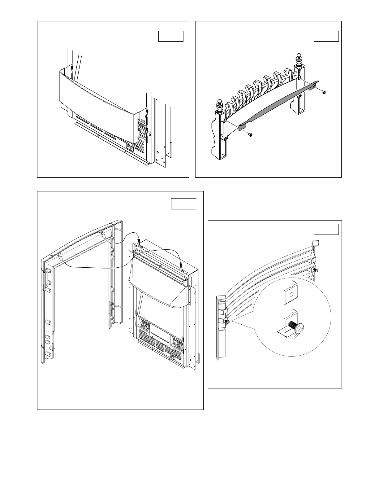
Fig.12
Fig.13
Fig.14
Fig.11
12mm

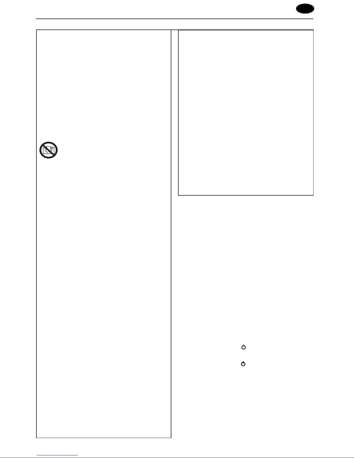
Fitting the Decorative Fascia to the Appliance
Fitting the plastic inll trim ( Petrus Model Only).
Remove the plastic inll trim from its packaging. Locate the four tabs
on the rear of the plastic inll trim into the four slotted holes on the
front of the appliance - see Fig.11 .
Fitting the metal inll trim ( Dream Model Only).
Remove the metal inll from its packaging. Locate the metal inll trim
on the back of the Fret - see Fig.12 . Secure the metal inll trim in
place using the two M5 x 8 screws supplied.
Fitting the fascia.
Remove the fascia from its packaging. Holding the fascia rmly with
both hands , lift into place. Locate the fascia hanging brackets into
the slots on top of the appliance - see Fig.13 . Lower the fascia into
the place and swing the bottom of the fascia towards the appliance.
Secure the fascia in place by the holes in the lower side legs of the
fascia using the two washers and two M4 x 25mm screws supplied.
Fitting the fret and ash pan ( Petrus Model Only).
Remove the fret from its packaging. On the rear of the fret it maybe
tted with hanging screws or they may be supplied in the fret
packaging. Where they are not already tted insert them into the lower
holes on both sides of the fret - see Fig.14. The distance between the
fret and the underside of the screw heads should be approximately
12mm. The screws can be adjusted to obtain the required t. Hang
the fret on the hole slots on the front of the appliance. Position the ash
pan beneath the fret.
Fitting the fret and ash pan ( Dream Model Only).
Remove the fret from its packaging. Locate the fret in front of the
appliance. Position the ash pan beneath the fret.
Maintenance
WARNING: ALWAYS DISCONNECT FROM THE POWER SUPPLY
BEFORE ATTEMPTING ANY MAINTENANCE.
Cleaning
WARNING – ALWAYS DISCONNECT FROM THE POWER SUPPLY
BEFORE CLEANING THE HEATER.
For general cleaning use a soft clean duster – never use abrasive
cleaners. The glass viewing screen should be cleaned carefully with a soft
cloth. There is a mirror located underneath the canopy, this may require
cleaning to ensure a sharp clear image as shown below in Fig.15.
DO NOT use proprietary glass cleaners.
To remove any accumulation of dust or uff the soft brush attachment of
a vacuum cleaner should occasionally be used to clean the outlet grille
of the fan heater.
IMPORTANT: THESE INSTRUCTIONS SHOULD BE READ CAREFULLY AND RETAINED FOR FUTURE REFERENCE
UK
Recycling
For electrical products sold within the European Community.
At the end of the electrical products useful life it should not be
disposed of with household waste. Please recycle where facilities
exist. Check with your Local Authority or retailer for recycling
advice in your country.
After Sales Service
Your product is guaranteed for one year from the date of purchase.
Within this period, we undertake to repair or exchange this product free
of charge (excluding lamps & subject to availability) provided it has been
installed and operated in accordance with these instructions.
Your rights under this guarantee are additional to your statutory rights,
which in turn are not affected by this guarantee.
Should you require after sales information or assistance with this product
please go to www.valor.co.uk where you will nd our self help guide or
ring our helpdesk on 0844 879 3588 (UK) or 01 842 4833 (R.O.I.) .
Spare parts are available from the help desk.
www.valor.co.uk
Please retain your receipt as proof of purchase.
Fig.15
- DREAM DIMENSION
- PETRUS DIMENSION

Valor
Millbrook House
GrangeDrive
HedgeEnd
Southampton
Hampshire.SO30 2DF
TEL: 0844 879 3588
FAX: 0844 879 3583
WEBSITE: www.valor.co.uk
Republic of Ireland Tel. 01 8424833
[c] GDC Group Ltd,
All rights reserved. Material contained in this publication may not be reproduced in whole or in part, without prior permission in writing of Valor, a division of
GDC Group Ltd.
Table of Pack Contents
UK
- DREAM DIMENSION
- PETRUS DIMENSION
Contents Qty. (Not to scale)
Heater
1
No.8 x 3/8
pan head screw
5
Tension wire 1
Screw eye 1
Wood screw 5
Wall plug 5
Contents Qty. (Not to scale)
‘AAA’ Battery 2
Remote 1
M4 x 25mm screw 2
Washer 2
Mains cable 1
Infill trim
(Petrus model
only)
1
I
II
 Loading...