

Page 1
USER MANUAL
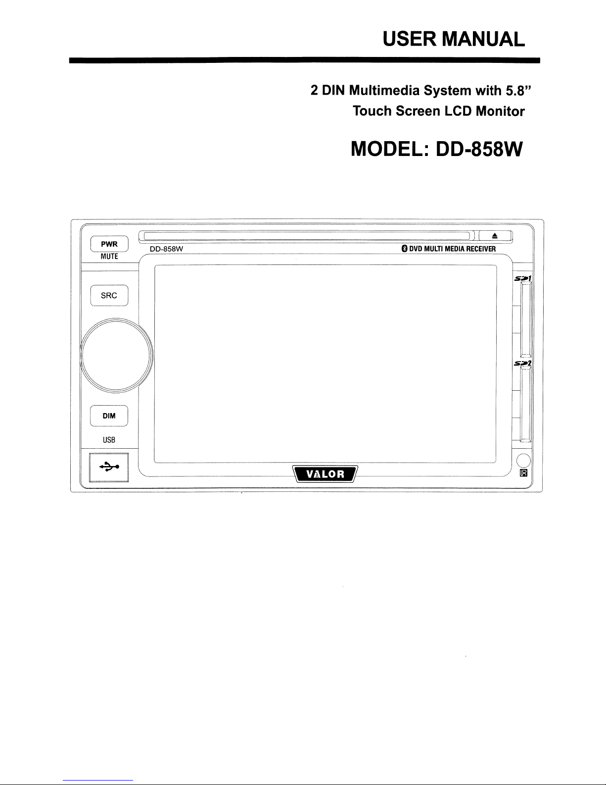
2 DIN Multimedia System with 5.8"
Touch Screen LCD Monitor
MODEL: DD-858W
(
PWR
l .
MUTE
USB
EJ
(I
J
l:::::'===============~==~~~
DD-858W
V/1LOR
0
DVD
MULTI
MEDIA
)) [
~
RECEIVER
o
I!il
Page 2
Congratulation
on
your purchase
DD-858W Car Multimedia Player.
of
this high quality
Before installing or using
ensure current operation. Keep the manual at hand
this
unit, please read
this
Contents
Features
Installation ·········3
Wire Connection
Main Unit Display 9
Remote Control · · · ·..·..·..· ·..· ·10
General Operation
Main Setup 13
Radio Operat.ion 17
····
·..·
··
..
· ·
manual carfully
for
future reference.
··
..
···3
7
11
to
RBDS Operation
CD
Player Operation
MP3/
DVD
DVD
VCD
JPEG
USB/
Bluetooth Operation 35
Media Operation 38
Troubleshooting
Specifications
WMA
Player Operation
Setup
Player Operation 32
Operation 33
SO Card Operation 34
Player Operation
..··..
· ·
19
20
·23
24
27
40
41
Page 3
- 5.8 inch Analog TFT Screen
- Touch Screen Control
-AM/FM
- DVD R/RW, CD R/RW, VCD title playable
- MP3, WMA, MPEG AudioNideo file playable
- Rear Zone Audio Output
- OSD : On Screen Display
- AUX, REAR
VI
EW(Reverse Camera) Input for System Expansion
- USB, SD CARD Input
- High Power MOSFET Devices Output
- Bluetooth Connection compatible (option)
- Media playable (option)
It's a good idea to read all instructions before installation. We recommend having
an
your DD-858W installed by
authorized installer or reputable installation center.
Equipment needed for installing the unit
- Wire cutters and strippers
- Tools to remove existing radio (screwdriver, socket wrench set, etc.)
- Electrical tape
- Crimping tools
- Multimeter
- 18 gauge wire for power connections
- 12 - 18 gauge speaker wire
Precaution
Disconnecting the Battery
To
prevent a short circuit,
(-) battery cable prior to installation.
NOTE: If the unit is to
navigation computer, do not disconnect the battery cable. Ifthe cable is
disconnected, the computer memory may be lost. Under these conditions,
use extra caution during installation to avoid causing a short circuit.
be
be
sure to turn off the ignition and remove the negative
installedina car equipped with an on-board drive or
3
Page 4

Remove Old Unit
1.
Remove dash panel to expose radio chassis.
2.
Remove the screws from the mounting bracket and remove the unit.
3.
Disconnect wiring harness.
4.
Unscrew factory mounting brackets.
Install Brackets
~
~~
4
Page 5

1.
Install brackets to the new unit supplied by
2.
Or you can use the bracket supplied with the unit.
Wire Connection
1.
Connect wiring adapter to existing wiring harness.
2.
Connect antenna lead.
car.
Final Installation
5
Page 6

1.
Carefully slide the unit and frame into dash opening.
2.
Attach one end of the perforated support strap (supplied) to the screw stud
on
the rear of the chassis using the hex nut provided. Fasten the other end
of
the perforated strap to a secure partofthe dashboard either above or below
the unit using the screw and hex nut provided. Bend the strap to position it as
necessary.
* CAUTION: The rear
damage to the dashboard from the weight
of
the radio must be supported with the strap to prevent
of
the radio or improper
operation due to vibration.
3.
Replace any items you removed from the dashboard.
4.
Mount factory brackets on new radio using existing screws from old unit.
5.
Slide unit chassis into dash opening and secure.
6.
Reinstall dash panel.
After completing the wiring connections, turn the unit on to confirm operation
(ignition switch must be on). If unit does not operate, recheck all wiring untill
is
problem
switch and proceed with final mounting
* CAUTION: For proper operation
corrected. Once proper operationisachieved, turn offthe ignition
of
the chassis.
of
the CD/DVD player, the chassis must
mounted within 20 degree
of
horizontal. Make sure the unit
be
is
mounted within this limitation.
6
Page 7

Wire~
Connection
<>
1[]
L
Front
Rear
! 0
i
_--B::..:I=ue=------~
Block
Green with White Stripe
aID-
While/Block
Gray
(-)
I _-----.:P....:..:il"l..::.:.k__ f.t.t\
-
Red
BI<lCk
Gray/BloCk
m
~
~
@
@
(-)
Whit.
(+)
Green
(+)
Green/Block
Gray
(+)
(-}
Vlolet/Block
(-)
'/ool"t
(+)
7
Page 8
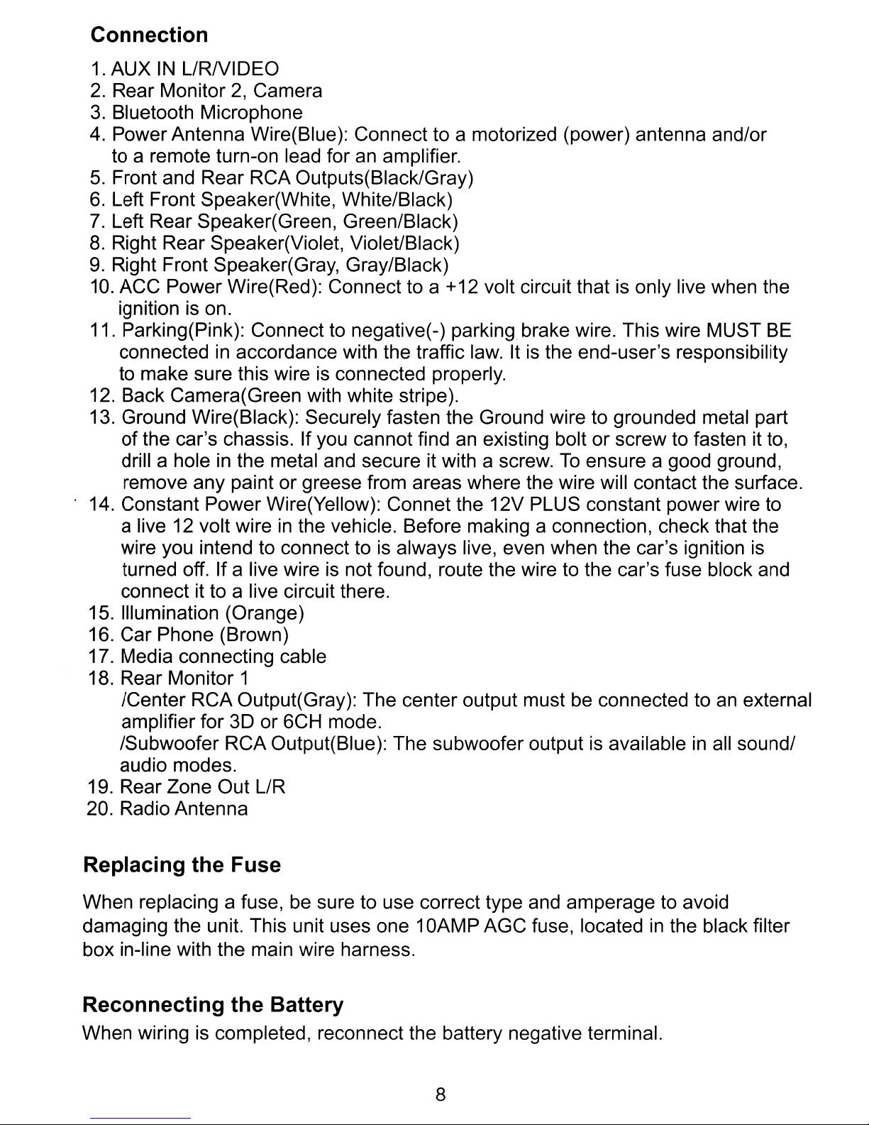
Connection
1.
AUX
2.
Rear Monitor2,Camera
3.
Bluetooth Microphone
4.
Power Antenna Wire(Blue): Connect to a motorized (power) antenna and/or
to a remote turn-on lead for an amplifier.
5.
Front and Rear RCA Outputs(Black/Gray)
6.
Left Front Speaker(White, White/Black)
7.
Left Rear Speaker(Green, Green/Black)
8.
Right Rear Speaker(Violet, Violet/Black)
9.
Right Front Speaker(Gray, Gray/Black)
10.
11. Parking(Pink): Connect to negative(-) parking brake wire. This wire MUST BE
12. Back Camera(Green with white stripe).
13. Ground Wire(Black): Securely fasten the Ground wire to grounded metal part
14. Constant Power Wire(Yellow): Connet the 12V PLUS constant power wire to
15. Illumination (Orange)
16. Car Phone (Brown)
17. Media connecting cable
18. Rear Monitor 1
19. Rear Zone Out L/R
20. Radio Antenna
IN
L/RNIDEO
ACC Power Wire(Red): Connect to a +12 volt circuit that is only live when the
ignition is on.
in
connected
accordance with the traffic law. Itisthe end-user's responsibility
to make sure this wire is connected properly.
of
the car's chassis. If you cannot find
drill a hole in the metal and secure it with a screw.
an
existing bolt or screw to fasten it to,
To
ensure a good ground,
remove any paint or greese from areas where the wire will contact the surface.
in
a live 12 volt wire
wire you intend to connect to is always live, even when the car's ignition
the vehicle. Before making a connection, check that the
is
turned off. If a live wire is not found, route the wire to the car's fuse block and
connect it to a live circuit there.
an
/Center RCA Output(Gray): The center output must be connected to
external
amplifier for 3D or 6CH mode.
in
/Subwoofer RCA Output(Blue): The subwoofer output is available
all sound/
audio modes.
Replacing the Fuse
When replacing a fuse, be sure to use correct type and amperage to avoid
damaging the unit. This unit uses one 1
box in-line with the main wire harness.
Reconnecting the Battery
When wiring is completed, reconnect the battery negative terminal.
OAMP
8
AGC fuse, locatedinthe black filter
Page 9

The buttons located on the
DD-858W
front display and the remote control that
perform the same function are assigned the same number for reference on the
diagrams and
r
r
PWR
MUTE
SRC
--=-
1
@
@
--=-
@
®
r
DIM
USB
I!
+
in
I
]
~~
AI
]
~
the text.
DD-858W
'E1!fD/
o
DVD
MULTI
6
MEDIA
A I
III
RECEIVER
I
IJ
r--
I---
s
....
'
l-
7
f-
s
....
z
-
@
-
-
.:
-
0
I!iJ
Unit Buttons
CD
Power On/Off, MUTE
@ SRC
@ Rotary Encoder (Volume Adjust)
@ Dimmer
® USB port
® Eject
(j) SD Card slot 1
@ SD Card slot 2
9
Page 10
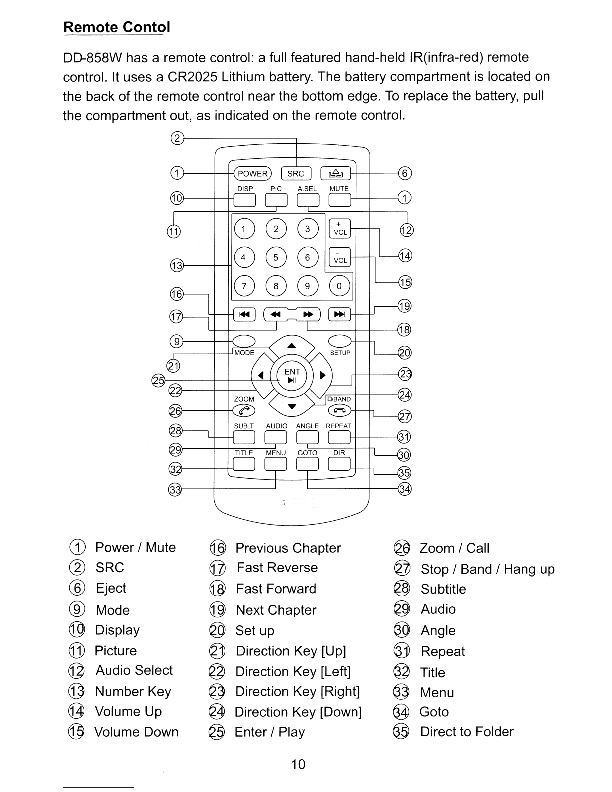
Remote Contol
DD-858W has a remote control: a full featured hand-held IR(infra-red) remote
is
control. It uses a CR2025 Lithium battery. The battery compartment
To
the back of the remote control near the bottom edge.
the compartment out, as indicated on the remote control.
2
r--------::=======t-
_
replace the battery, pull
located on
J-----+__+{
POWER
G)
Power / Mute
@
SRC
Eject @
®
Mode
®
Display
®
(j]
Picture
Audio Select
©
Number Key @ Direction Key [Right] @
©
g
Volume Up
@
Volume Down @ Enter / Play
Previous Chapter
®
Fast Reverse
©
Fast Forward
@
Next Chapter
Set up
®
Direction Key [Up]
~
@ Direction Key [Left]
@
Direction Key [Down]
10
@
Zoom / Call
Stop / Band / Hang up
©
@
Subtitle
@
Audio
Angle
®
Repeat
~
@
Title
Menu
@
Goto
@
Direct to Folder
Page 11

General Operation
Note: Some DVDs require specific operationorallow onlylimited operation during
playback which may not respond
occurs, the symbol appears on the TFTscreen, indicating that the operation
is notpermitted
by
the playerorthe disc.
POWER
1.
Press any buttonofthe unit to turn the unit on. The buttons on the frontofthe
unit light up and brand logo appears briefly
current mode status.
2.
Press the POWER button(1) again for more than two seconds to turn the unit
off.
MODE SELECTION
1.
Press MODE button(9) on the frontofthe unit or
the current mode icon at up-left corner
shown on the screen.
2.
Press the desirable mode icon at mode selection display.
remote control, Press Direction key(21-24) and ENT button(25) to select a
mode. (Some mode icon would be dimmed and the mode cannot be selected
for connection as Media, Camera, etc.)
3.
Or you can switch mode using SRC button(2). Press SRC button(2) on the
remote control to select a mode among currently available modes.
to
all operating commands. When this
in
the TFT screen followed by the
on
the remote control
of
screen. Mode selection display will
Orincaseofusing
or
touch
be
DIM ADJUSTMENT
Press DIM button(4) on front panel to adjust the display dim level. This unit has
5 steps of dim level.
AUDIO ADJUSTMENT
MUTE
Press MUTE button(1), audio will be blocked while mute icon
screen at any mode.
VOLUME
Adjust the unit's volume from Mute(lowest) to 40(highest) by turning Rotary
Encoder(3) to the right or left, or press the VOL
remote control. The TFT screen displays the volume level for 3 seconds and
disappears.
11
+NOL-
~
appears on
button(14/15)
on
the
Page 12
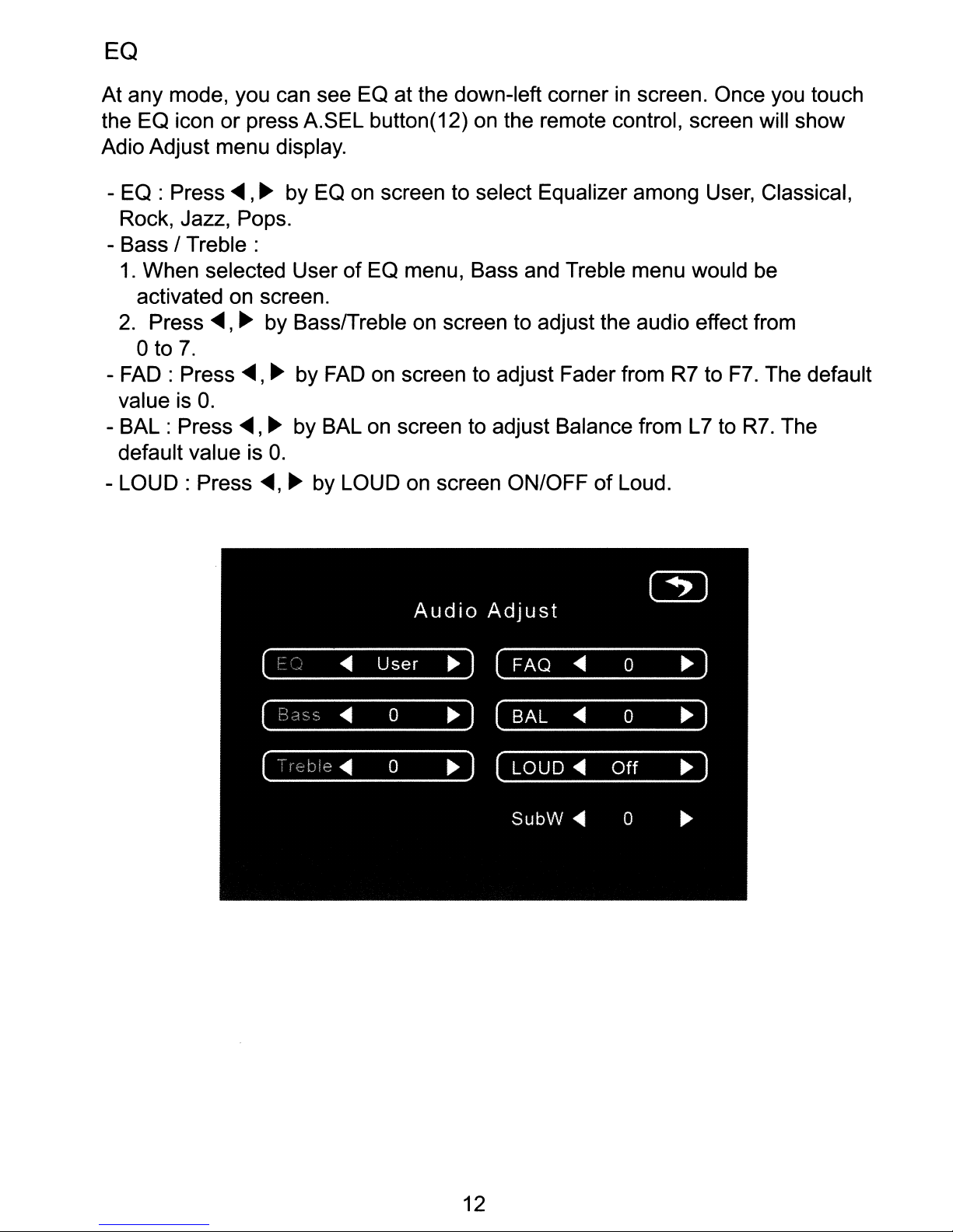
EQ
At any mode, you can see EO at the down-left cornerinscreen. Once you touch
the EO icon
Adio Adjust menu display.
or
press A.SEL button(12) on the remote control, screen will show
- EO : Press
<llII
,~
by EO on screen to select Equalizer among User, Classical,
Rock, Jazz, Pops.
- Bass /
1.
Treble:
When selected UserofEO menu, Bass and Treble menu would be
activated on screen.
2.
Press
oto
-
FAD:
value is
- BAL : Press
default value is
-
LOUD:
<llII
7.
Press
O.
Press
,~
by Bass/Treble on screen to adjust the audio effect from
<llII,
~
by
<llII,
FAD
~
by BAL on screen to adjust Balance from L7 to
on screen to adjust Fader from R7 to F7. The default
O.
<llII,
~
by LOUD on screen ON/OFF
of
Loud.
R7.
The
12
Page 13
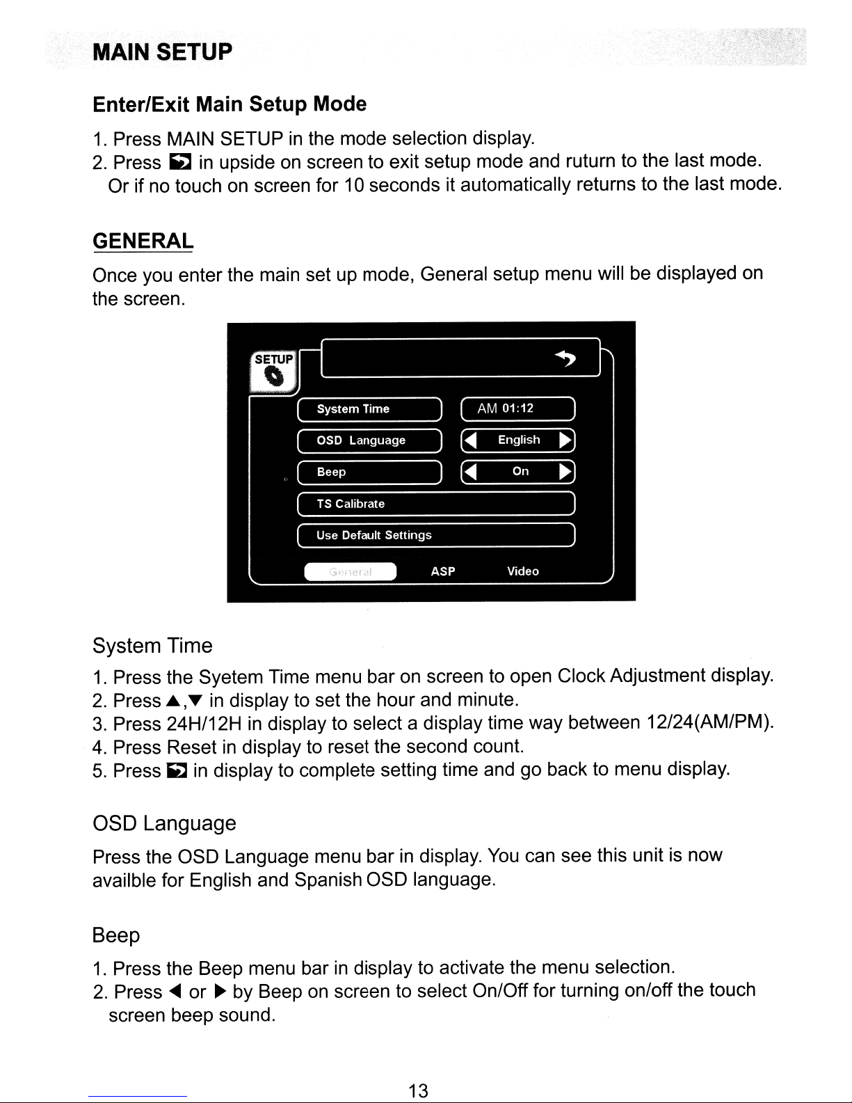
MAIN SETUP
Enter/Exit Main Setup Mode
1.
Press MAIN SETUPinthe mode selection display.
2.
Press
Or
GENERAL
Once you enter the main set up mode, General setup menu will be displayed on
the screen.
~
in
upside on screen to exit setup mode and ruturn to the last mode.
if no touch on screen for 10 seconds it automatically returns to the last mode.
System Time
1.
Press the Syetem Time menu bar on screen to open Clock Adjustment display.
2.
Press ~
3.
Press 24H/12Hindisplay to select a display time way between 12/24(AM/PM).
4.
Press Reset in display to reset the second count.
5.
Press
,T
in display to set the hour and minute.
~
in display to complete setting time and go back to menu display.
OSD Language
Press the OSD Language menu barindisplay.
availble for English and Spanish OSD language.
You
can see this unit is now
Beep
1.
Press the Beep menu barindisplay to activate the menu selection.
2.
Press
screen beep sound.
....
or~by Beep on screen to select On/Off for turning on/off the touch
13
Page 14
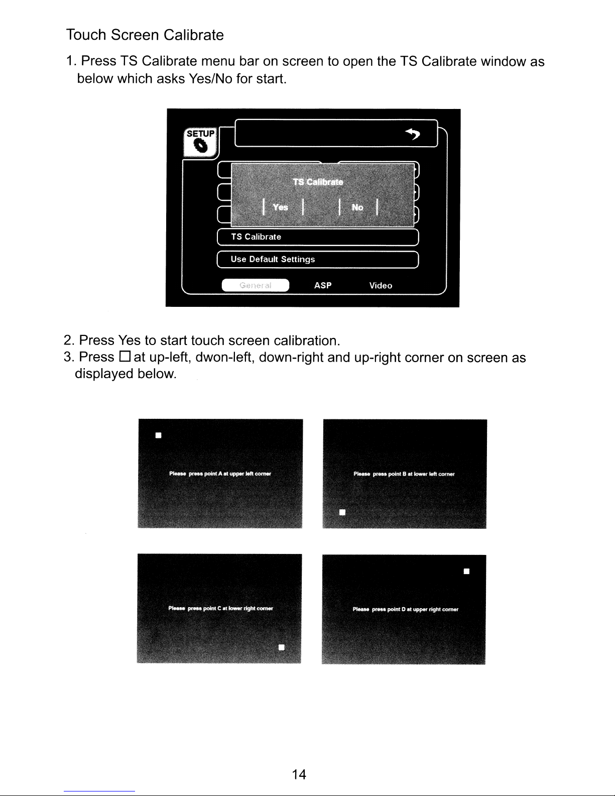
Touch Screen Calibrate
1.
Press TS Calibrate menu bar on screen to open the TS Calibrate window as
below which asks Yes/No for start.
2.
Press Yes to start touch screen calibration.
3.
Press D at up-left, dwon-Ieft, down-right and up-right corner
displayed below.
on
screen as
14
Page 15

User Default Settings
1.
Press User Default Settings menu bar on screen to open the
window
asks Yes/No.
2.
Press Yes for start resetting. The unit will be resetted and automatically off.
ASP (Audio Setup)
which
Enter the Main Setup mode and press
ASP
at downsideofscreen to display
audio setup menu.
- Bass Center Frequency / Bass
Q Value / Bass DC Gain / Treble Center
Frequency/ Loud Center Frequency
Press
~
,~
at the menu bar on screen to adjust the audio effect setting value.
- Power On Volume / Fixed Volume
1.
Press
power on. You can select Fixed
~,~
by Power On Vol menu bar on screen to set the volume when
or
Last Volume.
2. If you select "Fixed" at Power On Vol setup menu, you can select the volume
level. Press
~.
by Fixed Vol menu bar on screen.
VIDEO
Enter the Main Setup mode and press Video at downsideofscreen to display
audio setup menu.
Display Mode
Press
16:9
or
~,~
4:3.
by Display Mode menu bar on screen to select the display aspect
of
15
Page 16

Camera Image
Press
<lllII,
~
by Camera Image menu bar
on
screen to select Normal or Mirror.
If you select "Mirror", the image reflected by camera will
image seen through mirror.
be
reversed as the
16
Page 17

Radio Operation
Switch to Radio Mode
When you turn
When switching the other mode to radio mode, press MODE button(9)
remote control or touch the mode icon at up-right side
selection display, and press radio mode icon.
on
the unit, radio mode will displays
-
...
~=
~.
FM-3
106.70MHz
DX
P01
AM
1 2
24
[I
1
2
3
4
5
on
screen first.
of
screen to go to the mode
BAND ISCAN ISETUP
87.50MHz
90.10MHz
106.70MHz
108.50MHz
110.10MHz
I]
I~
....
•
...
~
LOCIDX
IAS/PS SEEK/\
~UNEV
ITUNE/\ I
SEEK
vi
in
the
Select Band
Press BAND button(27)
band will change among 1AM band and 3
on
the remote control or BAND
FM
bandsindisplay.
on
screen, the current
Scan
Press SCANindisplay to start scanning broadcasting stationsinthe current
band.
Manual Tuning
Press TUNE
up/down manually by one step.
1\,
TUNE
vat
downsideindisplay to change the radio frequency
Seek
1.
Press SEEK
up/down. When strong signal's radio station
each.
2.
Press SEEK
listen to the current broadcast.
1\,
SEEK v at downsideindisplay to seek the radio frequency
is
found, it stops for 3 seconds
1\,
SEEK v again or ENTER button(25) to stop seeking and
17
Page 18

Adjust Sensitibity
1.
OX
is default as displayed on screen. When selected LOC, the sensitivity will
decrease
broadcasting station.
2.
Press LOC/OX at downsideindispay to change the sensibility.
of
20dB.
You
can select LOC when operating SEEK near
Stereo Broadcast (ST)
When ST appears at upsideofdisplay, it's stereophonic broadcasting. If not, it's
monophonic broadcasting.
Using Preset Stations
Ten
stations are preset and recall stations for each band.
All ten stored stations for the current band appear on the
TFT screen.
.Storing Stations
1.
Select a band(if needed), then select a station.
2.
Press to hold
in
display (Press T at leftsideofthe list, if needed) for 3 seconds to store
each station's frequency to the number.
3.
To
listen to a corresponding stored station, press
control or
1-10
1-0
buttonsinremote control or
in
display.
1-10ofstation list at leftside
1-0
buttonsinremote
Auto Store (AS)
Use Auto Store function to select six strong stations and store them automatically
in
current band.
1.
Select a band (if needed).
2.
To
activate Auto Store function, press AS/PS at downsideindisplay for 3
seconds. The new stations replace the stations already stored
in
that band.
Preset Scan (PS)
Scan stored stationsinthe current band.
1.
Select a band (if needed).
2.
Press AS/PSindisplay, the unit pauses for 3 seconds at each preset station.
3.
Press AS/PS again to stop scanning when a desired stationisfound.
18
Page 19

RBDS Operation
TA
(Traffic Announcement)
TA lets you receive traffic announcements automatically, no matter what source
you are listening to at the moment. TA can be activated for both a TP station or
an enhanced other networks TP station.
-
To
turn TA off/on, touch TAinscreen.
- When recieving Traffic Announcement, if the volume is low than 16, it will be
changed to 16. And, except Volume and MENU control functions, other control
can not be operated by screen, remote control and the unit, until TA is turned
off.Ifyou press other key during TA is on, unit will sound warning beep.
* Refer to Radio part for other functions as AS/PS, TUNE, SEEK, etc.
in
Press NEXT
REG (Regional Mode)
When AF is used to retune frequencies automatically, the regional function limits
the selection to stations broadcasting regional programs.
-
To
turn REG off/on, touch REGinscreen.
screen to display the menu.
AF(Alternative Frequency)
When switching to RBDS mode, AF is flickering and on as a default.
When AF is on, if the current signal is weak or there are other problems, the unit
will automatically search for a different station
stronger signal.
-
To
turn off/on, touch AFinscreen.
in
the same network which has a
PTY(Program Type)
You
can turnina station by using PTY information.
in
or
screen.
Tat
be
displayed on screen.
leftsideofscreen to select a program type.
You
can search for a specific type
- Sport
- Touch PTY
- Program type list will
of
broadcasting program, such as those listed on the next page.
- Touch ...
- After choosing type of program, you can tune or seek station within the selected
type.
- Program Type List
- None - News - Affairs - Info
- Educate- Drama - Culture - Science
- Pop M - Rock M - Easy M - Light M
- Other M - Weather - Finance - Children
- Religion - Phone
- Country - Nation M - Oldies - Folk M
In
- Trevel - Leisure
19
- Varied
- Classics
- Social
- Jazz
- Document
Page 20

TAVolume
AM
06:
:,l}
I
BANDISCANISETUP
-You can select volume between
Clock Tune
-Select "On", when you drive to different place, the clock can adjust automatically.
TA Option
-Seek/Alarm.
TA
Retune
-Long/Short.
0-39.
~
II
nil
~
~
~
~
~
~
~
RADIO
~
~
~
20
Page 21

CD Player Operation
Switching to CD Mode
Press
of
(DVD
MODE
screentogo
mode
icon is only activated
button(9)inremote control
or
touch the
to the mode selection display, and press
when
already inserted a disc.)
mode
DVD
icon
Disc Insert/Eject
1.
Place CD, label side up, into
2. After inserting the disc, playback starts automatically and the
playback display shows.
3.
To
stop
the
playback and eject
AM
rill
•
CODA
Track
Time
Rep
Mode
3/60
000031
Off
Normal
08:03
the
disc
slot.
the
disc, press Eject button(6).
SETUP
1.
Track01
2.
Track02
cda
cda
~
....
~
4.
Track04
5.
Track05
cda
cda
...
liiii:II
~
at
mode
CD
up-right corner
icon.
mode's
~
~II
./~
I
I+ll
I I
~
I
Return
Play/Pause
1.
Insert a CD, the unit will play it automatically.
2.
When
playing a disc, press once
~II
button(25) on remote control
screen to pause, and press again to play again.
3.
Track list will be displayed at right side
.,
...
to
move
to previous/next
track
of
screen.
and press ....,~~to
track list. Press the track you desired directly to play.
Stoping play
Press - button(27)inremote control
press twice to stop playing.
or
-/.
Moving Track
in
display
NEXT
I
When
or
~II
moving track, press
move
once
to previous/next
for
prestop, and
in
1.
Press~.. button(16) or~..
2.
Press
~~
button(19)
or
in display to move to previous track.
~~
in
display to move to next track.
21
Page 22

Fast Forward/Fast Reverse
1.
Press
~~
button(17)inremote control or NEXT,
~~
in
screen for fast reverse,
increasing playback speed rate at X2, X4, X8, X16, Play(normal) by pressing
more.
2.
Press
~~
button(18)inremote control or NEXT,
~~
in
screen for fast forward,
increasing playback speed rate at X2, X4, X8, X16, Play(normal) by pressing
more.
Repeat Play
1.
Press REPEAT button(31)inremote control or NEXT, REPEATinscreen to
repeat the current track. "Repeat Single" will
2.
Press again to repeat the full contents of disc. "Repeat All" will displayed.
3.
Press third time to go back normal play. "Off' will displayed.
be
displayed shortly on screen.
Random Play
1.
Press NEXT, E:aindisplay to play all tracks
"Random" on screen.
2.
Press again to release random play function, displaying "Normal" on screen.
on
the discinrandom, displaying
Intra Scan
1.
When disc playback, press NEXT, INTRO belowindisplay to play
on
each from current track. "Intro" will be displayed shortly
2.
Press INTRO again to stop scanning, displaying "Intro Off' on screen.
GOIO
You
1.
Press Number key(13) and ENT button(25)inremote control to play the
(Direct Access)
can select the desired track directly.
screen.
track.
2.
Or press GOTO button(34)
in
remote control or Track displayinscreen for
opening direct access key pads(1,2,3,4,5,6,7,8,9,O, RTN, ENT). Press the
in
track number using Number key(13) and ENT button(25)
key pad
in
screen for playing.
•
CODA
Track
Time
Rep
MOde
AM
3/60
000031
Off
Normal
08:03
1.
2.
~
4.
5.
TakeMeHome
Good
Heart
Girl
One
Warl
SETUP
~
......
.....
~
remote control or
10
seconds
~
....
~
I
IRepeatl
::x:
Intra
I
I
NEXT
I
22
Page 23

MP3IWMA
Player
Operatan
You can play MP3/WMAfiles stored
in
disc/SO card/USB.
Functions as play, pause, stop, track selection, fast forward/reverse, repeat play,
intro scan, random play, etc. are the same for MP3/WMA with CD operation.
Please see the CD player operation section for the instruction about these
functions.
After MP3/WMA disc/SO card inserted or USB connected, "MP3" or "WMA" and
its information displays on screen and the file
in
disc will be played automatically.
Move Folder
When playing WP3/WMA, press
the playing and move to folder list.
* Note: CD-R/RW must conform to the
Joliet. When naming files, be sure the file name extension is "MP3" or "WMA".
~
in screen or press OIR button(35) to stop
IS09660
level 1 or level 2 format Romeo
I
AM0231
SETUP
23
Page 24

DVD Player Operation
Note: When the unit is properly installed, DVD video cannot be displayed
is
main TFT screen unless the parking break
applied. If you attempt to
on
playa
the
DVD while the vehicle is moving, the TFT screen displays "PICTURE OFF FOR
YOUR SAFETY" with a blue background.
* Rear video(installed for backseat), if applicable, will operate normally.
Functions as switching mode, disc insert/eject, play, pause, stop, selecting track,
fast forward/reverse, etc. are the same for
CD
operation. Please see the
CD
player operation section for the instruction about these functions.
Enter DVD Root Menu
1.
Insert DVD disc and DVD menu will displayinscreen.
2.
Press Direction Key (21-24) and ENT button(25) to select menu and operate
it.
Or press the desirable menu
3.
If you want to go backtothe DVD root menuinthe middle
press MENU button(33)
in
on
screen to play
remote control or
NEXT,
it.
of
playing video,
ROOT on screen.
Display/Hide DVD Menu bars
in
screen
When playing DVD video, the screen hides DVD menu bars.
1.
Touch screen to display DVD menu bars
2.
Touch
on
~
to hide the menu barsinscreen.
screen, it disappears automatically.
on
screen.
Or,
after
10
seconds without touch
24
Page 25

Display DVD Information
Press INFOinscreen or DISP button(10)inthe remote controltodisplay DVD
information as title, chapter, audio, subtitle, etc.
on
screen.
Section A-B Repeat Play
You
can set a sectionintrack and play the section repeatedly.
1.
When playback, press A-Binscreen to initialize the starting point for section
in
repeat function, displaying "Rep A-"
2.
Press A-B again to memorize the ending point for sectional repeat function
and play the section, displaying "Rep A-B"
3.
Press A-B third time to release the function, displaying "Rep Off'inscreen.
screen.
in
sceen.
Go to Title Menu
Press TITLE button(32)inremote control or NEXT, TITLEinscreen to go to DVD
title's starting menu.
Press ANGLE button(30)
to view multiple picture angles recorded
Selecting Audio
Press AUDIO button(29) on remote control or
(repeatedly if needed,) to select
6Ch Eng on screen.
Selecting Subtitle
Press SUB.T button(28)inremote control or NEXT, SUB-Tinscreen repeatedly
to display subtitles recorded
Repeat Play
Press REPEAT button(31)inremote control or NEXT, RPTinscreen to select
Repeat Chapter - Repeat Title - Repeat All - Off.
in
remote control or NEXT, l!lI
in
discinsequence
NEXT,
an
audio kind and display audio information like
in
sequence.
25
in
screen repeatedly
..
AUDIOinscreen
Page 26

Zoom
Press NEXT,
L[4J
in
screen for zoominginscreen.
GOTO (Direct Access)
You
can select the desired track directly.
1.
Press GOTO button(34)inremote control for opening direct access display.
Title search menu highlighted and selected first
2.
- Using the remote control:
i.
Using Direction key(21-24), you can move the selection : Title - Chapter -
Time -
ii.
Press Number key(13) and ENT button(25) to go to the desired position
~. Select one ofTitle/Chapter/Time.
directly.
- Using touch screen :
i.
Touch the menu bar- Title/Chapter/Time to select the menu and open
number key pad(O-9, RTN, ENT).
ii.
Touch the desired number and
ENT.
in
the display.
26
Page 27

DVD SETUP
1.
When playing DVD/CD, press SETUP button(20)inremote control or press
SETUP
2.
After set up, to go back
control or
automatically go back
in
screen to show DVD SETUP display.
to
DVD playback, press SETUP button(20)inremote
~
at up-right side of screen. Or
to
DVD playback.
no
response for
10
seconds,itwill
DISC
Set Rating Password
1.
Press Set Rating PWD bar menuinscreen.
2.
Enter 8888 and ENTinthe keypad displayedinscreen.
3.
Press Set Rating PWD barinscreen again. The bar letters will change to
"Enter New PWD".
4. Enter 4 digit number which you want
screen.
to
set newly and ENTinthe keypad on
Parental Control
You
can set parental control for keep children from harmful video.
1.
Press Parental Control menu barinDVD setup display.
2.
Number keypad will be displayed for entering password before setting.
3.
Press
7.NC-17 I 6.R I 5.PG-R I 4.PG-13 I 3.PG I 2.G I Kid Safe.
~,~
by Parental Control to set one control grade among 8.Adult I
AUDIO ADJUSTMENT (DVD SETUP)
Downmix
1.
When the disc supports
5.1
CH
sound effect, Downmix menu would
27
be
Page 28

activatedinscreen. If itisdeactivated at the setup menu display, you cannot
is
select this menu option, while it
2.
Press
~
,~
by Downmix menu barinscreen to select On/Off.
already applied "On" automatically by unit.
Dolby Prologic
II
Dolby PrologicIItechnology processes any high quality stereo (2CH) movie
and music audio into five playback channels(5.1 CH)
of
full-bandwidth surround
sound. Therefore when listening to typical two-channel sources like CD, the
listener can enjoy a richer spatial effect.
1.
Press
* Audio Adjustment - Dolby Prologic
1.
Select "On"
2.
Press A.SEL button(12)inremote control
3.
Select your preferenceinthe Audio Adjust menu display by pressing Direction
key(21-24)
effect type
-
Mode:
~,
~
by PrologicIImenu barinscreen to select On/Off.
II
of
PrologicIIin
in
remote control or touching screen.
of
Dolby Pro LogicIIamong the menu as below.
Pro Logic / PUI Matrix / PUI Movie / PUI Music
DVD setup menu.
or
EQinscreen when disc playback.
You
can select the audio
- DRC : On / Off
- When you selected PUI Music mode, there would be activated some menu as
below.
PANOR : On / Off
Dim Ctrl : 0 - 6
C W
Ctrl:
0 - 6
* Audio Adjustment - Dolby 5.1CH
Some discs support 5.1-channel Dolby Digital surround sound. When this kind
disc inserted the unit, you can adjust the 5.1-channel audio effect
preference.
1.
It should be selected
5.1
enjoy
2.
Press A.SEL button(12)inremote control or
3.
Select your preferenceinthe Audio Adjust menu display by pressing Direction
key(21-24)
CH sound effect.
in
remote control or touching screen.
"Off"
of
PrologicIIand DownmixinDVD setup menu for
EQinscreen when disc playback.
- Volume: 0 - 40
on
your
of
- Left / Right / Center / L Surr / R Surr / SubW : -6 - 6
On
- DRC :
/ Off
28
Page 29

Video Type
1.
Press
Original/Height
~,
~
by Video Type menu barinscreen to select one type among Fill /
Fit / Width Fit / Auto Fit /
Pan
Scan.
Disc Language Setup
After language setup at DVD setup mode, when playing disc, the selected
language will be applied/shown. (if available at the disc)
- Subtitle / Audio / DVD
Press
~,
~
by the menu barinscreen to select a desired language.
Menu:
Speaker
After entering DVD setup mode, press Speaker belowinscreen to show speaker
setup menu.
Speaker Volume Setup
- Front Speaker: Press
- Surr Speaker: Press
- Center Speaker: Press
- Subwoofer : Press
~,~
~,~
~,
to select Large or Small.
~
to select Large or Small.
~,~
to select Large, Small or None.
to select Present or None.
29
Page 30

Test Tones
Press
...
,~by Test Tonesinscreen to select a speaker and perform test.
Bass Manage
1.
Press T at leftside of Speaker setup displaytoturn to the second page menu.
2.
Press
3.
When selected
Press
...
,~by Bass Manage menu bar to select Off/On.
On
at Bass Manage, Center Filter menu will be activated.
...
,~by Center Filter menu bar to select the center filter value of bass
from 80 - 300.
Speaker Delay
- Center Speaker
select the center speaker delay range.
- Surround Speaker
to select the center speaker delay range.
Delay:
Delay:
Press"',
Press"',
~
by Cent Spkr Delay menu barinscreen to
~
by Surr Spkr Delay menu barinscreen
Speaker Channel Gain
- Front Left Channel
adjust the front left speaker's volume effect.
- Front Right Channel Gain / Center Gain / Rear Left Channel Gain / Rear Right
Channel Gain / Subwoofer
1.
Press T at leftside of Speaker setup display to turn to the third page menu.
2.
Press
...
,~by
Subwoofer Gain menu bar
Gain:
FR
Press
...
,~by FL
Gain:
CH
Gain / Center Gain /
in
screen to adjust the speaker's volume effect.
CH
Gain menu barinscreen to
RL
CH
Gain / RR
CH
Gain /
30
Page 31

* Here are some tips for OSD(ON Screen Display). It is convenient for operation.
We can divide the screen into several areas as below.
-
A
D
Touch A area, launcher MENU will appear.
C
B
E
F
RADIO IMAIN
SETUpl
~~
USB
~
MEDIA
't
BLU
ETOOTH
Tounch B area, SETUP MENU will be showned(27).
Touch C area, DVD Menu will be showned(Page24 and 25).
Touch D area, you can operate Chapter down function.
SDI
•
It..
j-
AUXIN
SD2
•
Touch E area, you can operate Chapter up function.
Touch F area, you can go to Search Menu(Page26).
31
Page 32

VCD
VCD is played at DVO mode. Switching mode and playback functions are the
same for CO/OVD player operation.
Player
Operation
Audio
When playing VCD, press NEXT, PSCinscreen to select the audio speaker
effect. (Left
I Right I Mix I Stereo)
PSC
When playing VCD, press
display.
Available when the disc over VCD 2.0 disc and PSC (Play Sack Control)
recorded.
NEXT,
PSCinscreen to go to VCO starting menu
32
Page 33

You
can see JPEG file storedindisc/SO card/USB.
When using a disc, it should
be
operated
in
OVO
mode. When using
USB, select the corresponding mode at mode selection display.
SO
CARO or
Slide Show Operation
1.
When JPG modeisplayed, slide show will
stops for 5 seconds and goes to next file
name.
2.
Press
3.
Press - button(27)inremote control or
~II
button(25)
in
remote control or
and file list will be diplayed.
4.
Press
1oIII~
button(16)inremote control or
picture.
5.
Press
~~
button(19)inremote control or
Zoom In/Out
1.
Press ZOOM button(26)inremote control or
2.
Preess
~
in
screen for zooming out.
Rotating Display
be
operated automatically. A slide
in
alphabetical/number order of file
~II
in
screen to play/pause.
~I
in
screen to stop playing. Folders
1oIII~
in
screen to display previous
~~
in
screen to display next picture.
~
in
screen for zooming in.
1.
Press
2.
The picture will be turned 90 degree each by pressing more.
~
in
screen to turn current picture 90 degreeina clockwise direction.
33
Page 34

USBISO
Card Operation
Switching to USB /
Press MODE button(2)
SO
Card Mode
or
press the current mode icon at up-leftofscreen to go
to mode selection display and press USB / SO card mode icon.
Play Each Source
According to the source storedinUSB
The source types compatible with this unit are
or
SO
card, you can play it.
in
specification on
AM 08,
30
SETUP
page.
34
Page 35

Bluetooth
Operation
This unit supports Bluetooth wireless connection with a bluetooth cellular phone.
Note:
- Before using the bluetooth function
in
unit, please check a microphone
installed to this unit.
- Digital noise
- Provides the best sound clarity with little
&echo suppression system built-in.
or
no distortion.
(Echo and side-tone might be sensible depending upon cellular phone's
or
characteristics
service networks)
- Full duplex conversation
- Bluetooth version
2.0
Switching to Bluetooth Mode
Press MODE button(2)inremote control or touch the current mode icon at
of
up-left corner
mode icon
AM
in
12:53
screen
screen.
to
go to mode selection display, and press BLUETOOTH
SETUP
Bluetooth Setup
Before using bluetooth functioninthis unit, you should first turn
function at Bluetooth setup menu.
1.
Press SETUPinscreen to display Bluetooth setup menu.
2.
Press
And then, three other bluetooth setup menu will
Bluetooth icon
- Auto
-Auto
- Bluetooth
from
...
,~
Connect:
Answer:
Level:
0-6.
by Bluetooth menu barinscreentoenable bluetooth function.
0 always appears at up-left corner(by mode icon)
Press ,~by Auto Connect menu bar to choose On/Off.
Press ,~by Auto Connect menu bartochoose On/Off.
Press"',
on
bluetooth
be
displayed below, and
in
screen.
~
by Bluetooth Level menu bar to choose the level
35
Page 36

Pairing
1.
Click Pairinscreen to have the unit prepare starting pairing.
in
It will display "Waiting for Pairing"
2.
Enable your cellular phone's bluetooth pairing. If the cellular phone requires
the pin code, enter 1 2
3.
It will display "Pair OK " on screen when the paring is completed.
*
In
caseoffailureofpairing
- Delete item
in
paired list on your Bluetooth cellular phone
34.
screen.
- Reset both cellular phone and this unit by switching on/off
- Restart pairing as per previous procedures.
* Should your cellular phone battery be at low charge, the Bluetooth connection
To
may occasionally be lost.
maintain good connectivity ensure that your
cellular phone battery is adequately charged.
Disconnect
To
disconnect Bluetooth link, just click DISCONNECTinscreen.
Make a Call
(unavailable if pass-word storedinthe cellular phone)
1.
Enter phone numbersinDial Padinscreen or by using remote control.
-
+-
in
screen means erasing a number just entered.
2.
Press Pick Up
3.
Talk through the supplied microphone.
3.
Press Hang Up
call displaying "Call End"
in
screen or 0 button(26)
in
screen or e button(27)
in
screen.
in
remote control for calling.
in
remote control to hang up the
Receive a Call
1.
When the unitisringing, "Answer?" appearsinscreen.
Press Pick Up
- If ringing
into Bluetooth mode. After phone talking, it also resume back to the previous
mode after 5 seconds delay time as below image.
- Even though making a call by cellular phone, not by this unit, this unit would
activate automatically, showing "Talking"
2.
Talk through the supplied microphone.
3.
After finishing conversation, press Hang Up
remote control to hang
in
screen or
in
other mode sucKas DVD, Radio,... this unit automatically change
~
button(26)inremote control for calling.
in
screen.
in
screen or ® button(27)
up
the call displaying "Call End"inscreen.
in
36
Page 37

Transfer a Call between Unit and Phone
During conversation, for privacy or any other reason, you can transfer the call
between the unit and your cellular phone by pressing
I~
in
screen.
A2DP
The function to play audio files storedincellular phone
In
this mode, operate the following 5 functions.
..
~
previous track
~H
next track
~
play
II
pause
• stop
* Some kinds
of
cellular phone are not compatible A2DP function with this unit.
37
Page 38

Media Operation
Note:
You
-
- After connecting Media Player, the current mode will change to Media mode
~
- When the Media Player's internal battery becomes depleted, the Media Player
- Playback functions as play, pause, stop, track selection, fast forward/reverse,
should connect your Media with this unit first using the cable supplied.
and the unit will start playing the selected list or play all files registered on the
Media if no selected list.
The unit will not operate, or may operate improperly with unsupported versions.
cannot be played even if connected to the unit. This unit cannot be used to
recharge the Media Player.
repeat play, intro scan, random play, etc. are the same for Media and CD/DVD
operation. Please see the CD/DVD player operation section for the instruction
about these functions.
AM
03:12
m=
Folder:
1. Falling Rain
2. Big
3.IWanttoGo
[I
4.
5. Bad
I+lII
~
MUSIC
Track
Time
Rep
Mode
~II
3/60
00:00:31
Off
Normal
I
•
I I
Switching to Media Player Video/Audio Mode
Songs
World
TakeMeHome
Boy
tJ+I
Video
I
Return
ISETUP
I]
NEXT
I
.~
~
.....
T
~
1.
Press VIDEOinscreen
signal input from Media Player.
2.
You
cannot operate the Media video playback functions by this unit.
operate the video playback functions by your Media Player.
3.
If you want to go back to Media audio mode, press Audioinscreen.
on
Media Player audio mode to standby for video
38
You
should
Page 39

SETUP
1.
Press SETUPinscreen to open iPod setup menu display.
2.
Press
If you select Off, when you connect iPod to this unit, the mode will not
automatically
<llIII,
~
by Auto Connect menu bar to select On/Off. The defaultisOn.
be
..
,...
8==
changed, while you should switch the mode manually.
1
~
ill!
~
Media
~
39
Page 40

Troubleshooting·
Problem Cause Corrective Action
No power to unit
Fuse(s) blown
Speakers are not wired Connect speaker harness;
correctly check speaker wires
Check/replace fuse(s)
fuse box
in
vehicle
No sound can be heard
or the volume is low
Will not read disc
The sound "skips"
during disc play
Speaker wires shorting to
chassis ground or to each
other
Fader or Balance incorrectly Check audio settings
adjusted
AV1
orAV2 not wired
correctly
Disc is upside down Insert disc right side up
Disc
is
dirty
Format not supported by
player
Disc is dirty
Receiver mount is not solid
or backstrap is not secure
Check splices, insulate all bare wires
Check wiring
Clean/inspect disc
Insert correct disc format
Clean/inspect disc
Check mounting and backstrap,
tighten if needed
DVD will not play
main screen
Remote control does
not work
The display is dark
Touch points
are not correct.
in
screen
on
Parking brake not applied
Batteries are weak Check/replace batteries
is
Sunlight
infrared sensor
Direct sunlight reflecting off
screen
Color/Brightness settings
incoreect
interfering with
Apply parking brake
Ifsunroof is allowing too much light,
close it partially or fully.
Close windows
Close windows and/or sunroof
Adjust Color/Brightness settings
Adjust the touch points at setup mode.
40
Page 41

Specifications
CEA Power Ratings
Power Output: 18watts RMS x 4channels into 4-ohms @ < 1% THD+N
Signal to Noise Ratio: 70dBA below reference (Reference: 1watt, 40hms)
Dynamic Power: 36watts
Frequency Response: 20Hz - 20kHz (-3dB), AudioNideo input used as source reference
Standard Power Supply: 14.4 VDC
CO/OVO Player
Compatible Disc: CD-R, CD-RW, DVD-R, DVD-RW
Compatible Format: DVD-VIDEO, SVCD, VCD, CODA, MP3, WMA,
JPEG, MPG, MP4,
Signal to Noise Ratio:
Frequency Response: 20Hz - 20kHz, -3dB
Channel Separation:
D/A Converter: 24bit
@ 40hms x 4channels
> 90dBA
> 60dB @ 1kHz
OAT,
AVI
SO
Card
Compatible Format: MP3, WMA, JPEG, MPG,
OAT,
AVI
USB
USB 2.0 Compatible
OAT,
Compatible Format: MP3, WMA, JPEG, MPG,
AVI
Video Format
CODEC FILE TYPE Bitrate (upto)
MPEG1
MPEG2
MPEG4
*.MPG
*.DAT
*.VOB
*.MPEG
DISC
~4Mbps
~4Mbps
~4Mbps
~4Mbps
~2
5Mbps
USB/SD
~1.5Mbps
~1.5Mbps
~1.5Mbps
~1.5Mbps
~1
5Mbps
Resolution
352 x 240
352 x 240
720 x 480
720 x 480
720 x 480
Subtitle Format
SMI/SRT/TXT/PSB/ASS/SSA/SUB
English 58 letters I Korean 29 letters
Name of Video file and Subtitle file should be the same.
Frame/sec
30fps
30fps
30fps
30fps
30fps
*
It
can be not playable according to the viedo file's types or recording ways.
Video
Format: NTSC/PALIAUTO
Output: 1 Vp-p (750hm)
Input: 1 Vp-p (750hm)
41
Page 42

FM Tuner
Tuning Range: 87.5 - 107.9MHz
Mono Sensitivity (-30dB): 9dBf
Quieting Sensitivity (-50dB): 15dBf
Alternate Channel Selectivity: 70dB
Signal to Noise Ratio @ 1kHz: 58dB
Image Rejection: 60dB
Stereo Separation @ 1kHz:
Frequency Response: 50Hz - 15kHz, -3dB
> 30dB
AM Tuner
Tuning Range: 530 - 1720kHz
Sensitivity (-20dB): 30uV
Signal to Noise Ratio @ 1kHz: 50dB
Image Rejection: 60dB
Frequency Response: 50Hz - 2kHz, -3dB
Monitor
Screen Size: 5.8" (Measured diagonally), 16:9 Widescreen
5.8"(145mm)H x 3.5"(89mm)W
Screen Type: TFT Liquid Crystal Display (LCD) Active Matrix
DVD Player: 400(H) x 234(W) X 3(RGB)
Back Light: CCFL, 350cd/m2
General
Audio Input Impedance: 10k
Power Supply:
Fuse: 10amp, ATO type
DIN chassis dimensions: 178mm(W) x 160mm(D) x 100mm(H)
11-16
VDC, negative ground
42
Page 43

Page 44

V,lLOR
MULTIMEDIA
Valor
Warranty
Validation
Dept
18061
ArenthAve
CityofIndustry.CA
91748
Place
Postage
Here
V,lLOR
ULT
EDI
ONE
YEAR
LIMITED
WARRANTY
Page 45

Please
complete
all
fieldstovalidate
your
Valor
Multimedia
limited
warranty.
Remembertoincludeacopy
of
your
dated
sales
invoice.
Failuretoreturn
this
card
will
resultinwarranty
coverage
startingonthe
date
of
manufacture
basedonyour
serial
number.
Special
warranty
provisions
will
onlybehonoredifthis
card
is
returned
complete.
Limitationstowarranty
periods
and
exclusions
may
not
applytoyour
area
if
applicablebylaw.
Please
check
with
your
local
regulatory
offices
for
details
regarding
warranty
regulations
in
your
area.
RETAILER
NAME
RETAILER
ADDRESS
RETAILER
PHONE
NUMBER
PRODUCT
PURCHASED
PRODUCT
SERIAL
NUMBER
DATEOFPURCHASE
NAME
DATE
SHIPPING
ADDRESS
(NOPOBOXES)
CITY
STATE
I
ZIP
CODE
PHONE
NUMBER
V/lLOR
MULTIMEDIA
ONE
YEAR
LIMITED
WARRANTY
Valor
Multimedia
hereby
warrantstothe
original
retail
purchaserofthis
product
that
should
this
productorany
part
thereof,
under
normal
use
and
conditions,be
proven
defectiveinmaterialorworkmanship
within
one
year
parts
and
labor
from the
dateoforiginal
purchase.
Such
defect(s)
will
be
repairedorreplaced
with
reconditioned
product
(at
Valor
Multimedia's
option)
for
parts
and
repair
labor.
This
limited
warranty
is the
purchaser's
exclusive
remedy for any such defect(s).
To
obtain
repairsorreplacement
within
the
termsofthis
warranty,
please
visit
www.valormultimedia.comorcontactusat
18061
Arenth
Avenue;City
ofindustry,
CA
91748
(626)
581-8900.
Proofofwarranty
coverage
(i.e.-
dated
billofsale) and a valid serial
number
is required.
This
warranty
does
not
applytoany
productofpart
thereof
which,inthe
opinionofValor
Multimedia,
has
sufferedorbeen
damaged
through
alteration,
improper
installation,
mishan
dling,
misuse,neglect,
accident,
or
by
removalordefacementofthe factory serial
number/bar
codelabel(s). The
opinionofValor
Multimedia
with
respecttothis
matter
shallbefinalTHE
EXTENT
OF
VALOR
MULTIMEDIA'S
LIABILITY
UNDER
THIS
WARRANTY
ISLIMITED
TO
THE
REPAIR
OR
REPLACEMENT
PROVIDED
ABOVE
AND,INNO
EVENT,
SHALL
THE
COMPANY'S
LIABILITY
EXCEED
THE
PURCHASE
PRICE
PAID BY
PURCHASER
FOR THE PRODUCT.
Warranty
Validation
Card
Why
did
you
choose
a Valor
Multimedia
product?
D
Appearance
D Value
D
Features
D
Brand
Name
D
Other
V/1LOR
MULTIMEDIA
I'IUV.-\(\
'\()
11(1.
Information gathered is used for the sole purposeofproduct registration. Your personal information will not be
sold or offered for telemarketing or contact unless you request
it.
THIS
WARRANTY
IS
IN
LIEU
OF
ALL
OTHER
EXPRESSED
WARRANTIES
OR
LIABILITIES.
ANY
IMPLIED
WARRANTIES,
INCLUDING
ANY
IMPLIED
WARRANTY
OF
MERCHANTABILITY,
SHALL
BE
LIMITED
TO
THE
DURATION
OF
THIS
WRITTEN
WARRANTY.
ANY
ACTION
FOR
BREACH
OF
ANY
WARRANTY
HEREUNDER,
INCLUDING
ANY
IMPLIED
WARRANTY
OF
MERCHANTABILITY, MUST BE
BROUGHT
WITHIN A
PERIOD
OF 18
MONTHS FROM THE DATE
OF
ORIGINAL PURCHASE.INNO
CASE
SHALL
THE COMPANY BE
LIABLE
FOR
ANY
CONSEQUENTIAL
OR
INCIDENTAL
DAMAGES
FOR
BREACH
OF
THIS
OF
ANY
OTHER
WARRANTY EXPRESS OR IMPLIED WHATSOEVER.
No
personorrepresentativeisauthorizedtoassume
for Valor
Multimedia
any
liability
other
than
expressed
hereininconnection
with
the
saleofthis
product. Some
jurisdictions
do not allow limitations on how long an implied
warranty
lastsorthe
exclusionoflimitationofincidentalorconsequential
damages
so the above limitationsorexclusions may not apply to you. This
warranty
gives you specific legal rights and you may also have
other
rights,
which
vary from jurisdiction to jurisdiction.
How
was
your
product
acquired?
Where
will
this
productbeused?
How
long
have
you
owned
your
vehicle?
Would
you
buy
another
Valor
product?
Would
you
recommend
a Valor
product?
D
Gift
D
Internet
Retailer
D
Standard
Retailer
D
Specialty
Store
D
Mass
MerchantfDiscount
Retailer
D
Personal
Automobile
D
RV
D Commerci'al Vehicle
D
Other
D
Brand
New
D
< I
year
D
1-
2
years
D
3 - 5
years
D
> 5
years
D
Yes
D
No
DYes
D
No
 Loading...