

Valor Coalflame BR627, Limousin BR627 Installer's Manual
INSTALLER GUIDE
COALFLAME
&
LIMOUSIN
600B607/05
MODEL BR627
(GC No. 32-032-22)
INSET LIVE FUEL EFFECT
GAS FIRE
AS SUPPLIED, TH IS APPLIANCE IS FOR USE WITH NA T URAL GAS
(G20)
WHEN CONVERTED USIN G VA LO R C ON VE RS ION K IT NO .591159 THIS
APPLIANCE IS FO R USE WITH PROPANE GAS (G31)
THIS APPLIANCE IS FOR USE IN THE UNITED KINGDOM (GB) AND
THE REPUBLIC OF IRELAND (IE) ONLY.
We trust that this Installer Guide g ive s suff icie nt de tai ls to enab le th e applia nce to b e
installed and maintaine d sat isfactori ly . However, if further inf ormation is required, our
Valor AdviceLine will be pleas ed to hel p.
Please telephone 0345 626341 (Local cal l rates apply ).
INSTALLER: Please leave this guide with the owner
© Valor Heating

INSTALLER’S GUIDE
Safety First.
Valor fires are CE Approved and designed to meet the appropriate B ritish
Standards and Safety Ma rks.
Quality and Excellence at the he ar t of every Valor fire .
All Valor fires are manufactured to the highest standa rds of qua lity and
excellence and are manufacture d unde r a BS EN ISO 9001 quality system
accepted by the British Standards Institute .
The Highest Standards
Valor is a member of the Society of British Gas Industrie s whic h works to ensure
high standards of safety, quality and pe rforma nce.
Careful Installation
Valor is a CORGI registered company. All our gas fires must be
installed by a competent CORGI Registered Installer in accordance
with our Installer Guide and should not be fitted dire c tly on to a
carpet or floor of combustible ma terial.
Valor Heating, Erdington, B irmingham B24 9QP
Because our policy is one of constan t deve lopment and improvem ent, details may vary
slightly from those give n i n this p ub licatio n
Page 2

INSTALLER’S GUIDE
CONTENTS
1 APPLIANCE DATA...............................................................................................4
2 GENERAL INSTALLATION REQUIREMENTS............................................5
3 PRELIMINARY CHECKS...................................................................................8
3.1 Unpacking............................................................................................................8
3.2 Check Ignition Spark...........................................................................................8
3.3 Check The Fireplace............................................................................................8
3.4 Fireplace Flue Pull...............................................................................................9
4 PREPARING APPLIANCE FOR INSTALLATION........................................9
4.1 Gas Supply Connection.......................................................................................9
4.2 Appliance Preparation.........................................................................................9
5 INSTALLATION TO FIREPLACE..................................................................10
6 BURNER & FASCIA INSTALLATION...........................................................12
6.1 Burner installation & Gas connection...............................................................12
6.2 Preliminary burner checks.................................................................................13
6.3 Reference Pressure Check.................................................................................13
6.4 Burner Trim Fitting ...........................................................................................14
6.5 Fascia Fitting......................................................................................................14
7 CERAMIC COALS INSTALLATION .............................................................15
8 FULL OPERATING CHECKS..........................................................................16
8.1 Check the control............................................................................16
8.2 Check For Spillage............................................................................................17
9 FINAL REVIEW ..................................................................................................18
10 SERVICING & PARTS REPLACEMENT......................................................19
10.1 To remove the ignition microswitch.................................................................20
10.2 To remove the gas shut-off microswitch ..........................................................20
10.3 To replace the control slide knob......................................................................20
10.4 To remove the burner unit.................................................................................21
10.5 To remove the electronic ignition generator.....................................................21
10.6 To remove the thermocouple interrupter block................................................22
10.7 To remove the pilot unit....................................................................................22
10.8 To remove the shut-off tap................................................................................23
10.9 To remove the gas flow rate controller.............................................................23
10.10 To remove the main burner injector...............................................................24
10.11 To replace burner plaques ..............................................................................25
10.12 To remove the appliance from the fireplace..................................................25
11 SHORT LIST OF SPARES.................................................................................26
Page 3
INSTALLER’S GUIDE
1 APPLIANCE DATA
This product uses fuel effect piec es conta ining Re fra c tory Ceram ic Fibre s (RCF), w hich
are man-made vitreous silica te fibre s. Exce ssive exposure to the se materia ls may c ause
temporary irritation to eyes, skin a nd re spiratory trac t. Conseque ntly , it make s sense to
take care when handling these articles to ensure tha t the release of dust is kept to a
minimum. To ensure that the release of fibres from these RCF articles is kept to a
minimum, during installation and servicing we recommend tha t you use a HEPA filtered
vacuum to remove any dust and soot a ccum ula ted in and around the fire be fore and afte r
working on the fire. When replac ing these artic les we recomm e nd that the replace d item s
are not broken up, but are seale d within a heavy duty poly the ne ba g, c learly labelle d as
RCF waste. This is not classified as “haz ardous w aste” and m ay be disposed of a t a tipping
site licensed for the disposal of industrial w a ste. Protec tive clothing is not re quire d whe n
handling these articles, but we rec omme nd you follow the normal hy gie ne rules of not
smoking, eating or drinking in the w ork a rea and al way s wash y our ha nds before ea ting or
drinking.
This appliance does not contain a ny compone nt m anufac ture d from asbe stos or a sbe stos
related products.
The appliance data label is on a tie below the burner a nd is visible when the bottom front
cover is removed.
Gas Natural (G20) Propane (G31)*
Inlet Pressure 20mbar 37mbar
Input - Max. (Gross) 6.85kW (23,400 Btu/h) 6.7kW (22,860 Btu/h)
Input - Min. (Gross) 2.7kW (9,410 Btu/h) 4. 3kW (14,670 B tu/h )
Burner Test Pressure (Cold) 17.3±0.75mbar
(7.0±0.3in w.g.)
Gas Connection 8mm pipe 8mm pipe
Burner Injector Bray Cat. 31 Size 440 Bray Cat. 15 Size 170
Pilot & Atmosphere Sensing
Device
Ignition Electronic
SIT Ref. OP9030 SIT Ref. OPLPG9222
(Battery 9V PP3)
35.1±0.75mbar
(14.1±0.3in w.g.)
Electronic
(Battery 9V PP3)
Aeration Non-adjustable Non-adjustable
*When converted using kit 591159
Page 4

INSTALLER’S GUIDE
2 GENERAL INSTALLATION
REQUIREMENTS
2.1 The installation must be in accordance with these instructions.
For the user’s protection, in the United K ingdom it is the law tha t all gas applianc es are
installed by competent persons in accordance with the current edition of the Gas Safety
(Installation and Use) Regulations. Failure to insta ll the appliance correctly could lead to
prosecution. The Council for the Re gistra tion of Ga s Installers (CO RGI) re quire s its
members to work to recognised standa rds.
In the United Kingdom the installa tion must a lso be in accorda nce with:
All the relevant parts of local regulations.
The current edition of the Building Regula tions issue d by the De partme nt of the
Environment and the Welsh O ffice or the Building Standa rds (Sc otla nd) (Consoli da tion)
Regulations issued by the Scottish Development Department.
All relevant codes of practice.
The relevant parts of the current editions of the following British Standa rds:BS 715 (Metal flue pipes etc.)
BS 1251 (Open fireplace com ponents)
BS 1289 Part 1 (Precast concrete flue s)
BS EN 1806 (Clay flue blocks)
BS 4543 Part 2 (Chimney linings)
In the republic of Ireland the installa tion must also c onform to the rele vant parts of:
a) The current edition of IS 813
b) All relevant national and local rules in force.
2.2 If the appliance is inte nded to be installed to a chimney which was previously
used for solid fuel, the flue must be swept clean prior to insta llation. All flues should be
inspected for soun dness and freedom from blockages.
2.3 The minimum effective height of the flue m ust be 3m.
2.4 Any chimney dampers or restrict ors should be removed. If removal is not
possible they must be fixed in the ope n position.
BS 5440 Part 1 (Installation of flues)
BS 5440 Part 2 (Ventilation)
BS 5871 Part 2 (L.F.E Installa tion)
BS 6461 Part 1 (Masonry chimney s)
BS 6891 (Gas pipework)
2.5 In the United Kingdom (GB) no specia l ve ntilation bric ks or vents a re re quire d in
the room for this appliance.
In the Republic of Ireland (IE), permane nt ventilation must c omply with the regula tions
currently in force.
Page 5
INSTALLER’S GUIDE
(
)
2.6 Note that soft wall coverings (e.g.
embossed vinyl, etc.) are easily affected by heat.
They may scorch or become discoloure d w hen
close to a heating appliance. Please bear this in
mind when installing.
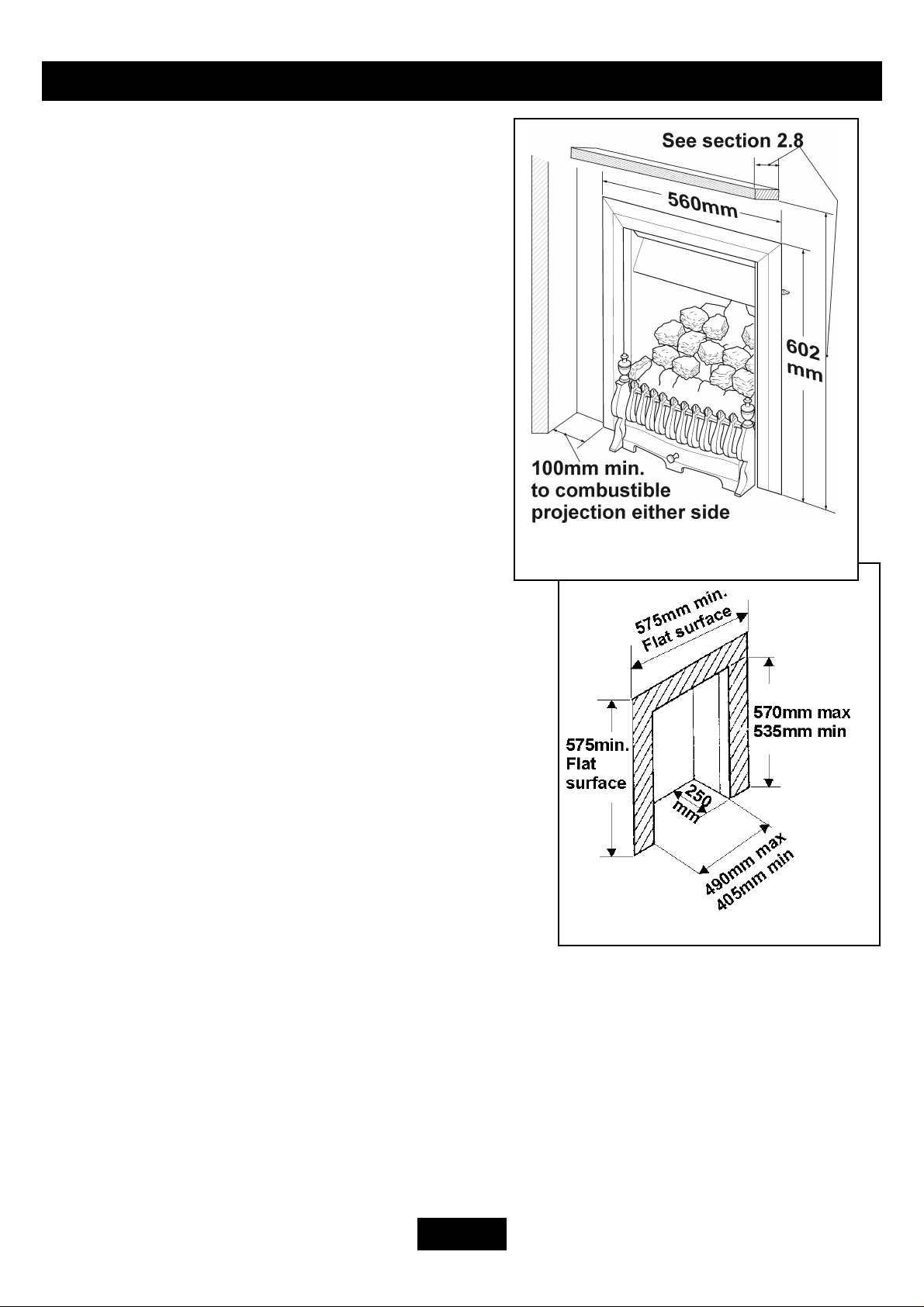
2.7 The minimum allowable distance to a
corner wall or other combustible projec tion from
the outside edge of the front surround at eithe r
side is 100mm. See figure 1
2.8 The minimum height from the top
surface of the hearth to the underside of any shelf
made from wood or other combustible m aterials
is as follows:-
• For a shelf up to 150mm deep: Minimum
height = 750mm.
• For a shelf deeper than 150mm: 750mm +
12.5mm for every 25mm depth ove r 150m m.
See figure 1.
2.9 The appliance must not be installed in any
room, which contains a bath, or show e r or where
steam is regularly present.
2.10 In the United Kingdom, as supplied, this
appliance can be installed in the following situations: -
2.10.1 A masonry chimney with a minim um
diameter of 175mm free from obstruction. Note the
flat surface area requirem ent (Figure 1a ). A masonry
chimney having a correctly insta lled flue line r to
BS715 and with a minimum flue diame te r of 125mm
Figure 1 Dimensions & cleara nces
Shown with Coalflame front
Figure 1a Masonry Firepla ce
is also acceptable. Chair bric k rem oval may not be require d providing a t lea st 50m m
clearance is available from the flue outlet to any fire plac e com ponent. This applia nce is
designed to cater for low lintel installa tions (minimum height 505mm) provided that a
minimum distance of 45mm is maintained between the lintel and the front face of the
fireplace – i.e the fire surround has a m inim um reba te of 45mm .
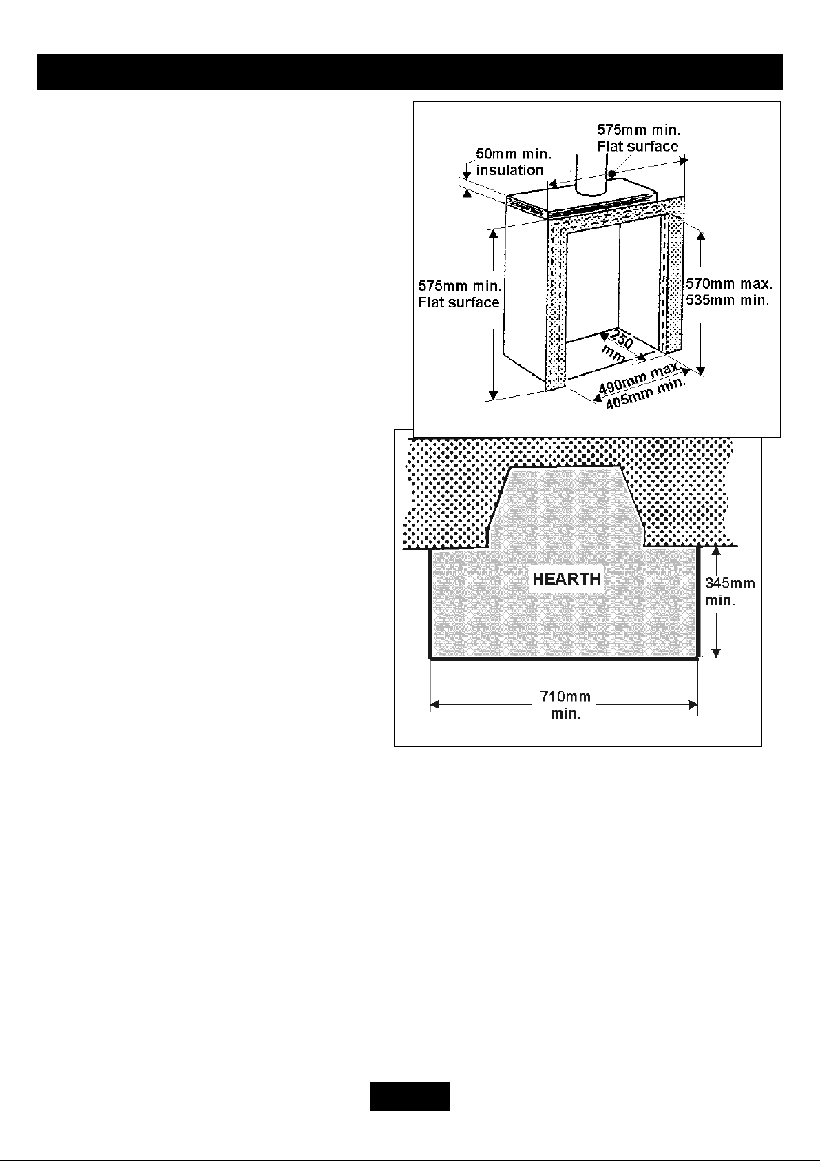
2.10.2 A twin wall metal flue sy stem conforming to BS715, the flue diameter being a
minimum of 125mm (See figure 2) w ith a minim um inte rna l depth of 250mm .
Incombustible mineral wool insulation of not le ss tha n 50mm thickness must be applied to
Page 6
INSTALLER’S GUIDE
the top surface of the system firebox a nd
must stand on a non-combustible ba se of
25mm thickness.
2.11 The appliance must be mounted
behind a non-combustible hea rth with
minimum dimensions as figure 3. (n.b
conglomerate marble hea rths are conside re d
as non-combustible). The applia nce ca n be
fitted to a purpose made proprietary cla ss
“O” 150°C surround. The hearth m ateria l
must be at least 12mm thick. The periphe ry
of the hearth (or fender) should be at least
50mm above floor level to discoura ge the
placing of carpets or rugs over it.
The appliance must not stand on
combustible materials or carpets.
The appliance must not be fitted
directly against a combustible wall. If
the appliance is to be fitted against a wall
with combustible cladding, the cladding
must be removed from the area covered
by the appliance outer surround. We
suggest that the actual surround is use d as
a template to mark the area for
combustible cladding rem oval.
2.12 The flue must not be used for any
other appliance or application.
Figure 2 Metal flue box
Figure 3 Hearth minimum dime nsions
2.13 If the fireplace opening is of underfloor dra ught ty pe, it m ust be sealed to stop a ny
draughts.
2.14 An extractor fan may only be used in the same room as this applia nce, or in any
area from which ventilation for the appliance is taken, if it doe s not affec t the safe
performance of the appliance. Note the spilla ge test requireme nts deta iled further on in this
manual. If the fan is likely to affect the appliance, the a ppliance must not be insta lle d
unless the fan is permanently disconnec te d.
2.15 Propane gas appliances m ust not be installe d in a room, which is built e ntire ly
below ground level (see BS 5871 Pa rt 2).
Page 7
INSTALLER’S GUIDE
3 PRELIMINARY CHECKS
3.1 U npacking
Carefully remove the contents. Ta ke spec ial care in handling the ceramic coals. Take care
not to bend or distort the slide control linkage w hen handling the burne r and c onve ction
box unit.
Check that all the listed parts are prese nt and in good c ondition.
1 Front Casting Pack
1 Front Fascia
1 Engine Assembly
1 Front Burner Trim
1 Rear Ceramic Support
1 Olive and Nut
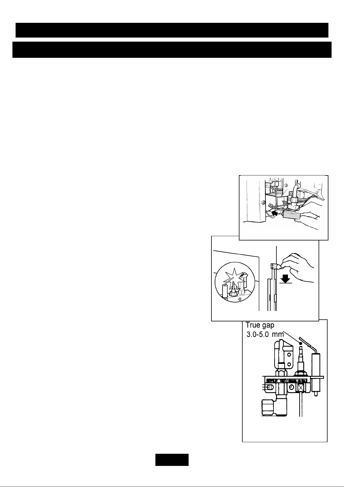
3.2 C heck Ignition Spar k
Before attempting to install, it is worth checking that the
electronic ignition system perform s satisfa ct orily.
3.2.1 Fit the battery to the ignition block locate d below the
burner tray at the left side. See figure 4. The positive terminal
(+) is to the right as you insert.
3.2.2 Depress the slider as far as it will go. This
should close the ignition circuit. Sparks should be se e n
tracking from the electrode pin to the therm ocouple tip.
See figure 5.
3 Self Adhesive Foam
Seals
2 Tension Cables
2 Cable adjusters
2 Eye bolts
2 Fibre Rawlplugs
1 Aluminium Sealing
Tape
2 Self tapping screws
1 9v (PP3) Battery
1 Literature Pack
Fig. 4 Battery Fitting
If there are no sparks make the following checks.
a) Check condition of battery and that it is correctly
fitted.
b) Check spark gap betwee n elec trode w ire and
thermocouple tip. See figure 6.
c) If a & b are satisfactory, check the ignition circuit and
components - see the servicing sec tion in this ma nua l.
3.3 C heck The Fireplace
The fireplace must comply with all the re quireme nts of sec tion 2.
The fireplace floor should be rea sona bly flat to ensure tha t the
convection box can be installe d without it rocking a nd so tha t a
good seal can be made at the bottom front of the box. The front
face of the fireplace should be rea sona bly flat over the area
covered by the convection box top and side fla nge seals to
ensure good sealing. These fac e s should be ma de good if
necessary. If the appliance is to be fitted against a wa ll with
Fig. 5 Slider control
Fig. 6 Pilot ignition
system
Page 8
 Loading...