

Valor 32-810-58, Churchill Installer's Manual
INSTALLER GUIDE
THIS APPLIANCE IS FOR USE WITH NATURAL GAS (G20)
THIS APPLIANCE IS FOR USE IN THE UNITED KINGDOM (GB) AND THE
REPUBLIC OF IRELAND (IE) ONLY.
INSTALLER: Please leave this guide with the owner
Manufactured exclusively for British Gas & Scottish Gas by Valor Heating
For Service Phone 0845 960 5040
Because our policy is one of constant development and improvement, details may vary
slightly from those given in this publication.
© Valor Heating
3002402/02
Churchill
Balanced Flue
(GC No. 32-810-58)
ROOM SEALED RADIANT/ CONVECTOR GAS FIRE
(Manufacturer ref. 4733)

INSTALLER’S GUIDE
Page 2
CONTENTS
SAFETY.....................................................................................................................3
LIST OF ACCESSORIES .......................................................................................3
1. APPLIANCE DATA......................................................................................... 4
2. GENERAL INSTALLATION REQUIREMENTS ......................................5
Terminal Position ............................................................................................... 9
3. UNPACKING..................................................................................................10
4. PREPARE THE FIRE ...................................................................................11
5. PREPARE THE WALL.................................................................................12
Cut the Flue Hole –Timber Frame Buildings .................................................14
6. PREPARE FLUE UNIT.................................................................................15
7. TERMINAL GUARD FITTING................................................................... 18
8. CHECK IGNITION SPARK......................................................................... 19
9. CONNECT TO THE GAS SUPPLY ............................................................ 19
10. FITTING COALS........................................................................................... 20
11. CHECK APPLIANCE OPERATION..........................................................23
12. CHECK THE REFERENCE PRESSURE ..................................................23
13. REPLACE OUTER CASE ............................................................................24
14. MAKE FINAL CHECKS AND INSTRUCT USER ................................... 24
15. SERVICING.................................................................................................... 25
15.1 To Remove Outer Case. .......................................................................... 25
15.2 To Remove Window Unit .......................................................................25
15.3 To Remove The Ceramic Fuel Items ......................................................25
15.4 To Remove Burner(s) .............................................................................. 25
15.5 To Remove Injectors(s) ...........................................................................26
15.6 To Remove Thermocouple......................................................................26
15.7 To Remove Electrode Pin........................................................................ 26
15.8 To Remove Pilot Pipe & Jet ....................................................................26
15.9 To Remove The Gas Tap And Piezo Unit............................................... 26
15.10 To Remove The Piezo Generator ............................................................27
15.11 To Grease The Control Tap .....................................................................27
SHORT LIST OF SPARES ...................................................................................28

INSTALLER’S GUIDE
Page 3
SAFETY
Installer
• Before continuing any further with the installation of this appliance please read
the following guide to manual handling
• The lifting weight of this appliance is 23 kg. One person should be sufficient to
lift the fire. If for any reason this weight is considered too heavy then obtain
assistance.
• When lifting always keep your back straight. Bend your legs and not your back.
• Avoid twisting at the waist. It is better to reposition your feet.
• Avoid upper body/top heavy bending. Do not lean forward or sideways whilst
handling the fire.
• Always grip with the palm of the hand. Do not use the tips of fingers for support.
• Always keep the fire as close to the body as possible. This will minimise the
cantilever action.
• Use gloves to provide additional grip.
• Always use assistance if required.
LIST OF ACCESSORIES
Description Part number
Timber frame Flue Clearance kit. 0583141
This kit includes : -
1 off Flue clearance sleeve
1 off Drip collar
1 off External wall plate
1 off Insulation blanket (This can be discarded)
For timber framed installations see section 5.
INSTALLER’S GUIDE
Page 4
1. APPLIANCE DATA
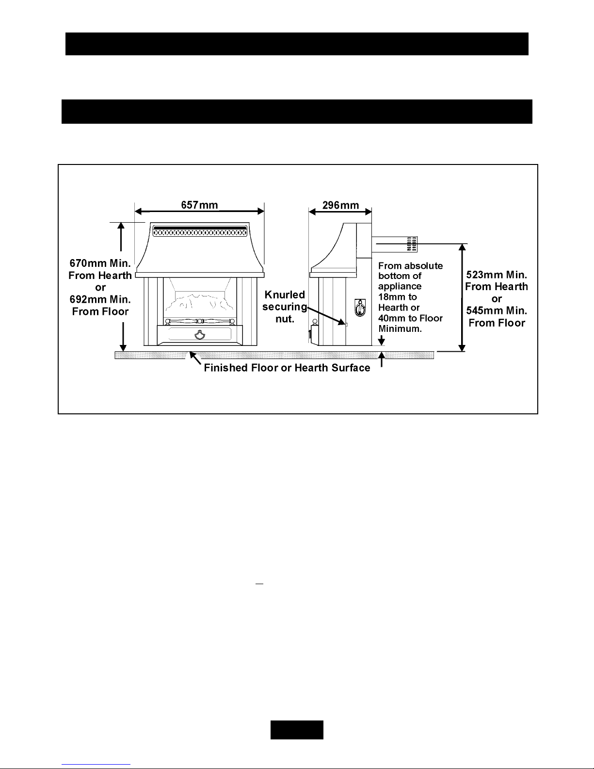
The overall dimensions are shown in figure 1.
Main Burner: Simplex aerated
Flame Effect Burner: Simplex aerated.
Gas Connection: RP 1/4 (1/4in. B.S.P) Isolating Elbow (Female).
Gross Gas Consumption: 4.9kW at maximum position.
Maximum output: 3.54kW
Injectors: -
Main Burner: Bray Cat. 960 Size 240
Flame Effect Burner: Bray Cat. 960 Size 130
Pressure Setting (Cold): 18.2 + 0.75mbar
Aeration Adjustment: None required.
Control Tap: Variable position fitted with flame supervision device
and integral piezo igniter.
Pilot Unit: Right side of firebox. Combined Pilot jet
thermocouple sensor and electrode.
No component on this appliance is manufactured from asbestos or asbestos related
products.
Figure 1. Overall dimensions

INSTALLER’S GUIDE
Page 5
The appliance data label is at the left side of the rear case and is visible after
removing the case front. In addition, for customer reference, there is a label giving
the appliance serial number on the outside of the case at the bottom right side.
This product uses fuel effect pieces, burner compartment walls and gaskets
containing Refractory Ceramic Fibres (RCF), which are man-made vitreous
silicate fibres. Excessive exposure to these materials may cause irritation to
eyes, skin and respiratory tract. Consequently, it is important to take care when
handling these articles to ensure that the release of dust is kept to a minimum.
To ensure that the release of fibres from these RCF articles is kept to a
minimum, during installation and servicing we recommend that you use a
HEPA filtered vacuum to remove any dust and soot accumulated in and around
the fire before and after working on the fire. When replacing these articles we
recommend that the replaced items are not broken up, but are sealed within a
heavy duty polythene bag, clearly labelled as RCF waste. This is not classified
as “hazardous waste” and may be disposed of at a tipping site licensed for the
disposal of industrial waste. Protective clothing is not required when handling
these articles, but we recommend you follow the normal hygiene rules of not
smoking, eating or drinking in the work area and always wash your hands
before eating or drinking.
2. GENERAL INSTALLATION REQUIREMENTS
2.1 Walls: -
Minimum 102mm (4in.) thick
Maximum 660mm (26in.) thick.
Suitable for use with combustible walls provided that there is no combustible
material or combustible cladding in the area indicated on the wall fixing template.
Please note that soft wall coverings (e.g. embossed vinyls etc.) are easily affected by
heat. They may therefore, scorch or become discoloured when close to a heating
appliance. Please bear this in mind when installing.
2.2 Installation to a timber-framed building should be in accordance with the
relevant sections of The Institute of Gas Engineers publication IGE/UP/7 “Gas
installations in timber frame buildings”.
Please note that advice should be sought before installing in a timber frame
building since the alterations required may nullify any NHBC cover relating to the
property. If in doubt, guidance should be requested from your local authority
planning or building department.
For timber framed installations see section 5.

INSTALLER’S GUIDE
Page 6
2.3 The installation must be in accordance with these instructions.
For the user’s protection, in the United Kingdom it is the law that all gas appliances
are installed by competent persons in accordance with the current edition of the
Gas Safety (Installation and Use) Regulations. Failure to install the appliance
correctly could lead to prosecution. The Council for the Registration of Gas
Installers (CORGI) requires its members to work to recognised standards.
2.4 In the United Kingdom the installation must also be in accordance with:
a) All the relevant parts of local regulations.
b) The current edition of the Building Regulations issued by the Department of the
Environment and the Welsh Office or the Building Standards (Scotland)
(Consolidation) Regulations issued by the Scottish Development Department.
c) All relevant codes of practice.
d) The relevant parts of the current editions of the following British Standards:-
BS 5440 Part 1 BS 5871 Part 1 BS 6891
In the republic of Ireland the installation must also conform
a) With the relevant parts of the current editions of IS 813 and ICP3
b) All relevant national and local rules in force.
2.5 For combustible projections up to a depth of 178mm (Measured from the rear
fixing plane of the fire) a minimum clearance of 75mm should be maintained at the
left and right side of the fire. This is measured from the extreme side of the case.
This will allow easy access to the control knob and knurled nuts for removal of the
outer case. This clearance is mandatory for temperature requirements.
2.6 For any combustible projections beyond 178mm (Measured from the rear
fixing plane of the fire) a minimum clearance of 100mm should be maintained at the
left and right side of the fire. This is measured from the extreme side of the case.
This clearance is mandatory for temperature requirements.
2.7 For non-combustible projections a minimum clearance of 75mm should be
maintained at the left and right side of the fire. This is measured from the extreme
side of the case. This will allow easy access to the control knob and knurled nuts
for removal of the outer case.
If the fireplace opening is greater than the acceptable dimensions given in this guide,
do not use the back of a fire surround or marble to reduce the opening. This may
cause cracking of the surround back or marble.
INSTALLER’S GUIDE
Page 7
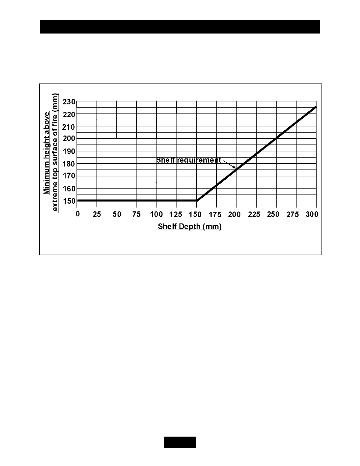
2.8 The minimum height from the extreme top surface of the fire to the underside
of a shelf or other projection made of wood or any other combustible material is
shown in graph 1.
2.9 There is no restriction on the depth of non-combustible projections but a space
of at least 30mm should be allowed above the top of the appliance to enable removal
of the case front.
2.10 It is advisable that combustible fabrics such as curtains are not fitted above the
fire. If, however, this is unavoidable, a clearance of at least 150mm must be
maintained from the extreme bottom edge of the fabric to the extreme top surface of
the fire.
2.11 The appliance can be installed with or without a non-combustible hearth. If a
non-combustible hearth is installed, there must be a minimum clearance from the
top surface of the hearth to the absolute bottom of the appliance of 18mm (see figure
1). The hearth must be at least 700mm wide x 300mm deep. The non-combustible
hearth material must be at least 12mm thick. Its top surface should be preferably
50mm above floor level to discourage the placing of carpets or rugs over it.
If the appliance is not installed with a hearth meeting the above conditions, the
minimum distance from the top surface of the finished floor covering (including any
carpet etc.) to the absolute bottom of the appliance must be at least 40mm (see
figure 1).
2.12 A hole 152mm (6in) is required through the wall for the flue unit.
Graph 1. Combustible shelf clearances.
INSTALLER’S GUIDE
Page 8
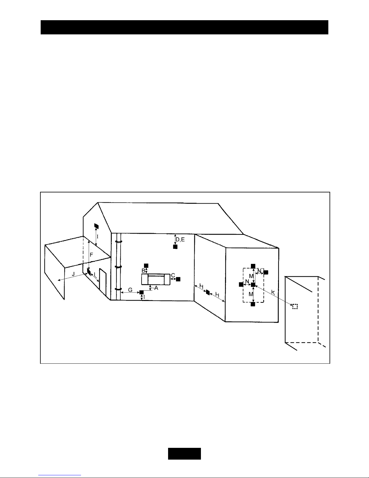
Figure 2 Terminal Positions
The minimum height of the hole centre is shown in figure 1 and on the wall fixing
template.
2.13 Minimum allowable distances from the terminal are shown in table 1 and
figure 2: -
2.14 In England and Wales the Building Regulations require a terminal guard to be
fitted if the terminal could come into contact with people near the building or be
subject to damage.
Fitting a terminal guard is recommended where contact with or damage to the
terminal is possible even if regulations do not demand it.
A suitable guard is supplied with this fire.
2.15 No special ventilation bricks or vents into the room containing the appliance
are required.
INSTALLER’S GUIDE
Page 9
Table 1.
Dimension
(See figure 2)
Terminal Position Minimum
Distance
A* Directly below an opening, air brick, opening
window etc.
300mm
B* Above an opening, air brick, opening window etc. 300mm
C* Horizontally to an opening, air brick, opening
window etc.
300mm
D Below gutters, soil pipes or drain pipes 300mm
E Below eaves 300mm
F Below balconies or car port roof 600mm
G From a vertical drain pipe or soil pipe 300mm
H From an internal or external corner 600mm
I Above ground, roof or balcony level 300mm
J From a surface facing the terminal 600mm
K From a terminal facing the terminal 600mm
L From an opening in a car port (e.g. door, window)
into dwelling
1200mm
M Vertically from a terminal on the same wall 1500mm
N Horizontally from a terminal on the same wall 300mm
O From the wall on which the terminal is mounted N/A
P From a vertical structure on the roof N/A
Q Above intersection with roof N/A
*In addition, the terminal should not be nearer than 300mm to an opening in the
building fabric formed for the purpose of accommodating a built-in element such as
a window frame or door frame. See figure 3.
 Loading...