

Page 1
600B206/02
MODEL BR417
(G.C.32-032-07)
Inset Live Fuel Effect
Gas Fire
with
Ultimate
or
Superflame
Front
INSTALLER GUIDE
Please keep in a safe place for future reference
Page 2

2
This Installer Guide gives sufficient details to enable the appliance to be
installed and maintained. If further information is required, our Valor
AdviceLine will be pleased to help.
Please telephone 0345 626341 (Local call rates apply)
As supplied, this appliance is for use with natural
gas (G20)
When converted using Valor conversion kit no.
591149 this appliance is for use with propane gas
(G31)
These appliances are for use in the United
Kingdom (GB) and the Republic of Ireland (IE) only.
As supplied, this appliance is for use with natural
CUSTOMER CARE
Please leave this Installer Guide with the user
Page 3

3
CONTENTS
Page
Appliance data 3
General installation requirements 3
Pack contents 6
Preliminary checks 7
• Ignition spark check 7
• Fireplace check 7
• Flue pull check 7
Gas supply connection 7
Preparing appliance for installation 8
Convection box installation 9
• Front fixing 9
• Cable retention 9
• Floor front sealing 11
Burner, surround & supply pipe installation 11
• Preliminary burner checks 11
• Reference pressure check 11
Ceramic coals & walls installation 12
Full operating checks 13
• Control settings check 13
• Flue spillage check 13
• Flame supervision & spillage monitoring system check 13
Final review 14
Servicing & parts replacement 15
• Burner plaque replacement 15
• Front surround removal 15
• Burner unit removal 16
• Pilot unit removal 16
• Gas tap removal 16
• Piezo generator removal 16
• Greasing gas tap 16
• Injector removal 16
• Removing appliance from fireplace 16
• Short list of spares 17
Page 4
4
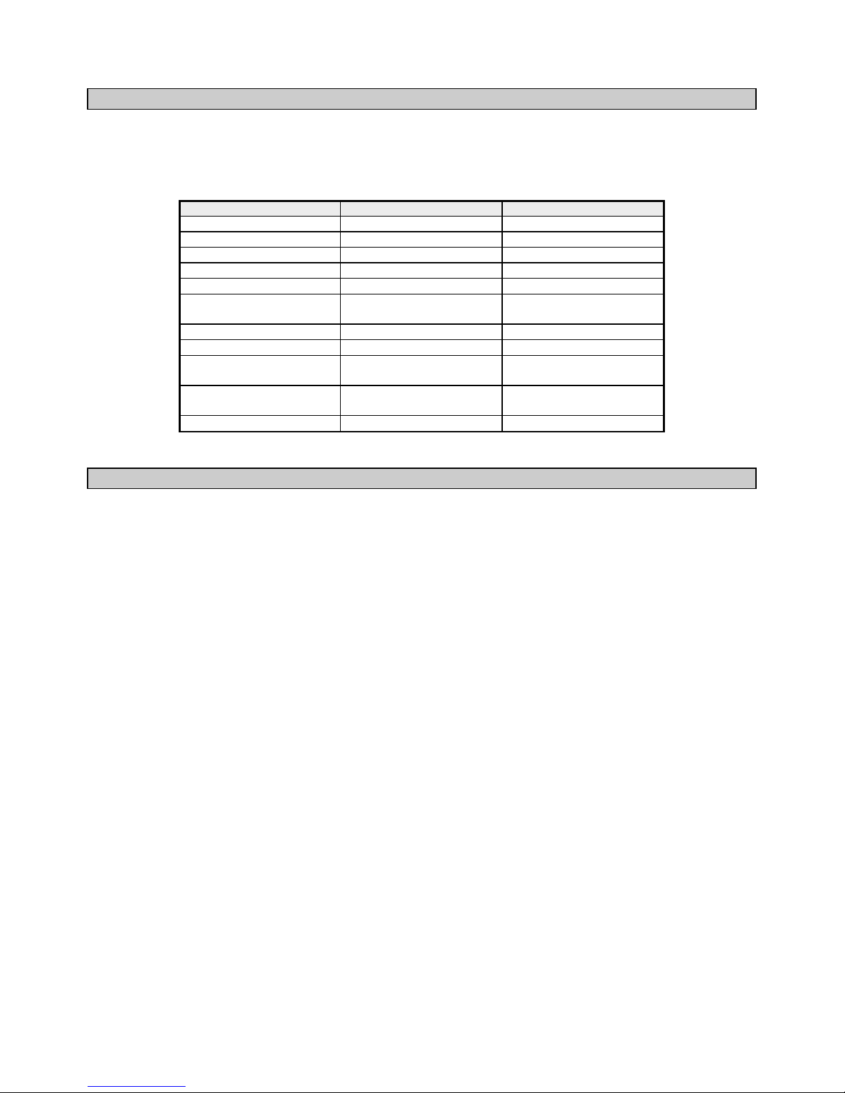
1. APPLIANCE DATA
This product uses fuel effect pieces. It makes sense to take
care when handling these articles to ensure that the release
of dust is kept to a minimum.
This appliance does not contain any component
manufactured from asbestos or asbestos related products.
The appliance data label is on a plastic tie below the burner
and is visible when the bottom front cover is removed.
Gas Natural (G20) Propane (G31)*
Inlet Pressure 20mbar 37mbar
Input - Max. (Gross) 6.0kW (20,500Btu/h) 6.1kW (20,800Btu/h)
Input - Min. (Gross) 2.2kW (7500Btu/h) 3.6kW (12280Btu/h)
Output - Max. 3.5kW (11,900Btu/h) 3.6kW (12,280Btu/h)
Output - Min 1.1kW (3750Btu/h) 1.8kW (6140Btu/h)
Burner Test Pressure (Cold) 17.0±0.75mbar (6.8±0.3in
w.g.)
35.6±0.75mbar
(14.3±0.3in w.g.)
Gas Connection 8mm pipe 8mm pipe
Burner Injector Bray Cat. 18 Size 360 Bray Cat. 18 Size 170
Pilot & Atmosphere Sensing
Device
SIT Ref. OP9030 SIT Ref. OPLPG9222
Ignition Piezo Electric. Integral with
Gas Tap
Piezo Electric. Integral with
Gas Tap
Aeration Non-adjustable Non-adjustable
* When converted using Kit 591149
2 GENERAL INSTALLATION REQUIREMENTS
2.1 For the user’s protection, in the United Kingdom
it is the law that all gas appliances are installed by
competent persons in accordance with the current
edition of the Gas Safety (Installation and Use)
Regulations. Failure to install the appliance
correctly could lead to prosecution. The Council
for the Registration of Gas Installers (CORGI)
requires its members to work to recognised
standards.
The Confederation for the Registration of Gas
Installers (CORGI) requires its members to work
to recognised standards.
The installation must be in accordance with these
instructions.
In the United Kingdom the installation must also
be in accordance with:
a) All the relevant parts of local regulations.
b) The current edition of the Building
Regulations issued by the Department of the
Environment and the Welsh Office or the
Building Standards (Scotland)
(Consolidation) Regulations issued by the
Scottish Development Department.
c) All relevant codes of practice.
d) The relevant parts of the current editions of
the following British Standards:BS 715
BS 1251
BS 1289 Part 1
BS 1289 Part 2
BS 4543 Part 2
BS 5440 Part 1
BS 5440 Part 2
BS 5871 Part 2
BS 6461 Part 1
BS 6891
BS 8303
In the republic of Ireland the installation must
also conform to the relevant parts of:
a) The current editions of:-
IS 813
ICP3
IS327
All relevant national and local rules in force.
2.2 In the United Kingdom, as supplied, this
appliance can be installed in the following
situations: -
2.2.1 To a fireplace complete with surround and hearth
complying with B.S 1251. The required fireplace,
hearth, debris catchment area and clearance
dimensions are shown in figure 1a.
2.2.2 To a fireplace incorporating a twin walled metal
flue box complying with the constructional
requirements of the current edition of BS 715 and
standing on a non-combustible base. The
dimensions of the flue box must conform to the
opening shown in figure 1b. For flue details see
sections 2.3 & 2.4.
Page 5

5
2.2.3 To a fireplace that has a precast concrete or clay
flue block system conforming to BS1289. The
appliance is suitable for installations conforming
to older versions of BS1289 as well as the current
edition. The flue blocks must have a minimum
width not less than 63mm and a cross-sectional
area not less than 13,000mm
2
.
Older editions of
BS1289 required a cross-sectional area of
13,000mm2. The current revision of the standard
requires 16,500mm2. This appliance is suitable in
both cases. The total depth of the opening
measured from the finished front of the fireplace
(Including plaster, surround etc) must be not less
than 100mm.
The current version of BS1289 recommends that
there should be an air space or insulation between
the flue blocks and the plaster because heat
transfer may cause cracking on directly plastered
flues. However, generally this appliance is suitable
for installations under all circumstances unless
there is a history of cracking problems.
Remember that faults such as cracking may be
caused by poorly built and restrictive flues, e.g.
mortar extrusions, too many bends, flue heights
below three metres, restrictive terminations, etc.
2.2.4 To a builder’s opening within the dimensions
shown in figure 1a.
2.3 Suitable flues and minimum flue sizes are as
follows: a. 225mm x 225mm conventional brick flue.
b. 175mm diameter lined brick or stone flue.
c. 200mm diameter factory made insulated flue
manufactured to BS 4543.
d. 175mm diameter flue pipe (see B.S 6461 part 1
for suitable materials).
e. Single wall, twin wall or flexible flue liner of
minimum diameter 125mm. The materials to
be used are stainless steel or aluminium as
specified in B.S 715.
f. A properly constructed precast concrete or
clay flue system conforming to BS 1289 Part 1
or 2.
It should be noted that, sharp bends or
horizontal runs in metal flues at the top of the
system could be a cause of problems in these
types of installation.
2.4 The minimum effective height of the flue must be
3m.
2.5 The flue must not be used for any other appliance
or application.
2.6 Any chimney dampers or restrictors should be
removed. If removal is not possible they must be
fixed in the open position.
2.7 If the appliance is intended to be installed to a
chimney which was previously used for solid fuel,
the flue must be swept clean prior to installation.
All flues should be inspected for soundness and
freedom from blockages.
2.8 If the fireplace opening is of underfloor draught
type, it must be sealed to stop any draughts.
2.9 The appliance must be mounted behind a non-
combustible hearth (n.b conglomerate marble
hearths are considered as non-combustible). The
appliance can be fitted to a purpose made
proprietary class “O” 150°C surround. The
hearth material must be at least 12mm thick. The
periphery of the hearth (or fender) should be at
least 50mm above floor level to discourage the
placing of carpets or rugs over it.
The surface of the hearth must be sufficiently flat
to enable the bottom of the front surround, the
burner bracket and the bottom front cover casting
to be aligned horizontally. Any excessive
unevenness (uneven tiles, Cotswold stone, etc.)
should be rectified.
The appliance must not stand on combustible
materials or carpets.
The appliance must not be fitted directly against a
combustible wall. If the appliance is to be fitted
against a wall with combustible cladding, the
cladding must be removed from the area covered
by the outer surround (see figure 1c). We suggest
that the actual surround is used as a template to
mark the area for combustible cladding removal.
2.10 The minimum allowable distance to a corner wall
from the outside edge at either side of the front
surround is 178mm.
2.11 The front face of the fireplace should be
reasonably flat over the area covered by the
convection box top and side flange seals to ensure
good sealing. These faces should be made good if
necessary.
The fireplace floor should be reasonably flat to
ensure that a good seal with the convection box
can be made (see fig.15).
2.12 The minimum height from the top surface of the
hearth to the underside of any shelf made from
wood or other combustible materials is as follows:
-
• For a shelf up to 150mm deep
Minimum height = 750mm.
• For a shelf deeper than 150mm
Minimum height = 750mm + 12.5mm for every
25mm depth over 150mm.
2.13 Note that soft wall coverings (e.g. embossed vinyl,
etc.) are easily affected by heat. They may scorch
or become discoloured when close to a heating
appliance. Please bear this in mind when
installing.
2.14 The appliance must not be installed in any room,
which contains a bath, or shower or where steam
is regularly present.
2.15 An extractor fan may only be used in the same
room as this appliance, or in any area from which
ventilation for the appliance is taken, if it does not
affect the safe performance of the appliance. Note
the spillage test requirements detailed further on
in this manual. If the fan is likely to affect the
appliance, the appliance must not be installed
unless the fan is permanently disconnected.
2.16 In the United Kingdom (GB) no special
ventilation bricks or vents are required in the
room for this appliance.
In the Republic of Ireland (IE), permanent
ventilation must comply with the regulations
currently in force.
Page 6

6
Fig 2 Pack contents
2.17 Propane gas appliances must not be installed in a
room, which is built entirely below ground level
(see BS 5871 Part 2).
.
3. UNPACKING
The pack contains:
1 Burner & Convection box Unit
1 Front surround unit
1 Nut & olive for 8mm inlet pipe
1 Ceramic back wall
1 Pair of ceramic side walls
1 Front base coal- left & right halves
1 Rear base coal
1 Pack of 5 loose coals
2 Small “U” seals for convection box side flanges
1 Strip of floor sealing tape
1 Flue restrictor plate
6 Fibre plugs
4 Woodscrews
2 Fire retaining cables
2 Cable clamps
4 Eyebolts
1 Installation template
1 Smoke match tube
1 Fire front casting
1 Bottom front cover casting
1 Literature pack
Carefully remove the contents. Take special care in handling
the ceramic walls and the coals.
Check that all the listed parts are present and in good
condition.
Fig. 1 Installation Data
(a) Fireplace Dimensions
** Does not apply to pre-cast flues
–
(b) Twin walled metal flue box
(Internal dimensions)
* If internal width is greater than 440mm,
the opening width must be reduced to
not more than 440mm to ensure
adequate sealing to fire.
Page 7
7
4. PRELIMINARY CHECKS
4.1 CHECK IGNITION SPARK
Before attempting to install, it is worth checking that the
piezo electric spark ignition system operates satisfactorily.
To initiate the spark, depress the control knob and while
keeping it depressed, turn anticlockwise through
approximately 60° to the “PILOT/IGN” position. A spark
should track from the electrode pin to the thermocouple
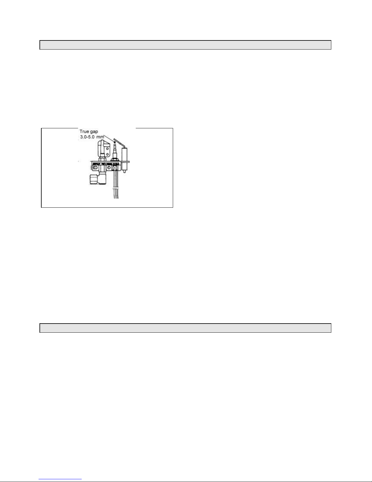
tip. If there is no spark or incorrect tracking, check the
spark gap between the electrode wire and thermocouple tip
(see figure 3). If the spark gap is correct, check the ignition
wiring.
4.2 CHECK THE FIREPLACE
The fireplace must comply with all the requirements of
section 2.
4.2.1 Fireplace general condition
The fireplace floor should be reasonably flat to ensure that
the convection box can be installed without it rocking and so
that a good seal can be made at the bottom front of the box.
The front face of the fireplace should be reasonably flat over
the area covered by the convection box top and side flange
seals to ensure good sealing. These faces should be made
good if necessary. If the appliance is to be fitted against a
wall with combustible cladding, the cladding must be
removed from the area covered by the outer surround (see
figure 1c). We suggest that the actual surround is used as a
template to mark the area for combustible cladding removal.
4.2.2 Soundness for appliance attachment
Two primary methods of retaining the appliance are
provided: -
1) By fixing to the fireplace front.
2) Using concealed tension cables fixed to the rear of the
fireplace opening together with secondary fixing to the
fireplace floor.
The methods are detailed in section 7 of this manual.
Before selecting the retention method, consult with the
customer. Method 2 is provided for instances where drilling
holes in the front surface of the fireplace surround is
unacceptable to the customer or otherwise impractical. N.B.
It is unwise to attempt to drill into marble without the
proper tools and equipment.
If method 1 is chosen, make sure that the fireplace front
surround area is sound enough to take the rawlplugs and
woodscrews. If necessary, make sound with a suitable
cement.
If method 2 is chosen, make sure that the areas at the back
and towards the centre of the fireplace floor are sound
enough to take the eyebolts and screws. If these areas have
deteriorated due to prolonged use, they should be made
sound with a suitable cement.
4.2.3 Installations using a metal flue box
The whole of the top surface of the metal flue box must be
covered with a layer of mineral wool or equivalent insulation
at least 100mm thick (see figure 1b).
4.3 FIREPLACE FLUE PULL
After preparing the fireplace, carry out the flue flow test as
detailed in BS5440: Part 1.
Note - A 13 gramme smoke pellet will generate the required
volume of smoke, anything smaller may give a false pass result.
Observe the smoke. If there is a definite flow into the
opening continue with the installation. If there is not a
definite flow, preheat the chimney for ten minutes and
recheck. If there is still no definite flow, the chimney may
need attention. Do not fit the appliance. Seek expert advice.
5. GAS SUPPLY CONNECTION
A nut and olive are provided for an 8mm pipe inlet
connection to the elbow at the bottom front of the
appliance. The elbow can be rotated to allow a connection
from any direction. The elbow includes a valve for isolating
the gas supply.
The supply pipe must be rigid material. Flexible pipe must
not be used.
5.1 CONCEALED SUPPLY PIPE
CONNECTION
If a concealed connection from inside the fireplace is
required then, before the appliance is fitted into the
fireplace it will be necessary to extend the supply line so
that it will project through the sealed opening at the back of
the convection box (near the left side) and run to the elbow
at the front
The pipe run from the supply line up to the rear opening in
the convection box must be kept clear of the area which will
be taken by the convection box when it is installed. A
template is supplied to aid the installation of the pipe run.
We recommend the following method for installing with a
concealed supply pipe:
5.1.1 Cut the template to the shape shown by the “Debris
catchment area”. Note that the areas are different for
fireplaces with conventional brick flues and precast flues.
5.1.2 Place the template on the fireplace floor (printed
side upward) with the front line level with the front surface
of the fireplace. The centre line of the template should line
up with the centre of the fireplace. Tape the template
securely in this position
5.1.3 Make sure that the fireplace is clear of all material
over the full area covered by the template including that
marked “Debris catchment area”.
Fig. 3 Pilot
Page 8
8
5.1.4 Install the supply pipe to run through the thick line
marked “Supply pipe entry” and up to the inlet elbow
position.
Note that the centre of the appliance inlet elbow is 18mm
above the fireplace floor. The inlet elbow should be
removed from the appliance and fitted to the supply pipe at
this stage.
Remove the template. Note: If the supply pipe connection is to
be from the right side, keep the template, It will be useful for
bending the pipe later on (Section 8.4)
5.2 SIDE SUPPLY PIPE CONNECTION
The appliance is designed to allow a side supply pipe to run
in front of the front surround and through a cut- out at
either rear bottom corner of the fire front casting. For side
connection, final installation of the supply pipe should be
left until the appliance is installed in the fireplace.
6. PREPARING APPLIANCE FOR
INSTALLATION
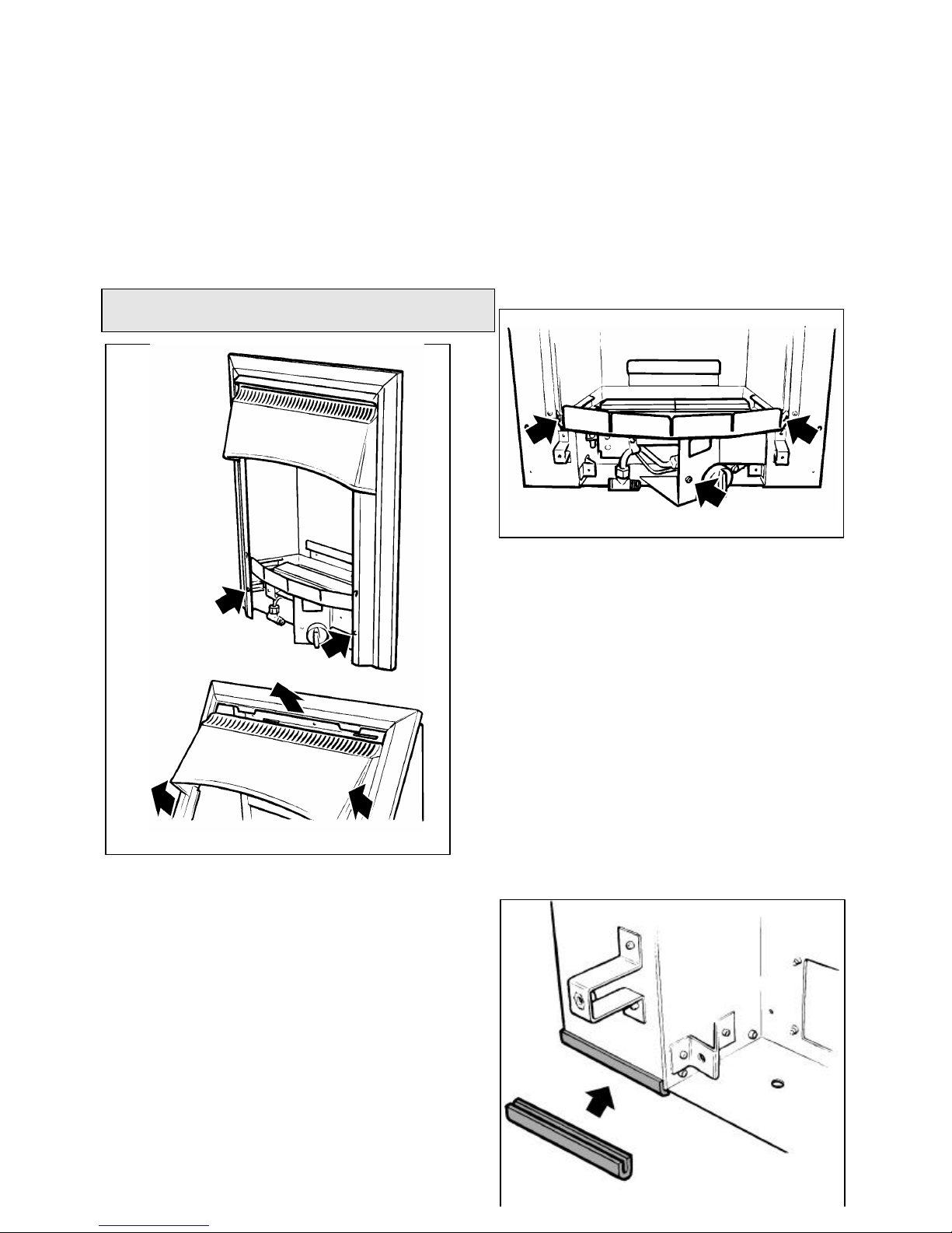
6.1 Remove the two screws securing the bottom of
the front surround to the sides of the convection box.
Raise the front surround to allow the retaining lugs at the
top to clear the slots in the convection box hood and then
lift clear (see figure 4).
6.2 Detach the burner unit from the convection box
by removing three screws (see figure 5). Lift the burner unit
clear.
6.3 Fit the two small "U" section seals to the bottom
edges of the convection box side flanges (see fig.6)
Fig. 4 Front surround removal
Fig. 5 Burner attachment points
Fig. 6 “U” seal positions
Page 9
9
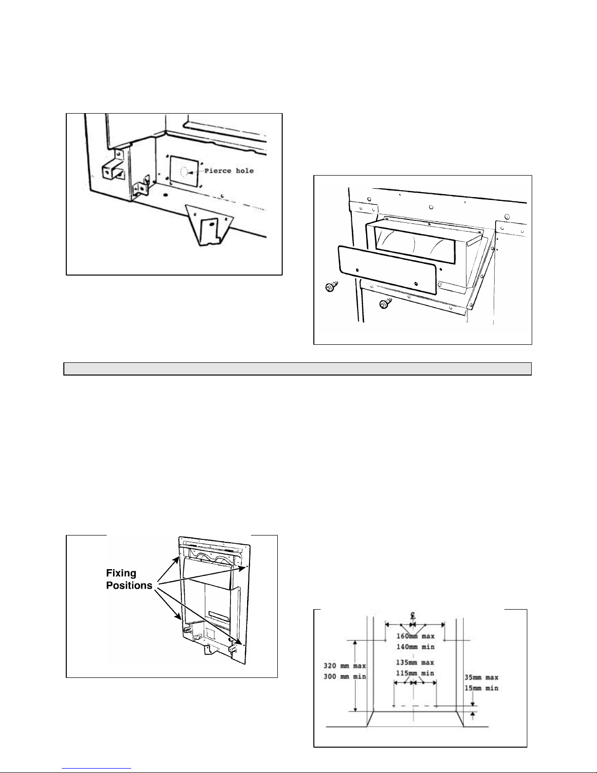
6.4 For concealed connection only
Pierce a hole in the seal at the back of the convection box
(see figure 7). The seal must envelop the pipe. If the hole is
larger than the pipe, seal it with tape. Do not pierce the seal
unless the supply pipe is to pass through it.
6.5 The flue restrictor
This appliance is supplied with a flue restrictor for use
where the flue draught is excessive. The restrictor must
NOT be fitted where a precast flue or a flue liner is used.
For all other installations the restrictor should be fitted.
There may however, be certain exceptional circumstances
where fitting the restrictor causes the fire to fail the spillage
test. In such cases the restrictor will have to be removed.
After removal conduct the spillage check again.
The restrictor is packed loose with the appliance and is
fixed with two screws (See figure 8).
7. CONVECTION BOX INSTALLATION
7.1 METHOD (1) - FRONT FIXING TO
FIREPLACE SURROUND
Make sure that the fireplace front surround area is sound
enough to take the rawlplugs and woodscrews. If necessary,
make sound with a suitable cement.
7.1.1 Place the convection box centrally in the fireplace in
the position in which it is to be permanently installed.
If a concealed connection is being used, insert the
convection box into the fireplace feeding the supply pipe
through the pierced hole in the rear seal.
7.1.2 Mark the fireplace front surround through the four
fixing holes in the side flanges of the convection box (see
figure 9).
7.1.3 Remove the convection box. Drill four holes in the
fireplace front surround at the marked positions using a
no.12 masonry drill.
7.1.4 Insert a rawlplug into each hole.
7.1.5 Place the convection box back in position in the
fireplace.
7.1.6 Fit a woodscrew through each hole in the
convection box flanges and tighten to seal the box to the
fireplace surround.
7.2 METHOD 2 - CABLE RETENTION
AND FLOOR FIXING
Make sure that the areas at the back and towards the
centre of the fireplace floor are sound enough to take the
eyebolts and screws. If these areas have deteriorated due to
prolonged use, they should be made sound with a suitable
cement.
7.2.1 Drill four holes in the rear wall of the fireplace for
the eyebolt plugs. The holes should be drilled within the
range of positions shown in figure 10 using a no.12
masonry drill. The holes should be equidistant each side of
the centre line of the fireplace to ensure that the appliance
finishes centrally in the opening when tension is applied to
the cables.
Fig. 7 Concealed connection seal piercing
Fig. 8 Flue restrictor
Fig. 9 Front fixing
Fig. 10 Eyebolt positions
Page 10

10
Page 11
11
7. 2.2Insert a fibre plug into each hole. Use the rawlplugs
supplied with this appliance - Never use plastic plugs instead
of the fibre plugs supplied. Screw the eyebolts into the plugs.
Make sure that the bolts are secure.
7. 2.3Place the convection box unit close to the fireplace
but allow sufficient access into the fireplace opening so that
the cables can be threaded through the eyebolts and
returned through the back of the convection box.
If a concealed connection is being used, insert the
convection box into the fireplace feeding the supply pipe
through the pierced hole in the rear seal.
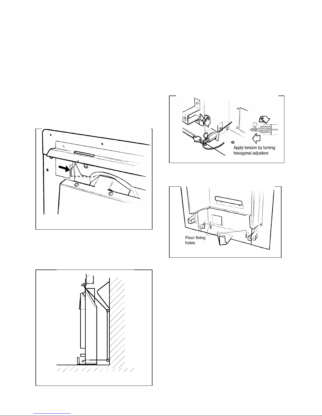
7.2.4 The convection box has two holes at each side of the
convected air opening. Insert one end of each cable (one
cable each side) from the back through the lower of the two
holes and return the end through the upper of the holes
(see figure 11). Give the cables a pull so that they grip
against the convection box flanges.
7.2.5 Thread the cables through the upper eyebolts in the
rear wall and then through the lower eyebolts. Return the
cables through the holes near the bottom of the convection
box back panel and through the “V” shaped brackets near
the bottom front sides of the convection box (see figure
12).
7.2.6 Place the convection box fully back into the fireplace
opening so that it is sealed against the fireplace front
surround.
7.2.7 Fit a cable retainer over the bottom end of each
cable.
7.2.8 Pull each cable taut. Push the cable retainers hard
up against the “V” brackets. Tighten the screws in the
retainers so that they clamp the cables in position. Apply
tension to the cables by turning the hexagonal adjusters by
hand (see figure 13).
7.2.9 Drill a hole into the fireplace floor through each of
the two holes in the base of the convection box using a
no.12 masonry drill (see figure 14).
7.2.10 Insert a fibre plug into each hole. Use the
rawlplugs supplied with this appliance - Never use plastic
plugs instead of the fibre plugs supplied. Fit a woodscrew in
each plug and tighten.
7.2.11 Inspect the installation of the convection box
against the fireplace surround. If the convection box is
aligned squarely and the sealing is satisfactory, fully tighten
the cable retainers.
7.2.12 If the convection box is not correctly aligned,
release the tension on the cables by slackening the screws
and turning the hexagonal adjusters fully anticlockwise.
The convection box should then automatically realign itself.
Pull each cable taut again and push the cable retainers back
against the “V” brackets. Again, tighten the screws in the
retainers and apply tension to the cables by turning the
hexagonal adjusters clockwise as far as possible.
7.2.13 Push the free length of the cables inside the
convection box so that they are available to allow easy
removal and refitting of the appliance during subsequent
service calls.
Fig. 11 Upper cable retaining
Fig. 12 Cable route
Fig. 13 Lower cable retaining
Fig. 14 Floor fixings
Page 12
12
7.3 SEAL THE FLOOR FRONT
(ALL INSTALLATIONS)
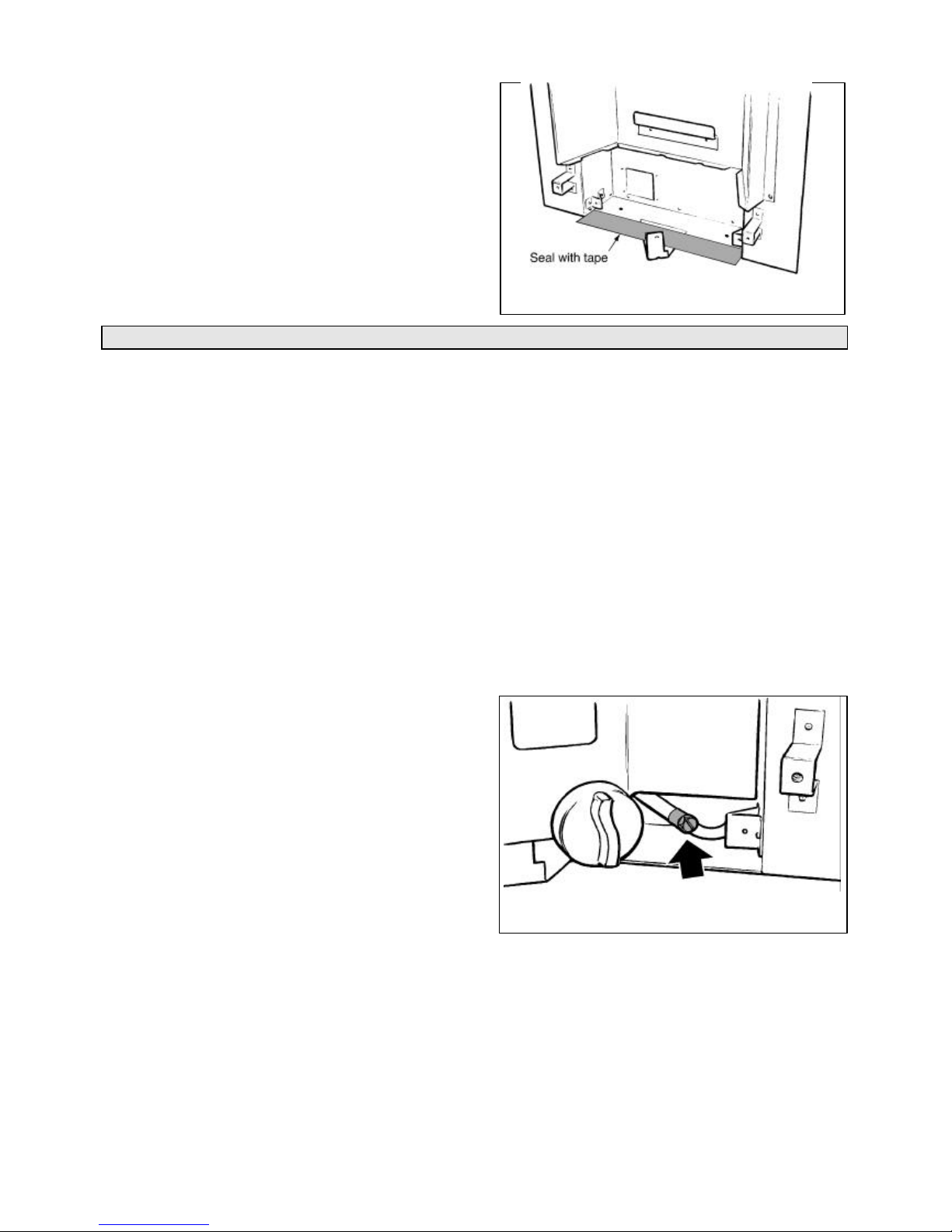
Using the floor sealing tape supplied, seal the bottom of
the convection box to the fireplace and hearth floor. Run
the tape over the burner fixing bracket. (See figure 15).
8. BURNER, FRONT SURROUND & SUPPLY PIPE INSTALLATION
8.1 Refit the burner unit to the convection box with
three screws.
8.2 Locate the two lugs at the top of the front
surround in the slots in the convection box hood. Swing the
bottom of the surround sides back against the convection
box and lower the surround so that the lugs are fully seated
in the slots in the convection box hood.
8.3 Refit the two screws to secure the surround
sides to the convection box brackets.
8.4 Connect the supply line to the appliance.
For right hand side connection. The supply pipe will have to
be formed to go behind the control knob and burner
support bracket. The installation template contains a
diagram for bending this supply pipe.
8.5 Pressure check the installation pipework for gas
soundness in accordance with the current edition of
BS6891. A long brush may be required to reach some joints.
8.6 PRELIMINARY BURNER CHECKS
Some burner operations can be checked at this stage.
Checking now will mean that less disassembly will be
required if any problems are found. A full check should still
be made, however, after final installation.
8.6.1 If closed, open the isolating valve at the inlet elbow.
8.6.2 Depress the control knob and turn anticlockwise
partially towards the “PILOT/IGN” position until some
resistance is felt. Keep depressed at this position to purge
air from the system then, while keeping it depressed, turn
fully to the “PILOT/IGN” position. A spark should be
generated at the pilot while turning. The spark should
ignite the pilot.
8.6.3 When pilot ignition has been achieved, keep the
control knob depressed for approximately ten seconds to
allow the thermocouple probe to warm up and then release
it. If the pilot does not remain alight, ensure that the air
has been purged, that the pilot orifice is clear and that the
thermocouple connections are sound. Replace the pilot
unit if necessary (see servicing section of this manual).
8.6.4 When the pilot is alight and stable, partially depress
the knob and turn to “LOW”. The pilot should then light
the main burner at its low setting. There may be a delay of
up to four seconds between the pilot lighting and ignition
of the gas at the main burner. This is normal and is due to
the time required to fill the main burner compartment with
sufficient gas for ignition.
8.6.5 When the burner is operating properly, partially
depress the control knob and gradually turn it anti-
clockwise. The burner flames should gradually increase
until the knob reaches the “HIGH” position. When the
above checks have been completed partially depress the control
knob and turn to “OFF”.
8.6.6 If the above checks are satisfactory, continue with
the installation. If not, check the control and ignition
circuitry and components as described in the servicing
section of this manual.
8.7 CHECK REFERENCE PRESSURE
The appliance is pre-set to give the correct heat input at the
inlet pressure shown in section 1 of this manual. No
adjustment is necessary. Check the burner pressure by
fitting a pressure gauge at the test point. The test point is
on the pipe situated below the bottom right corner of the
burner unit (See figure 16). Check the pressure with the
appliance alight and set at maximum output.
After checking, turn off the appliance. Remove the
pressure gauge and replace the test point sealing screw.
Relight the appliance. Turn to the maximum output
position and test around the sealing screw for gas
soundness with a suitable leak detection fluid.
Fig. 15 Floor sealing
Fig. 16 Pressure test point
Page 13
13
9. CERAMIC COALS & WALLS INSTALLATION
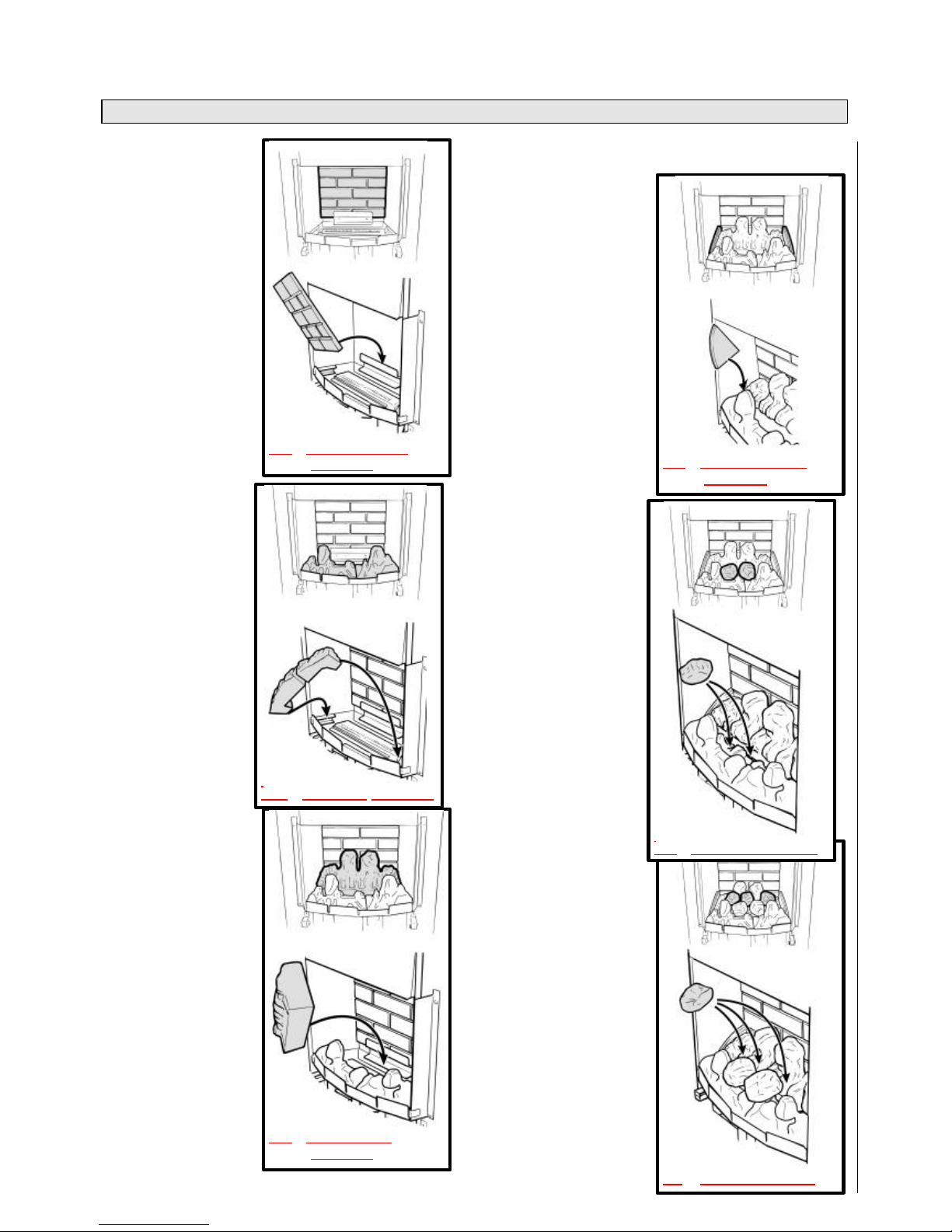
9.1 With its
feather edge at the top,
place the ceramic rear
wall into the channel at
the back of the fire box.
Push the wall flat against
the rear of the fire box.
(See figure 17).
9.2 Place the two
halves of the front base
coal in the burner
compartment so that
they rest on the ledges
at the sides and front.
Pull the coals forward so
that they are
immediately behind the
front rim of the burner
compartment (See fig.
18).
9.3 Place the rear
base coal in the burner
compartment behind the
front coal. Its rear face
should touch the rear
ceramic wall (See figure
19).
9.4 The ceramic
side walls are marked at
the rear bottom corners
“L” (Left side) & “R”
(Right side). Place the
side walls against the
sides of the fire box and
in the recesses at the
sides of the base coals.
The markings “L” & “R”
should be at the back
bottom corners and
facing to the centre of the
back of the firebox (See
figure 20).
9.5 Install the 5
loose coals as follows.
The smooth surfaces of
the coals should be at
the bottom and back.
9.5.1 Select the two
largest coals. Place them
in the central two valleys
of the front coal (See
figure 21).
9.5.2 Place the three
remaining coals behind
and approximately
midway between each of
the coals in the front row
(See figure 22).
Fig 22 Middle row of coals
Fig. 21 Front row inner coals
Fig. 19 Rear base coal
installation
Fig. 18 Front coal installation
Fig. 17 Ceramic rear wall
installation
Fig. 20 Ceramic side walls
installation
Page 14
14
10. FULL OPERATING CHECKS
10.1 RECHECK CONTROL SETTINGS
Now that all the ceramic fuel effects are in position, the
control operation must be fully rechecked.
10.1.1 Make sure that the isolating valve at the inlet
elbow is open.
10.1.2 Depress the control knob and turn
anticlockwise partially towards the “PILOT/IGN” position
until some resistance is felt. Keep depressed at this
position to purge air from the system then, while keeping it
depressed, turn fully to the “PILOT/IGN” position. A
spark should be generated at the pilot while turning. The
spark should ignite the pilot.
10.1.3 When pilot ignition has been achieved, keep
the control knob depressed for approximately ten seconds
to allow the thermocouple probe to warm up and then
release it. If the pilot does not remain alight, ensure that
the pilot orifice is clear.
10.1.4 When the pilot is alight and stable, partially
depress the knob and turn to “LOW”. The pilot should
then light the main burner at its low setting. There may be a
delay of up to four seconds between the pilot lighting and
ignition of the gas at the main burner. This is normal and
is due to the time required to fill the main burner
compartment with sufficient gas for ignition.
10.1.5 When the burner is operating properly,
partially depress the knob and gradually turn it anticlockwise. The burner flames should gradually increase
until the knob reaches the “HIGH” position.
10.1.6 Partially depress the control knob and turn
back to “PILOT/IGN”. The main burner flames should be
extinguished but the pilot should remain alight.
10.1.7 Partially depress the control knob and turn
to “OFF”. The pilot should be extinguished.
10.2 CHECK FOR SPILLAGE
A spillage check must be made before leaving the installed
appliance with the customer. Make this check with the appliance
fully installed with the ceramic fuel effects and front surround in
position.
10.2.1 Close all doors and windows in the room
containing the appliance.
10.2.2 Light the appliance and turn the control
knob to “HIGH”
10.2.3 Leave the appliance on for five minutes.
10.2.4 Place the smoke match tube into the convection box
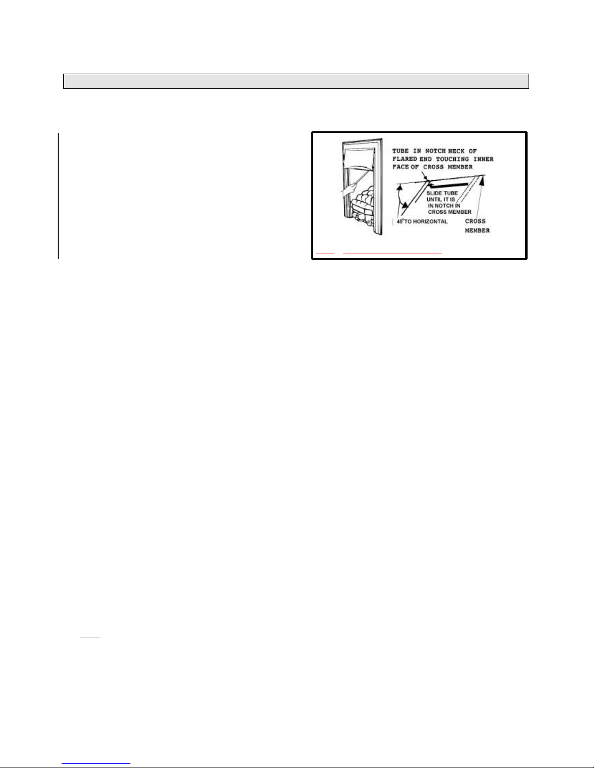
at the right hand side and immediately below the black top
cross member. Angle it at approximately 45° to the
horizontal.
Insert the tube so that the neck of its flared end touches
the inside surface of the edge of the cross member (figure
23).
Keeping the neck of flared end in contact with the edge of
the cross member, slide the tube to the left until you feel it
enter the notch in the edge of the cross member. Make
sure that the tube is pointed upwards at 45º to the
horizontal.
The installation is satisfactory if the smoke is drawn into
the appliance. If the smoke is not drawn into the appliance,
leave the appliance alight at the maximum setting for a
further ten minutes and then repeat the test. If the smoke
is still not drawn into the appliance, inspect the sealing to
the fireplace surround. If the sealing is satisfactory but the
appliance is installed with the flue restrictor (see section
6.5), remove the restrictor, reseal the appliance and retest.
If smoke is still not drawn into the appliance disconnect the
appliance and seek expert advice.
10.2.5 If the above test is satisfactory, open all
internal connecting doors, hatches, etc. in the room. Keep
all doors and windows that open to the outside of the
building closed. Recheck for spillage as above. If an
extractor fan is installed in the same room as the appliance
or a connecting room, check that spillage does not occur
with the fan operating and all doors and other openings
between the fan and the appliance open.
If the smoke is drawn into the appliance, continue with the
installation. If the test is not satisfactory, disconnect the
appliance and advise the customer of the cause of failure.
10.3 FLAME SUPERVISION & SPILLAGE
MONITORING SYSTEM
This pilot unit incorporates a system which will
automatically shut off the gas supply if the pilot flame goes
out or if there is insufficient oxygen due to spillage or lack
of ventilation.
Check that the system operates properly as follows;
10.3.1 Light the appliance. Set at the “HIGH”
position and leave for one minute.
10.3.2 Turn back to “OFF” to extinguish the pilot.
Note the time when the pilot goes out. Listen for a snap sound
at the gas tap. Note the time when the sound is heard. This
sound is caused by an electromagnetic valve shutting off the
gas supply through the tap. The valve is located in the body
of the tap. The valve should operate within 60 seconds of the
pilot going out. If the valve does not operate within this time
limit do not allow the appliance to be used until the fault
has been corrected.
This monitoring system must not be adjusted, bypassed or put out
of operation.
This monitoring system, or any of its parts, must only be
exchanged using Valor authorised parts.
Fig. 23 Smoke match tube position
Page 15
15
11. FINAL REVIEW
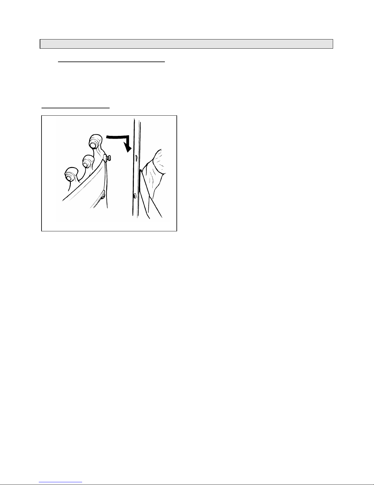
11.1 All models except black & chrome front casting: Fit
the fire front casting to the front surround. Locate the two
screw heads at the rear top corners of the casting through
the keyhole slots at the inner sides of the surround. If the
screw heads do not project enough or project too far, the
screws can be adjusted. Lower the casting so that it rests on
the hearth (see figure 24).
Black & chrome front casting: Place the fire front casting in
front of the appliance.
11.2 Place the bottom front cover casting in position
below the fire front casting.
11.3 Visually inspect the appliance. Clean off any marks
incurred during installation.
11.4 Hand these instructions and the user's instructions
to the customer.
11.5 Advise the customer how to operate the appliance.
Point out that lighting instruction details are on a tie at the
bottom of the appliance.
11.6 Explain to the customer that the appliance has a
flame failure & spillage monitoring system. Point out the
explanation of this system shown in the owner’s guide
under “Operating the fire”.
Advise that if the fire goes out for any reason, wait at least
three minutes before relighting.
Stress that if the monitoring system repeatedly shuts off
the fire, the appliance should be switched off and a
specialist should be consulted.
11.7 Advise the customer that they should read their
Owner’s guide before operating the fire and always follow
the advice in the section headed “Cleaning your fire”.
11.8 Stress that no extra coals must be added over and above
those supplied with the appliance and that any replacements must
only be the authorised spares. Warn that ignoring this advice
could cause incomplete clearance of the products of combustion
with consequent health hazards.
11.9 Recommend that the appliance should be serviced
and the chimney inspected by a competent person at least
annually.
Fig. 24 Fire front casting location
Page 16
16
12. SERVICING & PARTS REPLACEMENT
• Always turn off the gas supply before commencing any
servicing (The inlet elbow for this appliance incorporates an
isolating valve).
• Check that the appliance is clean and that soot or debris
is not blocking the gaps between the coals causing an
imperfect flame.
• Check that soot or debris is not impairing the electrode
spark or pilot burner.
• Check that soot or debris is not blocking any of the slots
in the main burner.
• After servicing, make sure that the ceramic walls and
coals are replaced correctly as described in the
installation instructions.
• Always test for gas soundness and spillage after servicing the
appliance.
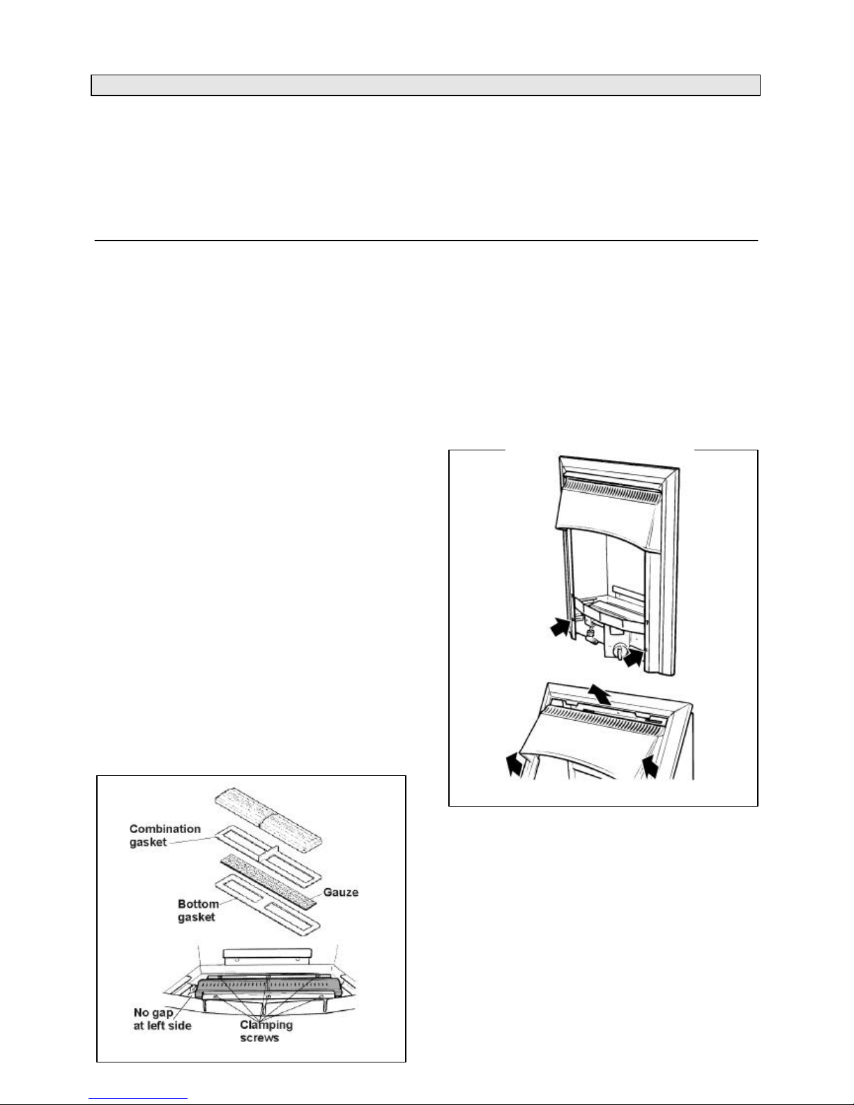
12.1 TO REPLACE BURNER PLAQUES
(See figure 25)
12.1.1 Remove the 5 loose coals, ceramic side walls,
front base coal, rear base coal and ceramic back wall.
The plaques can be then be removed as follows without
detaching the front surround or front casting.
12.1.2 Remove the plaque clamping strips by
detaching 6 screws.
12.1.3 Remove the plaques and the combination
gasket between and under the plaques. If necessary remove
the gauze and the gasket beneath it.
12.1.4 If necessary fit a new gasket below the gauze.
Clean and replace the gauze. Fit a new combination gasket
below the plaques. Push the gasket ends inwards to form a
dividing gasket between the plaques.
12.1.5 Place the new left hand plaque in position.
The left side of the plaque must touch the inside edge of
the retaining flange at the left side of the burner well.
12.1.6 Place the new right hand plaque in position.
Make sure that the centre section of the combination
plaque is between the two plaques. If there is any play
between the plaques and the end retaining flanges, push
the plaques firmly to the left squeezing the centre section of
the combination gasket between the two plaques. Any gap
should be between the right side of the plaque and the right
side retaining flange.
12.1.7 Fit the front and rear plaque clamping strips.
Make sure that the plaques are as far to the left as possible.
. It is important that the left side plaque is accurately positioned
so that it has the correct relationship to the pilot. Fully tighten
the clamping strips.
12.1.8 Refit the ceramic fuel effects and walls as
described in section 9 of this manual.
12.2 TO REMOVE THE FRONT SURROUND
12.2.1 Remove the bottom front cover casting.
12.2.2 Lift the casting clear. (Where applicable by
lifting the fire front casting up and forward to release the
locating screw heads at the back of the casting from the
keyholes in the surround sides.)
12.2.3 Remove the two screws securing the bottom
of the front surround to the sides of the convection box.
Raise the front surround to allow the retaining lugs at the
top to clear the slots in the convection box hood and then
lift clear (see figure 26).
12.2.4 Replace in the reverse order.
Fig. 25 Burner plaques
Fig. 26 Front surround removal
Page 17
17
12.3 TO REMOVE THE COMPLETE
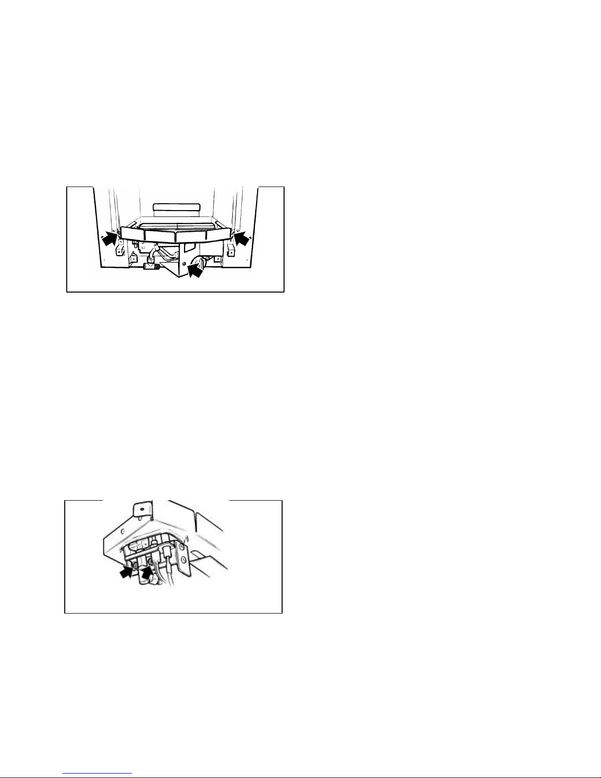
BURNER UNIT (See figure 27)
12.3.1 Remove the 5 loose coals, ceramic side walls,
front base coal, rear base coal and ceramic back wall.
12.3.2 Remove the front surround unit - See section
12.2.
12.3.3 Support the inlet isolating elbow to avoid
straining the pipework and disconnect the appliance from
the elbow.
12.3.4 Detach the burner unit from the convection box
by removing 3 screws.
12.3.5 Replace in the reverse order.
12.4 TO REMOVE THE PILOT UNIT (See
figure 28)
12.4.1 Remove the burner unit - See section 12.3.
12.4.2 Disconnect the electrode lead from tab
underneath the electrode.
12.4.3 Undo the thermocouple nut at the gas tap.
12.4.4 Disconnect the pilot pipe from the pilot unit
elbow.
12.4.5 Remove the first screw securing the dust cage to
the pilot unit / burner. Carefully remove the dust cage and
place aside.
12.4.6 Remove the second screw securing the pilot unit
to the burner. Remove the pilot unit and place it aside
12.4.7 Refit in the reverse order
Note 1 The pilot unit must be replaced as a whole assembly.
Its individual components are not separately replaceable.
2. Once removed, ensure that the dust cage is cleaned
before refitting. Make sure that it locates squarely onto the pilot
unit without any gaps between the cage edges and the pilot unit.
12.5 TO REMOVE THE GAS TAP/F.S.D.
12.5.1 Remove the burner unit - See section 12.3.
12.5.2 Disconnect the electrode lead from tab
underneath the electrode.
12.5.3 Undo the thermocouple nut at the gas tap.
12.5.4 Disconnect the inlet pipe at the tap end.
12.5.5 Disconnect the pilot pipe at the tap end.
12.5.6 Disconnect the main burner pipe at the tap end.
12.5.7 Pull off the control knob.
12.5.8 Remove the gas tap fixing nut. Pull the tap clear
of the control plate.
12.5.9 Replace in the reverse order.
Fig. 27 Burner attachment points
Fig. 28 Pilot unit attachment points (Dust cage not shown
for clarity)
Page 18
18
12.6 TO REMOVE THE PIEZO
GENERATOR
12.6.1 Remove the gas tap as section 12.5.
12.6.2 Make sure that the tap is in the off position.
12.6.3 Remove the circlip holding the piezo unit to the
tap. Remove the piezo unit.
12.6.4 Replace in the reverse order.
12.7 TO GREASE THE CONTROL
TAP/F.S.D.
12.7.1 Detach the tap and remove the piezo generator
as section 12.6 making sure that the tap is in the off
position.
12.7.2 Remove the two screws from the head of the tap.
Remove the niting head and spindle complete with collar
and spring.
12.7.3 Note the position of the slot in the plug - mark
its position on the tap body.
12.7.4 Remove the plug rotating slightly while pulling.
12.7.5 Clean and grease the plug lightly with a suitable
grease. Do not apply excessive grease. Particularly, make
sure that the gas ports in the tap are not restricted by
grease.
12.7.6 Push the plug into the tap body and position the
slot in line with the mark previously made on the tap body.
12.7.7 Reassemble the niting head and spindle
complete with collar and spring making sure that the
components are correctly engaged. Check the operation of
the tap.
12.7.8 Refit the piezo generator.
12.8 TO REMOVE THE MAIN BURNER
INJECTOR
12.8.1 Remove the burner unit - See section 12.3.
12.8.2 Disconnect the main burner pipe from the
injector at the venturi end. If necessary, loosen the pipe at
the gas tap end to swing the pipe clear of the injector.
12.8.3 Unscrew the injector from the rear support
bracket.
12.8.4 Refit in the reverse order.
12.9 TO REMOVE THE APPLIANCE
FROM THE FIREPLACE
12.9.1 Remove the 5 loose coals, ceramic side walls, front
base coal, rear base coal and ceramic back wall.
12.9.2 Remove the front surround unit - See section
12.2.
12.9.3 If the appliance is fixed to the fireplace floor
remove the burner unit (See section 12.3) and
remove the two floor fixing screws.
12.9.4 If the appliance is attached by the front fixing
method (See section 7.1), remove the four screws
attaching the convection box side flanges.
12.9.5 If the appliance is fixed by the cable retention
method (See section 7.2), slacken the hexagonal
adjusters on the cable retainers and unscrew the
thumbscrews to release the cables.
12.9.6 Refit as described in the relevant installation
sections. Make sure gas soundness, sealing,
spillage test and performance are satisfactory.
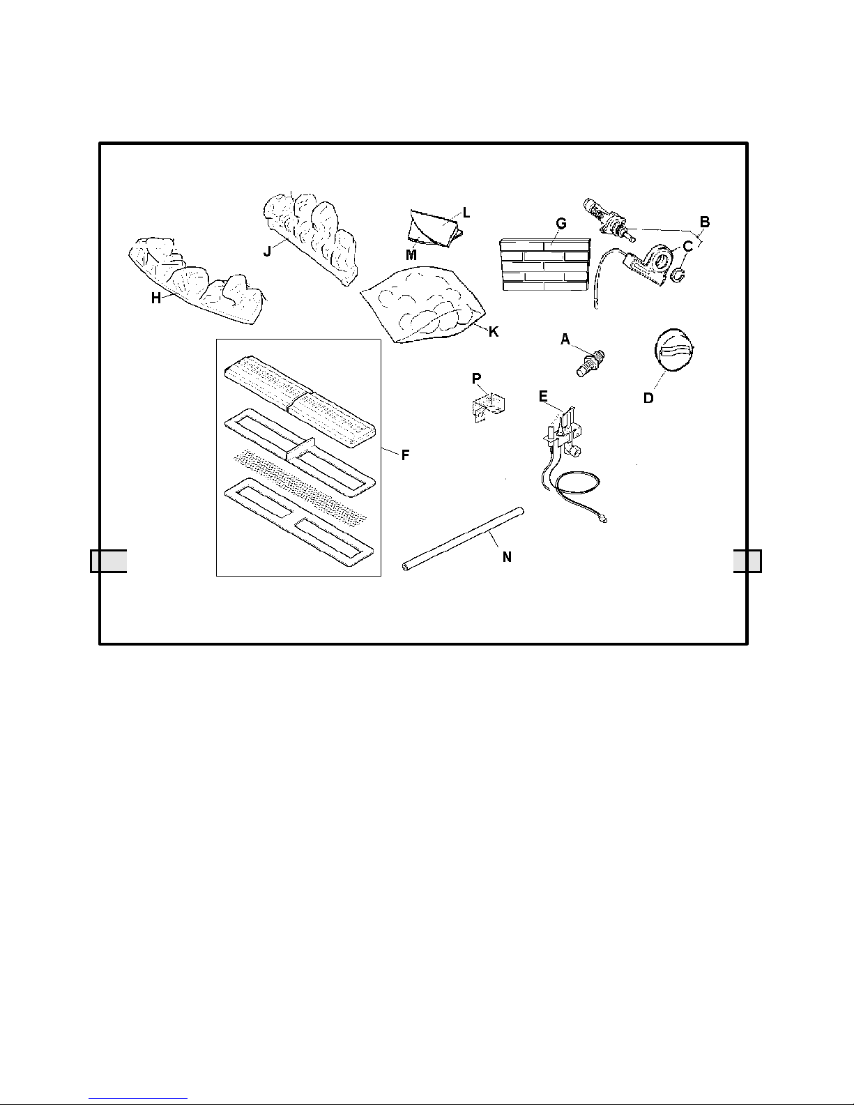
13. SHORT LIST OF SPARES
Page 19

19
KEY DESCRIPTION NO. OFF PART NO.
A Injector Bray cat 18 size 360 For Natural Gas Appliances 1 541609
Injector Bray cat 18 size 170 For Propane Appliances 571709
B Gas tap & spark generator 1 569429
C Spark generator 1 521069
D Control knob 1 545979
E Pilot unit For Natural Gas Appliances 1 540979
Pilot unit For Propane Appliances 544929
F Burner plaque & gasket set 1 569439
G Ceramic rear wall 1 545999
H Front coal halves 1 569449
J Rear base coal 1 569459
K Pack of loose coals 1 569469
L Ceramic side wall - right side 1 546039
M Ceramic side wall - left side 1 546049
N Smoke match tube 1 541169
P Dust cage 1 567619
- Installation template (Not illustrated) 1 546059
Page 20
20
Safety First.
Valor fires are CE Approved and designed to meet the appropriate British
Standards and Safety Marks.
Quality and Excellence.
At the heart of every Valor fire.
All Valor fires are manufactured to the highest standards of quality and
excellence and are manufactured under a BS EN ISO 9001 quality system
accepted by the British Standards Institute.
The Highest Standards
Valor is a member of the Society of British Gas Industries which works to
ensure high standards of safety, quality and performance.
Careful Installation
Valor is a Corgi registered company. All our gas fires must be
installed by a competent Corgi Registered Installer in accordance
with our Installer Guide and should not be fitted directly on to a
carpet or floor of combustible material.
Valor Heating, Erdington, Birmingham B24 9QP
Because our policy is one of constant development and improvement, details may vary slightly from
those given in this publication
© Valor Heating
 Loading...