

Valor BOLERO BR626 Installer's Manual
For
G.C. No. 32-032-10
600B350/04
INSTALLER GUIDE
VALOR BOLERO
(MODEL BR626)
9500436- Brass
9500437 – Chrome
9500438 - Black
Inset Live Fuel Effect Gas Fire
GB IE
Please keep in a saf e pla ce f or future reference

2
This Installer Guide gives sufficient details to enable the
appliance to be installed and maintained. If further
information is required, our Valor AdviceLine will be
pleased to help.
Please telephone 0345 626341 (Local call rates apply)
Please leave this Installer Guide with the us er
This appliance is for use with natural gas (G20)
This appliance is for use in the United Kingdom (GB)
and the Republic of Ireland (IE) only.
Conversion to LPG (Propane) can be undertaken by
use of a Valor conversion kit 591159.
CUSTOMER CARE

3
INSTALLATION NOT ES
In your own interest and for safety, in th e United Kingdom, it is the la w that all gas appliances are installed by
competent persons in accordance with the current edition of the Gas Safety (Installation & Use) Regulations and
Amendments. Failure to install the appliance correctly could lead to prosecution. The Confederation for the
Registration of Gas Installers (CORGI) req uire s i ts me mbe rs to wo rk to re c ogni se d standards.
This product uses fuel effe ct pieces, burner compartmen t walls and gas kets contain ing Refractor y Ceramic Fibr es
(RCF), which are ma n-made vitreous silicat e fibres. Excessive exposur e to these materials may cause temporary
irritation to eyes, skin an d respir atory tr act. C onsequ ently, it mak es sense t o take car e wh en h andlin g thes e ar ticl es
to ensure that the release of dust is kept to a m inim u m . To ensure that the r elease of fibres from t h es e RC F articles
is kept to a minimum, during installation and servicing we recommend that you use a HEPA filtered vacuum to
remove any dust and soot accumulated in and around the fire before and after working on the fire. When replacing
these articles we recommend that the replaced items are not broken up, but are sealed within a heavy duty
polythene bag, clearly labelled as RCF waste. This is not classified as “hazardous waste” and may be disposed of at a
tipping site licens ed for the disposal of indus trial waste. Prot ective clothing is not re quired when handling th ese
articles, but we recommend you fo llow the normal hyg iene rules of not sm oking, eating or drinking in the wor k
area and always wash your hands before e ati ng or dri n ki ng .
This appliance does not contain any component manufactured from asbestos or asbestos related products.
The appliance data la bel is on the control plate below the right sid e of t he burner tray. It is vis ible when the bottom
front cover is removed.
The installation must be in accordance with these instructions.
In the United Kingdom the installation must also be in accordance with:
a) All the relevant parts of local regulations.
b) The Building Regulati ons iss ued by the D epartm ent of th e Environ ment or the Build ing St andar ds (Scot land)
(Consolidation) Regulations issued by the Scottish Developme nt De p artment.
c) All relevant codes of practice.
d) The relevant parts of the current editions of the following British Standards:-
BS 715
BS 1251
BS 1289 Part 1
BS 1289 Part 2
BS 4543 Part 2
BS 5440 Part 1
BS 5440 Part 2
BS 5871 Part 2
BS 5872 Part 3
BS 6461 Part 1
BS 6891
In the Republic of Ireland the installation must also conform to the relevant parts of:
a) The current editions of:-
IS 813 (1996 as amended)
ICP3
IS327
b) All relevant national and local rules in force.
If the appliance is int ended t o be insta lled to a chimn ey which wa s pr eviously used for solid fuel, the flu e must be
swept clean prior to installation. All flues shoul d b e i nspecte d for soundne ss and fre e d om from bl ockage s.
The minimum effective height of the chimney or flue must be 3m (10ft) from the hearth to the point of
termination of the flue.
The chimney or flue must have any damper or restrictor removed, or pe rmane ntly secure d i n the fully open
position.
The flue must not be used for any other appliance or application.
If the fireplace opening is of unde rfloo r draug ht type, it must be sealed to stop any draughts.

4
A fireguard complying with BS6539 or BS6778 should be fitted for the protection of young children, the elderly, or
the infirm.
In the United Kingdom (GB) no spec ial ventilation bricks or vents are required in the ro om for this appliance.
However, any requirement relating to other appliances which may be in the same room must be taken into
consideration.
In the Republic of Ireland (IE), permanent ventilation must comply with the regul ations curre ntly i n force.
An extractor fan may only be used in the same room as this appliance, or in any area from which ventilation for the
appliance is taken , if it does not affec t the safe performanc e of the appliance. Note the spillag e test requirement s
detailed further on in this manual. If the fan is lik ely to affect the applian ce, the appliance mu st not be installed
unless the fan is permanently disconnected.
The appliance is fitted with an A.S.D (A tmosphere sensing d evice). If the applia nce closes down af ter a period of
operation for no apparent reason, the consumer should be informed to stop using the appliance until the
installation and appliance have been thoroughly checked. The A.S.D will shut the appliance down if an
unacceptable amount of harmful products of combustion accumulate. Under no circumstances should the A.S.D
be altered or bypassed in any way. Only a genuine Valor s upplied replacement part should be fitted. The individual
A.S.D components are not replaceable.
Note that soft wall cover ings (e.g. embossed vin yl, etc.) are easily affe cted by heat. They may scorch or become
discoloured when close to a heating appliance. Please bear this i n mind when i nstalling .
TECHNICAL SPECIFICATION
Fire surround height: 620mm
Fire surround width 560mm
Appliance insert depth: 233mm
Height of opening required: 535mm min.
570mm max.
Width of opening required: 405mm min.
490mm max.
Gas: Natural Gas (G20) LPG Propane (G31)
Conversion kit 591159.
Inlet Pressure: 20mbar (8in. w.g) 37mbar (14.8in. w.g)
Max. input (Gross): 6.85kW (23,375 Btu/h) 6.7kW (22,860 Btu/h)
Min. input (Gross): 2.2kW (7,500Btu/h) 3.6kW (12,280Btu/h)
Burner Test Pressure (cold): 17.3+0.75mbar (6.9+
0.3in. w.g.) 35.1+0.75mbar
(14.1+0.3in. w.g.)
Gas connection: 8mm pipe.
Burner Injector: Bray Cat 31 Size 440 Bray Cat 18 Size 180
ASD Pilot:: SIT ref. OP NG 9030 SIT ref. OP LPG 9222
Ignition: Piezo electric. Integral with gas tap
Aeration: Non adjustable.
Clearance to combustible side panels: 100mm
The minimum height from the top surface of the hearth to the underside of any shelf made from wood or other
combustible materials is as follows:-
• For a shelf up to 150mm deep
Minimum height = 750mm.
• For a shelf deeper than 150mm
Minimum height = 750mm + 12.5mm for every 25mm depth over 150mm.
PACK CONTENTS
1 Burner & Fire Box Unit 2 Cable Retention Bolts
1 Nut & Olive for 8mm inlet pipe 2 Fire Retaining Cables
1 Front Coal 1 Owners Guide
1 Main Coal Bed 1 Burner Tray Trim
1 Pack 14 Loose Coals 1 Rear Support Bracket
3 Self Adhesive Foam Seals 1 Floor Sealing Tape
2 Fibre Wall Plugs 1 Front Casting Pack
2 Eyebolts 1 Guarantee Pack
5
LOCATION
This appliance is not suitable for installation in a room or internal space containing a bath or shower, or where
steam is regularly present or in a private garage.
This appliance is suitable for the following:-
1. A masonry chimney with a minimum diameter of 175mm (7”) free from any obstruction, and with any
damper or restrictor plate in the chimney removed or secured, and having a minimum effective flue height of
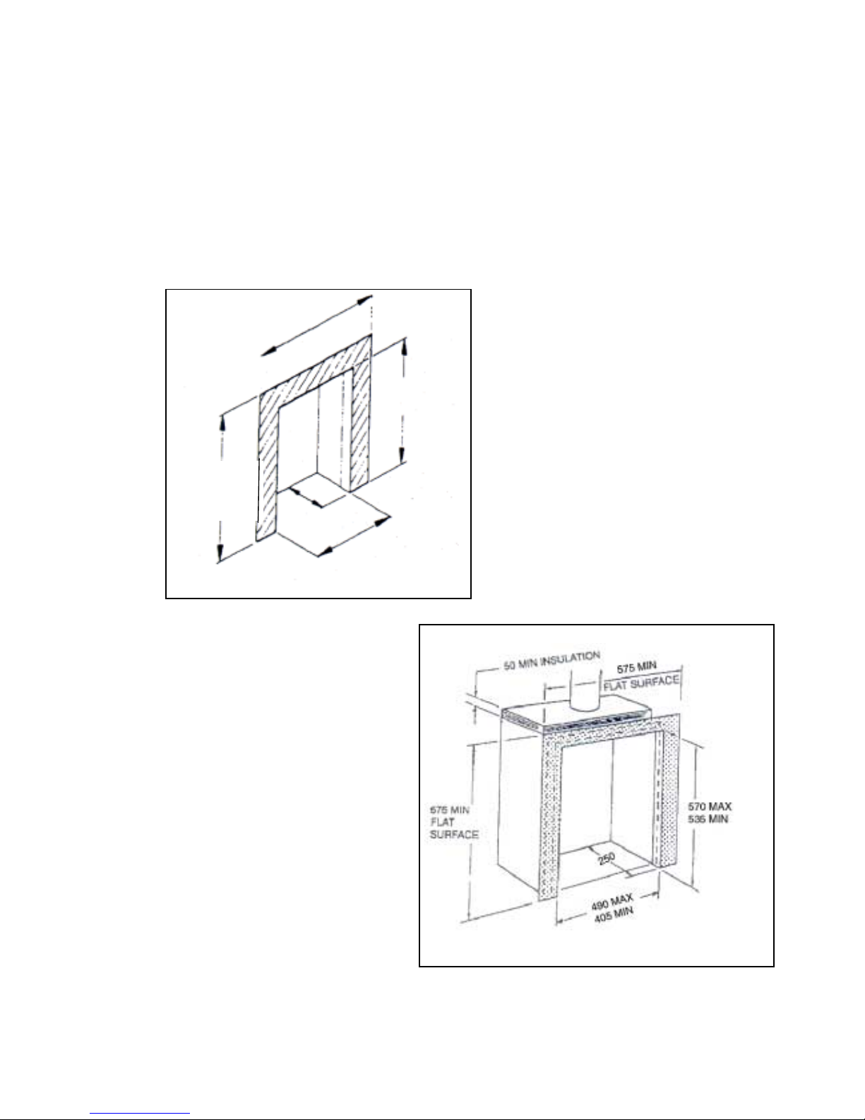
3m (10ft). Note the releva nt flat s urfac e area r equirem ent (F igure 1). A ma sonry chimney having a cor rectly
installed flue liner to BS715 and with a minimum flue diameter of 125mm is also acceptable. Chair brick
removal may be required. At least 50mm clearance must be available from the flue outlet to any fireplace
component. The applian ce is designed to cater for low l intel installations (min h eight 505mm) providing a
minimum distance of 45mm is maintained between the lintel and the front face of the fireplace (i.e. fire
surround with a min rebate of 45mm).
2. A sheet metal flue system conforming with
BS4543 or BS715, the flue diameter being a
minimum of 125mm (5”) (see Figure 3) with
a minimum internal depth of 240mm.
Incombustible mineral wool insulation of not
less than 50mm thickness mus t be applied t o
the top surface of the system firebox, as
shown in figure 3.
Fi
g
ure 1 Masonry Fireplace
575 MIN
FLAT
SURFACE
575 MIN FLAT
SURFACE
570 MAX
535 MIN
490 MAX
405 MIN
250
Figure 2 Factory Made Flue System
6
Figure 4.
Fire Surround: This appliance may be installed
with a surround with a minimum approved
temperature rating of 150 degrees. The fire
surround must be sealed to the wall.
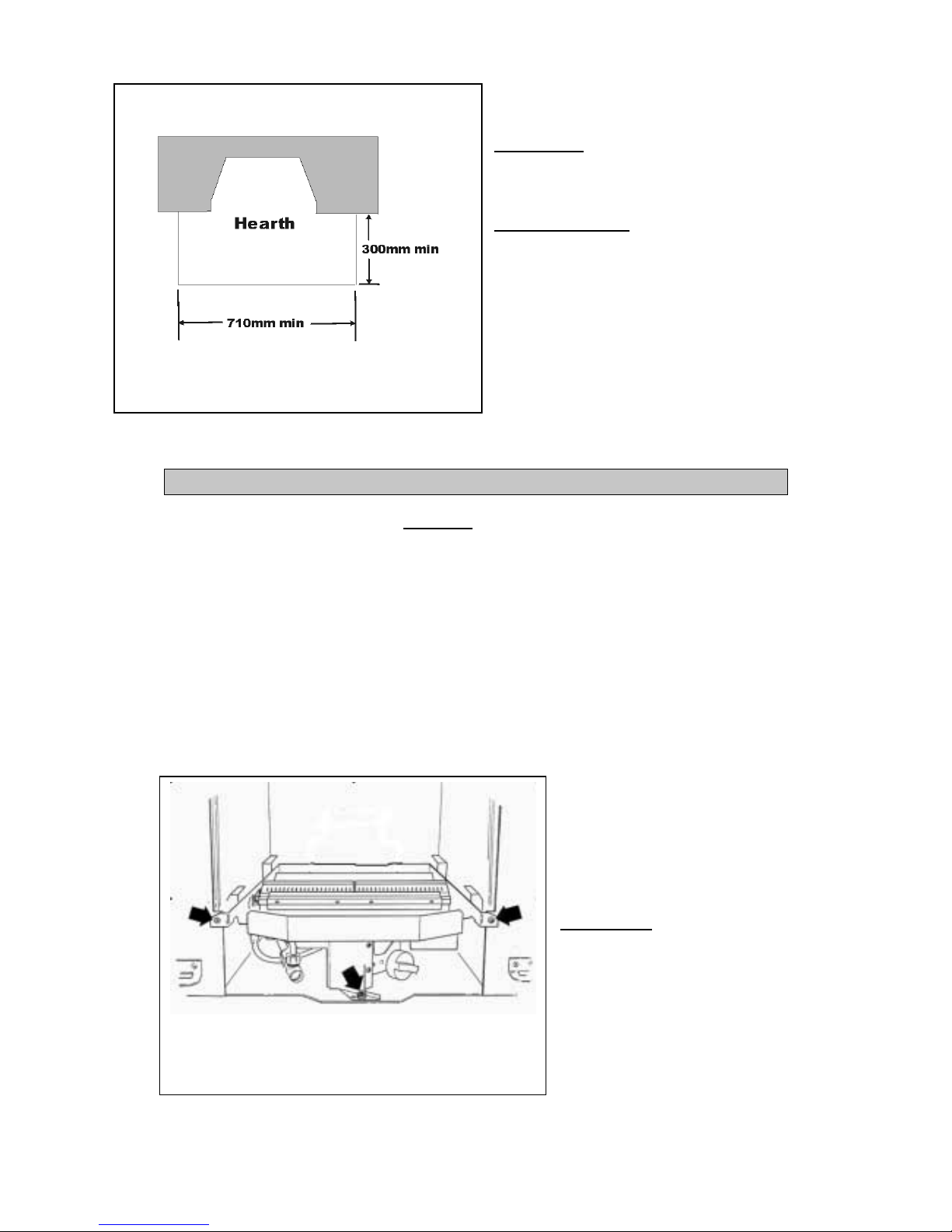
Hearth Requirements: The appliance must be
mounted on a non-combustible hearth in
accordance with Figure 3. The hearth material must
have a minimum thickness of 12.5mm (1/2”). The
periphery of the hearth (or fender) should be at least
50mm above floor level to discourage the placing of
carpets or rugs over it .
INSTALLATION AND COMMISSIONING INSTRUCTIONS
PLEASE READ CAREFULLY BEFORE STARTING WORK
Fireplace, Flue and Ventilation Details
Read the important installation notes on the previous pages bef ore proceeding with the in stallation of your fire.
Only when you have complied with all the requirements should you proceed any further. Note the hearth
requirements.
Remove any transit tape and packing and inspect for any evidence of mishandling which might affect the
performance. Each unit is f lame and soundness tested before it leaves the factory an d as a result there may be
slight discoloration around the burner ports.
8mm (5/16) Bundy or semi-rigid tubing must be used to connect the appliance to the gas supply.
If a concealed gas pipe fixing is to be used, offer the gas pipe through the appropriate grommet. A nut and olive
are provided for an 8mm pipe inlet connection t o t h e elbow at th e bottom fron t of th e appliance. The elbow
can be rotated to allow a connection from any direction. The elbow inclu d es a va lve f or isolating the gas supply.
The burner assembly is retained by t w o
screws positioned at each side of the
burner tray assembly and one positioned
through the front leg. (see F ig.4).
Carefully remove the burn er assembly
by lifting and sliding forward from the
firebox.
Fit Foam Seals: A foam seal is
supplied which will need to be attach ed
to the rear face of the firebox frame on
all three sides. Ensu r e th a t all j o in t s a r e
butted together to prevent air gaps.
Figure 3 Hearth
 Loading...