

Valor Black Beauty Radiant, Black Beauty Radiant 340 Installer's Manual
600B718/08
INSTALLER GUIDE
THIS APPLIANCE IS FOR USE WITH NATURAL GAS (G20)
THIS APPLIANCE IS FOR USE IN THE UNITED KINGDOM (GB) AND
THE REPUBLIC OF IRELAND (IE) ONLY.
We trust that this Installer Guide gives sufficient details to enable the appliance to be
installed and maintained satisfactorily. However, if further information is required, our
Valor Technical Helpline will be pleased to help.
Please telephone 08706 061 065 (National call rates apply in the United Kingdom).
INSTALLER: Please leave this guide with the owner
© Valor Heating
BLACK BEAUTY
Radiant
Gas Fire
MODEL 340
(GC No. 32-032-33)

INSTALLER’S GUIDE
Page 2
CONTENTS
1 SAFETY ......................................................................................................................3
2 LIST OF ACCESSORIES.........................................................................................3
3 APPLIANCE DATA ..................................................................................................4
4 GENERAL INSTALLATION REQUIREMENTS ................................................5
5 PRE-INSTALLATION PREPARATION ............................................................ 11
5.1 Unpacking ............................................................................................................. 11
5.2 Fireplace Flue Pull ................................................................................................ 11
5.3 Appliance Preparation ........................................................................................... 11
5.4 Fit The Closure Plate............................................................................................. 12
6 APPLIANCE INSTALLATION............................................................................ 14
6.1 Installing To A Hearth .......................................................................................... 14
6.2 Wall Mounting ....................................................................................................... 14
6.3 Gas Supply Connection......................................................................................... 14
6.4 Radiants Installation.............................................................................................. 14
6.5 Flue Restrictor Adjustment ................................................................................... 15
7 CONTROL & PRESSURE CHECKS .................................................................. 15
7.1 Check Control Settings ......................................................................................... 15
7.2 Flame Supervision & Spillage Monitoring System .............................................. 16
7.3 Check Reference Pressure..................................................................................... 16
8 OUTER CASE FITTING ....................................................................................... 17
9 SPILLAGE CHECK ............................................................................................... 17
10 FINAL REVIEW..................................................................................................... 18
11 SERVICING & PARTS REPLACEMENT ......................................................... 19
11.1 To Replace Radiant(s)........................................................................................... 19
11.2 To Remove the Outer Case ................................................................................... 19
11.3 To Replace the Pilot Unit...................................................................................... 19
11.4 To Remove the Piezo Generator ........................................................................... 20
11.5 To Remove The Complete Burner Module, Pipes and Pilot ................................ 20
11.6 To Grease the Gas Tap .......................................................................................... 21
REPLACEMENT PARTS – SHORT LIST ................................................................. 21
Valor Heating, Erdington, Birmingham B24 9QP
www.valor.co.uk
Because our policy is one of constant development and improvement, details may vary slightly
from those given in this publication.

INSTALLER’S GUIDE
Page 3
1 SAFETY
Installer
• Before continuing any further with the installation of this appliance please read the
following guide to manual handling
• The lifting weight of this appliance is 15.74 kg. One person should be sufficient to lift
the fire. If for any reason this weight is considered too heavy then obtain assistance.
• When lifting always keep your back straight. Bend your legs and not your back.
• Avoid twisting at the waist. It is better to reposition your feet.
• Avoid upper body/top heavy bending. Do not lean forward or sideways whilst
handling the fire.
• Always grip with the palm of the hand. Do not use the tips of fingers for support.
• Always keep the fire as close to the body as possible. This will minimise the
cantilever action.
• Use gloves to provide additional grip.
• Always use assistance if required.
2 LIST OF ACCESSORIES
Description Part number
Spigot extension 0595191
INSTALLER’S GUIDE
Page 4
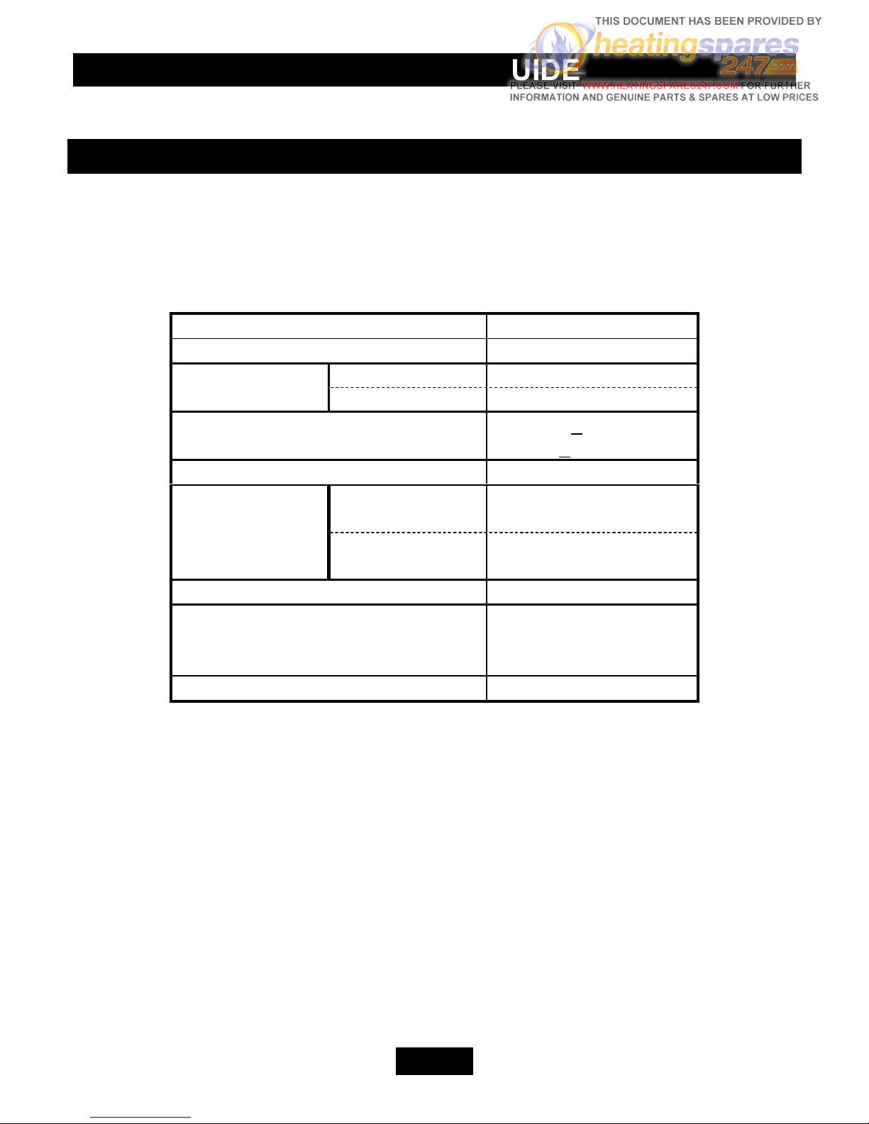
3 APPLIANCE DATA
This appliance does not contain any component manufactured from asbestos or asbestos
related products.
The appliance data label is on the inner face of the back panel at the lower left-hand side.
It is visible when the outer case is removed.
Gas Natural (G20)
Inlet Pressure 20mbar
Gross Heat Input Max. 5.6kW (19,100Btu/h)
Min. 1.25kW (4,300Btu/h)
Burner Test Pressure (Cold) 17.95+0.75mbar
(7.2+0.3in w.g.)
Gas Connection 8mm pipe
Burner Injector Upper
(Centre Radiant)
Bray Cat. 16 Size 120
Lower
(Outer Radiants)
Bray Cat. 28 Size 250B
Pilot & Atmosphere Sensing Device OPNG9093
Ignition Twin-spark Piezo-
electric integral with
gas tap
Aeration Non-adjustable

INSTALLER’S GUIDE
Page 5
4 GENERAL INSTALLATION
REQUIREMENTS
4.1 The installation must be in accordance with these instructions.
For the user’s protection, in the United Kingdom it is the law that all gas appliances are
installed by competent persons in accordance with the current edition of the Gas Safety
(Installation and Use) Regulations. Failure to install the appliance correctly could lead to
prosecution. The Council for the Registration of Gas Installers (CORGI) requires its
members to work to recognised standards.
In the United Kingdom the installation must also be in accordance with:
• All the relevant parts of local regulations.
• All relevant codes of practice.
• The relevant parts of the current editions of the following British Standards:-
BS 715
BS 1251
BS 1289 Part 1
BS EN 1806
BS 4543 Part 2
BS 5440 Part 1
BS 5440 Part 2
BS 5871 Part 1
BS 6461 Part 1
BS 6891
• In England and Wales, the current edition of the Building Regulations issued by the
Department of the Environment and the Welsh Office.
• In Scotland, the current edition of the Building Standards (Scotland) Regulations
issued by the Scottish Executive.
• In Northern Ireland, the current edition of the Building regulations (Northern Ireland)
issued by the Department of the Environment for Northern Ireland.
• In the republic of Ireland the installation must also conform to the relevant parts of:
• The current edition of IS 813
• All relevant national and local rules in force.
4.2 If the appliance is intended to be installed to a chimney that was previously used
for solid fuel, the flue must be swept clean prior to installation. All flues should be
inspected for soundness and freedom from blockages.
4.3 Any chimney dampers or restrictors should be removed. If removal is not possible
they must be fixed in the open position.
4.4 In the United Kingdom (GB) special ventilation bricks or vents are not normally
required in the room for this appliance.
In the Republic of Ireland (IE), permanent ventilation must comply with the regulations
currently in force.
INSTALLER’S GUIDE
Page 6
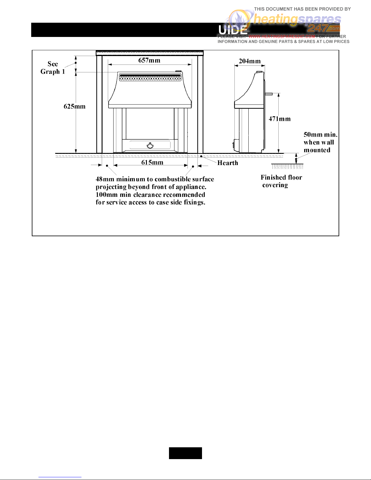
Figure 1. Dimensions & clearances
4.5 Note that soft wall coverings (e.g. embossed vinyl, etc.) are easily affected by heat.
They may scorch or become discoloured when close to a heating appliance. Please bear
this in mind when installing.
4.6 The minimum side clearances to combustible surfaces and recommended side
access clearances are given in figure 1.
4.7 The appliance must not be installed in any room, which contains a bath, or shower
or where steam is regularly present.
INSTALLER’S GUIDE
Page 7
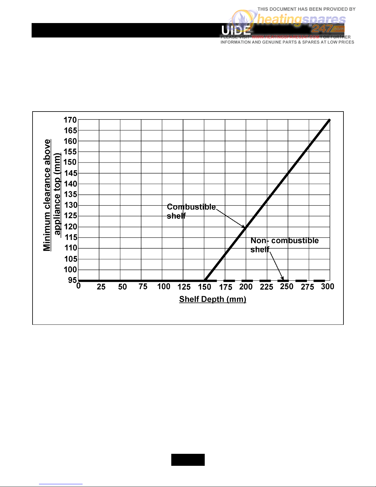
Graph 1 Shelf clearances
4.8 Allow a minimum clearance of 95mm from the top surface of the appliance case to
the underside of any shelf whether it is made from combustible or non-combustible
materials. This clearance is necessary to allow the case to be lifted off for servicing and
also allows the owner sufficient access to operate the control knob.
For a shelf made from wood or other combustible materials deeper than 150mm, the
minimum clearance must be as shown in graph 1.
4.9 In the United Kingdom, as supplied, this appliance can be installed in the following
situations: Note: A spigot extension is available (Valor part number 0595191). When fitted this shall
extend through the closure plate for at least 15mm and have a minimum clearance of
50mm from the end to any surface.
4.9.1 Conventional Fireplace
The fireplace opening must be within the following dimensions:
Width Max. 440mm
Min. 305mm
Height Max. 610mm
★
Min. 525mm
 Loading...