

Valor ALTON DIMENSION, BAUHAUS DIMENSION, DOWNTON DIMENSION, CLIFTON DIMENSION, BLENHEIM DIMENSION User Manual
Page 1
The product complies with the European Safety Standards EN60335-2-30 and the European Standard Electromagnetic Compatibility (EMC)
EN55014, EN60555-2 and EN60555-3. These cover the essential requirements of EEC Directives 2006/95/EC and 2006/108/EC
8/53139/0 (UK) Issue 2
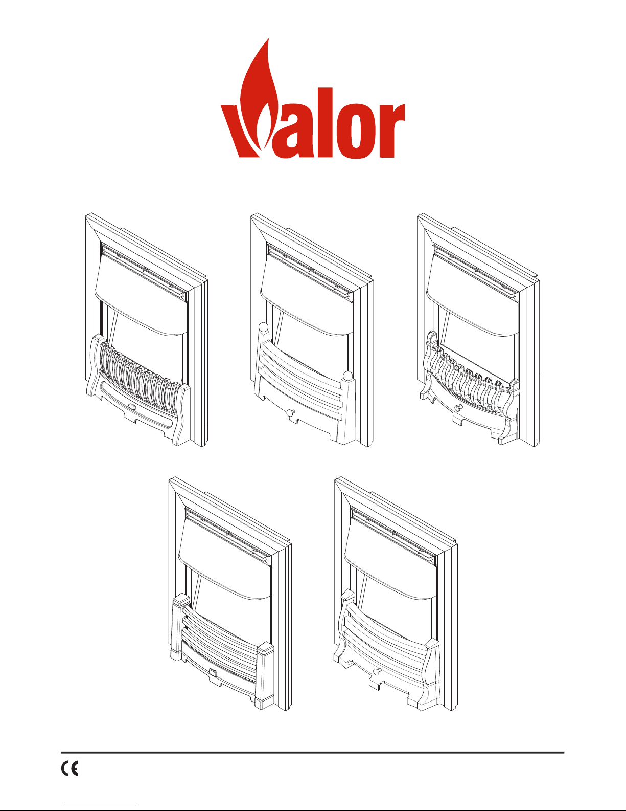
DIMENSION ELECTRIC RANGE
ALTON DIMENSION
CLIFTON DIMENSION DOWNTON DIMENSION
BAUHAUS DIMENSION BLENHEIM DIMENSION
Page 2

Dimension Inset Electric Fire
Introduction
Thank you for choosing this Valor electric re. Please read this information guide carefully in order to safely install, use
and maintain your product.
Important Safety Advice
When using electrical appliances, basic precautions should always be followed to reduce the risk of
re, electrical shock and injury to persons, including the following:
1. OVERHEATING
WARNING: In order to avoid overheating, do not cover the heater. Do not place material or garments
on the heater, or obstruct the air circulation around the heater. The heater carries a DO NOT
COVER warning.
2. DAMAGE.
If the appliance is damaged, check with the supplier before installation and operation. If the supply
cord is damaged it must be replaced by the manufacturer or service agent or a similarly qualied
person in order to avoid a hazard.
3. LOCATION
Do not use outdoors.
Do not use in the immediate surroundings of a bath, shower or swimming pool.
Do not locate the heater immediately below a xed socket outlet or connection box.
Ensure that furniture, curtains or other combustible material are positioned no closer than 1 metre
from the heater.
4. PLUG POSITIONING
The appliance must be positioned so that the plug is accessible.
Keep the supply cord away from the front of the heater.
5. USE OF OTHER CONTROLS
Do not use this heater in series with a thermal control, a program controller, a timer or any other
device that switches on the heat automatically, since a re risk exists when the heater is accidentally
covered or displaced.
6. UNPLUGGING
In the event of a fault unplug the device. Unplug the device when not required for long periods.
7. OWNER/USER
WARNING: This heater is not equipped with a device to control the room temperature. Do not use
this heater in small rooms when they are occupied by persons not capable of leaving the room on
their own, unless constant supervision is provided.
This appliance can be used by children aged from 8 years and above and persons with reduced
physical, sensory or mental capabilities or lack of experience and knowledge if they have been given
supervision or instruction concerning use of the appliance in a safe way and understand the hazards
involved. Children shall not play with the appliance. Cleaning and user maintenance shall not be
made by Children without supervision. Children of less than 3 years should be kept away unless
continuously supervised. Children aged from 3 years and less than 8 years shall only switch on/off
the appliance provided that it has been placed or installed in its intended normal operating position
and they have been given supervision or instruction concerning use of the appliance in a safe way
and understanding the hazards involved. Children aged from 3 years and less than 8 years shall not
plug in, regulate and clean the appliance or perform user maintenance.
CAUTION - Some parts of this product can become very hot and cause burns. Particular
attention has to be given where children and vulnerable people are present.
8. ELECTRICITY
WARNING – THIS APPLIANCE MUST BE EARTHED.
This heater must be used on an AC ~ supply only and the voltage marked on the heater must
correspond to the supply voltage. Before switching on, please read the safety advice and operating
instructions.
Page 3

General Information
The re incorporates a ame effect, which can be used with or without heating, so that the comforting effect may be
enjoyed at any time of the year. Using the ame effect on its own requires little electricity. A choice of 650W or 1.3kW
heat output is provided by the fan heater which is located at the top of the unit.
Please note: If used in an environment where background noise is very low, it may be possible to hear a sound which is
related to the operation of the ame effect. This is normal and should not be a cause for concern.
Before switching on the appliance, please read the safety warnings and operating instructions.
Installation Instructions
This section describes how to set up your re.
Before installing this appliance in an existing chimney, we recommend that;
1. You have your chimney cleaned by a competent chimney sweep.
2. You block off the chimney ue.
This procedure is important for the efcient operation of the heating unit and will also reduce heat loss up the chimney.
BEFORE YOU START
1. Ensure that all packing items are removed (read any warning labels carefully) and retain all packing for possible future
use e.g. in the event of moving house or returning the appliance to your supplier.
2. Ensure the appliance is disconnected from the power supply before installation.
3. Before connecting the appliance, check that the supply voltage is the same as that stated on the heater.
INSTALLATION
The appliance must be secured into position to prevent it from being tipped over. There are a number of methods to x
the appliance in place.
- Method A - Screwing the appliance to the replace surround
- Method B - Securing the appliance to the back of the replace with the steel cable and clamp
- Method C - Securing the appliance with optional spacer frame
Note - If xing to a marble replace surround, it is recommend that Method B is used.
The appliance can be tted into replaces or surrounds where the following dimension are available (Fig. 1).
Width: 410mm - 450mm Height: 560mm - 590mm Depth: 65mm (Minimum)
Method A (Fig. 2)
Place the appliance into the replace opening and ensure the appliance is positioned in the middle of the opening.
Locate the four xing holes in the side anges (Fig. 2). Mark the holes so that their position is clear when the appliance
is removed. With the appliance removed, drill an appropriate size hole in each of the marked positions for the wall plug
supplied. Insert the four wall plugs and reposition the appliance, aligning the holes with the wall plugs. Using the four
wood screws supplied, secure the appliance in position.
Method B (Fig. 3 & Fig. 4)
Note: This method of securing is recommended when it is not suitable to screw the appliance to the replace surround.
The xing kit supplied with the appliance includes a steel cable, eyescrew and cable clamp. These items can be used
to secure the appliance in place. Begin by marking a hole in the centre of the back of the replace approximately 565575mm from the bottom of the replace (Fig. 3). Drill an appropriate size hole in the marked position, insert a wall plug
and screw the eyescrew into the wall plug. Re-position the appliance in front of the opening but do not insert it into the
opening. Locate the two same sized small holes at the top of the side anges of the re chassis. Thread about 300mm
of the steel cable into the bottom small hole on the left hand side ange of the appliance (Fig. 4 - Step 1). Thread the
other end of the cable through the remaining small hole directly above the other small hole. Continue to push the cable
through this hole until the cable locks into place (Fig 4a). (In order to get the cable to snap into place, both ends of the
cable may need to be pulled from the rear of the appliance.)
Next, thread the longer piece of cable through the eyescrew at the back of the replace opening (Fig. 4 - Step 2). From
the back of the appliance, thread the longer piece of wire through the top small hole on the right hand side ange of the
re chassis (Fig. 4 - Step 3).
Locate the appliance in the replace opening. From the front of the appliance, gently pull the longer piece of cable
that should be coming out the top small hole on the right hand side. Gather up the excess in the cable until the cable
becomes taut and the appliance is secured. Thread the clamp over the end of the cable and push it so that it rests on
the side ange of the re chassis. While pulling the longer piece of cable tight, screw the small screw supplied with the
cable and clamp into the clamp so that it secures the cable in place. Thread the remaining piece of cable through the
large hole to the left of the small hole. (Fig 4b).
Page 4

Method C (Fig. 5 & Fig. 6)
Note: The optional spacer frame enables the appliance to be xed against a at wall. For your safety, the frame and the
appliance must be securely xed to the wall/surround.
Fitting the spacer Frame to the Wall/Surround
Identify the rear of the spacer frame which has two xing slots on the top rear ange. Position the rear of the spacer
frame at against the wall. Ensure that the spacer is central to the replace and that the legs are positioned correctly and
are upright. Mark the upper position of the xing slots on the wall (Fig 5). Remove the spacer frame and drill a hole on the
marked locations using a suitable sized masonry drill bit for the supplied wall plugs. Insert two wall plugs into the holes,
then screw in two wood screws in to the wall plugs until approximately 6mm of screw is left protruding from the wall.
Fitting the Spacer Frame to the Appliance
The spacer frame is secured to the appliance in four positions (Fig. 6). Secure the spacer frame to the appliance using
the four No.8 x 3/8 screws supplied.
Fitting the Appliance with Spacer Frame
Carefully lift the appliance and locate the slots on the rear of the spacer frame onto the screws in the wall. The screws
can be adjusted to ensure a tight t. When mounting to decorative surfaces such as wallpaper, care must be taken not
to drag the appliance down the wall as it may damage the decorative surface.
Fitting the Decorative Fascia to the Appliance (Fig. 7 - Fig. 10)
Fitting the Fascia Frame
Remove the fascia frame from its packaging. Attach the four large fascia frame magnets to the side anges of the
appliance in the approximate locations shown in Fig. 8. Line up the fascia frame with the appliance and ensure the
magnets are positioned correctly so that they t inside the fascia frame. Push the fascia frame onto the appliance until
the magnets lock the fascia frame in place.
Fitting the Fascia Trims
Carefully remove the fascia trims from their packaging, taking care not to scratch their outer surfaces and taking care
of any burrs that may be present on the edge of the trims. Attach the six small trim magnets to the fascia frame in the
approximate locations shown in Fig. 9. Attach the two side fascia trims on to the outer edges of the fascia frame, then
attach the top fascia trim. The trim magnets may have to be repositioned so that the trims sit at on the fascia frame.
Fitting the Plastic Inll Trim (Alton, Bauhaus, Clifton & Downton models only)
Remove the plastic inll trim from its packaging. Locate the four tabs on the rear of the plastic inll trim into the four
corresponding slots on the front of the appliance. Push the inll trim downwards so that the tabs lock in place (Fig. 10)
Fitting the Fret and Ash Pan
Remove the fret, ash pan and metal inll from their packaging.
For the Blenheim model, locate the metal inll on the back of the fret as per the instruction leaet in the fret packaging.
For the Alton, Bauhaus, Clifton and Downton models, the metal inll can be disgarded.
For the Bauhaus model, t the two nials on top of the fret as per the instruciton leaet in the fret packaging.
Centre the fret in front of the appliance. Position the ash pan beneath the fret.
MANUAL CONTROLS
The manual controls are located at the base of the appliance. Remove the ash pan to access the controls (Fig 11a).The
main switch controls the electricity supply to the appliance.The switch can be pressed on either side. Please see the
table below for the functions that correspond to the switching sequence.
Switch Operation Setting Visual Indication
Press Once
LED Hologram Effect On Flame panel illuminated
Press Once
LED Hologram & Flame Effect On Flame movement within ame panel
Press Again
Flame Effect & Half Heat On 1 Red LED behind ame panel
Press Again
Flame Effect & Full Heat On 2 Red LED’s behind ame panel
Press Once
Fire is turned off Flame panel becomes darkened
Two Red LED’s as shown in Fig. 11b are located behind the ame panel and indicate the heat setting of the appliance.
These LED’s illuminate when a heat setting is selected and remain illuminated for aproximatly 3 seconds.
- One illuminated LED corresponds to Half Heat (650 Watts).
- Two illuminated LED’s correspond to Full Heat (1300 Watts).
Operating the Fire
Page 5

REMOTE CONTROL OPERATION
The two buttons on the remote control operate in the same way as the manual switch located at the base of the
appliance. Operation of the remote control buttons corresponds to the switching sequence in the above table.
Please note that it takes time for the receiver to respond to the remote control. Do not press the buttons more than once
within two seconds for correct operation.
BATTERY INFORMATION
1. Unclip the battery cover on the back of the remote control. (Fig. 12)
2. Install AAA batteries into the remote control, making sure to orient the positive and negative terminals correctly.
3. Replace the battery cover.
DiscardIing leaky batteries
Dispose of batteries in the proper manner according to national and local regulations. Any battery may leak electrolyte if
mixed with a different battery type, if inserted incorrectly, if all the batteries are not replaced at the same time, if disposed
of in a re, or if an attempt is made to charge a battery not intended to be recharged.
THERMAL SAFETY CUT-OUT
A thermal safety cut-out is incorporated in the fan heater to prevent damage due to overheating. This can happen if the
heat outlet is restricted in any way or if the chimney ue has not been blocked off effectively. The cut-out operates by
cutting the power to the fan heater if the heater overheats. To restore power to the fan heater, unplug the appliance and
leave it to rest for approximately 30 minutes. Once the temperature in the fan heater has reduced, plug the appliance in
and power it back on. If the fan heater cuts out during operation, remove any obstruction that may be restricting the heat
outlet before carrying out the above steps.
Maintenance
Additional Information
Cleaning
WARNING: ALWAYS DISCONNECT FROM THE POWER SUPPLY BEFORE CLEANING THE HEATER.
For general cleaning, use a soft clean duster - never use abrasive cleaners.
The ame panel should be cleaned carefully with a soft cloth.
To remove any accumulation of dust or uff, the soft brush attachment of a vacuum cleaner should occasionally be used
to clean the outlet grille of the fan heater.
There is a mirror located underneath the canopy. (Fig. 13) This may require cleaning to ensure a sharp clear holographic
image.
AFTER SALES SERVICE
1 Year guarantee
Your product is automatically guaranteed for one year from the date of purchase. Within this period, we undertake to
repair or exchange this product free of charge providing:
a) Proof of purchase such as a sales receipt can be provided, showing that the appliance was bought within the
12-months prior to registering the defect/fault.
b) The appliance was correctly installed and operated in accordance with the manufacturer’s instructions and used
solely for domestic purposes.
c) The defect/fault was not as a result of accident, misuse, unauthorised modication or inexpert repair.
Consumable parts, such as fuses in plugs and bulbs, which require routine replacement are excluded from the
guarantee.
Your rights under this guarantee are additional to your statutory rights, which in turn are not affected by this guarantee.
Should you require after sales information or assistance with this product please go to www.valor.co.uk where you will
nd our self help guide. Alternatively, call our help desk on 0844 879 3588 (UK) or 01 842 4833 (R.O. I.).
Spare parts are also available on the website. Please retain your receipt as proof of purchase.
RECYCLING
For electrical products sold within the European Community. At the end of the electrical products useful life
it should not be disposed of with household waste. Please recycle where facilities exist. Check with your Local
Authority or retailer for recycling advice in your country.
Page 6

505mm
612m
m
76mm (Without optional spacer frame )
80mm (With o ptional spacer fram e)
558mm
Fig. 1
Fig. 4a
Fig. 3
Fig. 4b
Fig. 4
Fig. 2
65mm (without optional spacer frame)
70mm (with optional spacer frame)
410-450mm
Recommended Opening
Dimensions
560-590mm
Page 7

Fascia trims
Trim magnets
Fascia frame
Fascia frame
magnets
Fig. 5 Fig. 6
Fig. 7
Fascia Pack Contents
Fig. 8
Fig. 9 Fig. 10
Fixing Slots
(Located on rear of frame)
Page 8

Valor
MILLBROOK HOUSE
GRANGE DRIVE
HEDGE END
SOUTHAMPTON
SO30 2DF
TEL: 0844 879 3588
FAX: 0844 879 3583
WEBSITE: www.valor.co.uk
Republic of Ireland Tel. 01 8424833
c
GDC Group Ltd,
All rights reserved. Material contained in this publication may not be reproduced in whole or in part, without prior permission in writing
of Valor, a division of GDC Group Ltd.
Fig. 11 Fig. 12
Fig. 11a
Fig. 11b
Fig. 13
I
II
 Loading...