

Valor 936TTN Installation And Owner's Manual
~!alor
Legend
stove
Model
936TTN
FREESTANDING DIRECT VENT
WALL
FURNACE
WITH
TOP VENT
For
use
with Natural
Gas
WARNING:
If
the information in this
manual is not followed exactly, a fire or
expiosion may result causing property
damage, personal injury or loss of life
-
Do not store or use gasoline or other
flammable vapors and liquids in the vicinity
of this
ar
any other appliance.
-
WHAT
TO
DO
IF
YOU
SMELL
GAS
9
Do
not try to light any appliance.
.
Do not touch any electrical switch; do not
use any phone in your building.
9
Immediately call your gas supplier from
2,
neighbor's phone. Follow the gas
supplier's instructions.
9
If you cannot reach your gas supplier, call
the fire department.
-
1ns:allation and service must
be
performed
by
a qualified installer, sewice agency
or
the gas
Please read this
manual
bef~re installing and
operating
the
stove.
This appliance is a
domestic room heating
appliance.
~t
mi;t
used for
purpose such as drying
clothes etc.
Vous pounez vous procurer un exernplaire en langue Franqaise de cette brochure chez votre
concessionaire.
60QA398K)l
Due to high temperatures, the appliance should Keep the appliance area well clear and free from
be located out of traffic and away from furniture combustible materials, gasoline and other
and draperies.
flammable vapors and liquids.
Children and adults should be alerted to the
hazards of high surface temperatures and should
stay away to avoid bums or -clothing ignition.
Young children should be carefully supervised
when they are in the same room as the appliance.
Clothing or other flammable material should not
be placed on or near the appliance.
The glass and front frame must be put back in
place prior to operating the appliance if they have
been removed for
sewicing or cleaning.
Never operate with broken or damaged window
glass.
If the window is broken or damaged in any way,
it
must be replaced as a whole unit. Remove the
window as
described
in
the appliance preparation
section of this manual. Search inside and
adjacent to the appliance for any glass fragment.
Only the authorized
Valor replacement unit listed
in the repair parts
booklot
must be fitted - never
use
substitutes. Contact your dealer quoting the
appliance
model number.
This appliance should
be
installed and repaired
by a
qualified senrice person.
The appliance should
be
inspected before use
and at least annually by a professional service
person. More frequent cleaning may be required
due to excessive lint from carpeting, bedding
mate-ial, etc.
tt
is imperative that control
compartments, burners and circulating air
passageways of the appliance are kept clean.
Keep curtains, clothing, furniture and other
flammable
materials at least 36ins (90cm) from all
parts of the appliance and its vent system.
Never attempt to burn paper or any other material
in the appliance.
Keep the grill at back of the pedestal clear to
prevent obstruction of air flow to the appliance.
INTERRUPTlON
OF
GAS
SUPPLY; If ever there is
a break in the flow of gas through the supply
system to the appliance (For example, for repair
work in the supply system either inside or outside
your property), we recommend that the window
unit
Is removed before lighting the pilot. This will
allow any air which has become trapped in the
supply piping to escape without building up in
the firebox before the pilot will light. Wait until the
pilot flame is stable before refitting the window
but refit
it
before turning the control to any
position other than pilot ignition. Details of how
to remove the window are given in the preparation
for installation section of this manual.
The vent terminal on the outside wall must be
kept
free
from obstructions. The terminal is hot
during operation and requires a guard (Part
#235)
if
it
is accessible to any person. No objects
should be placed within
2
feet (60cm) of the vent
terminal.
During extreme weather conditions ensure that
the vent outlet is
free
from ice and snow before
attempting to light.
Do not use this appliance if any part has been
under water. Immediately call a qualified service
technician to inspect the appliance and to replace
any part of the control system and any gas
control which has been under water.
NOTE
When operating your new stove for the first time, some vapors may be released which may cause a slight odor and could
possibly set off any smoke detection alarms in the immediate vicinity. These vapors are quite normal on new appliances.
They are totally harmless
and
will disappear after a few hours use.
....
::::*:i.::~;~,:~~;~<.j:.:.~<X;.,i'i'i:i:;:"'..
"...
:.""
""
.......
:;.:
...,
..........
t'....
:
...........
.A,...
;
....
<.
...
:
gg~g28z~~~$~
,~~$~~~,IoNs~~;~;;~~.:
.:4r:::,
.........................
:.:;!;:$.:
The following options are available for this appliance:
#710 CFK Circulating fan
kit
Operated by a variable speed controller,
it
is
designed to boost the natural convection
process through the stove.
It may be fitted
before the
stwe is installed or retrofitted at a
later date.
#905
VEK
Vent extension
kit
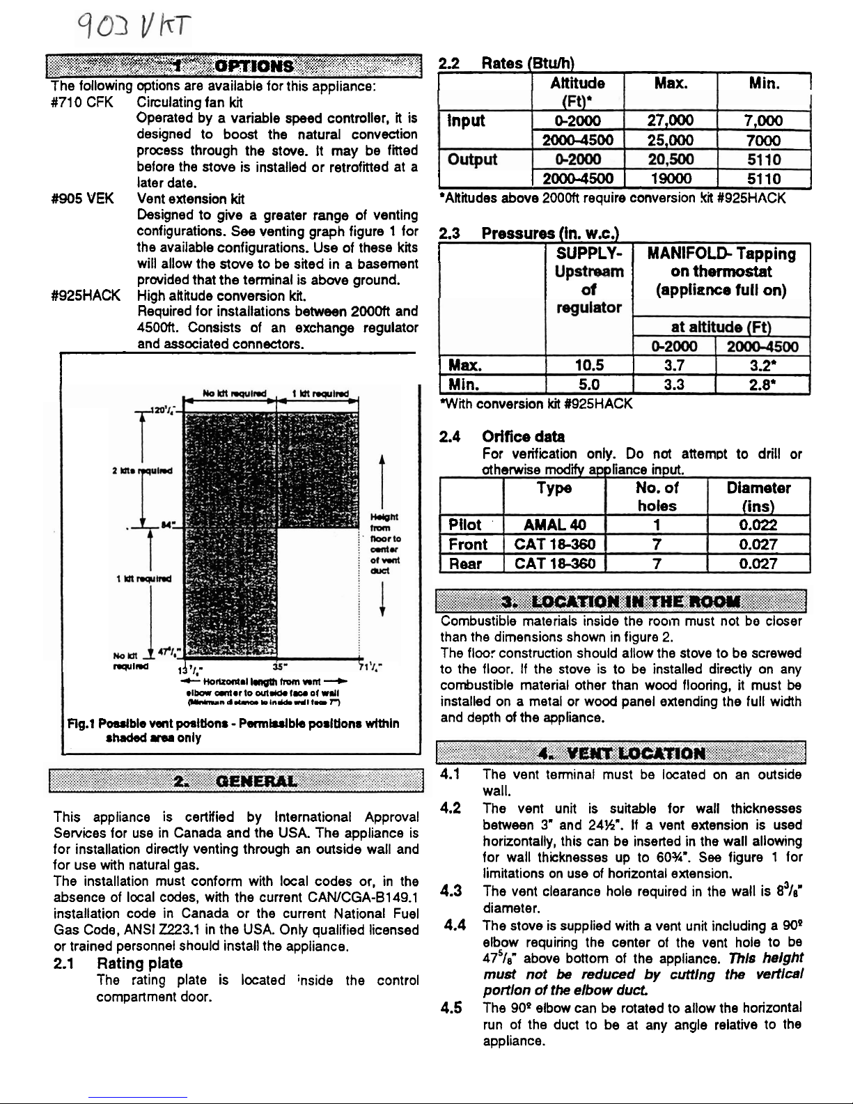
Designed to give a greater range of venting
configurations.
See
venting graph figure 1 for
the available configurations. Use of these
kits
will allow the stove to be sited in a basement
prwided that the terminal is abwe ground.
#925HACK High altitude conversion
ki.
Required for installations between
2000ft
and
4500ft. Consists of an exchange regulator
and associated connectors.
I
I=FJlna
14~1,-
*
Ho~al
fmm
nrd
-
eIba
marto
out&
fu
of
wdl
~nd.(mmln~dIlmaT)
Flg.1
Pdble
vent
posltlons - PwmhsJble
posltlons wlthln
shaded
m
only
This appliance is certified by International Approval
Services for use in Canada and the USA. The appliance is
for installation directly venting through an outside wall and
for use with natural gas.
The installation must conform with local codes or, in the
absence of local codes, with the current
CAWCGA-B149.1
installation code in Canada or the current National Fuel
Gas Code, ANSI
2223.1
in the USA. Only qualified licensed
or trained personnel should install the appliance.
2.1
Rating plate
The rating plate is located inside the control
compartment door.
2.2 Rates
(Btulh)
I
I
Altiiude
I
Max.
I
Min.
1
I
120004500
1
19000
1
5110
1
'Alitudes above 2000ft require conversion
kit
#925HACK
Input
2.3
Pressures (in.
w.c.)
I
I
SUPPLY- 1 MANIFOLD- Tapping
1
on thermostat
I
I
(appliance full on)
I
.
.
0-2000
20004500
I
MU.
I
10.5
1
3.7
I
3.2'
1
I
Min.
I
5.0
I
3.3 2.8'
With conversion
kit
#925HACK
27,000
25,000
2.4 Orifice data
For verification only. Do not attempt to drill or
7,000
7000
otherwise mdi appliance input.
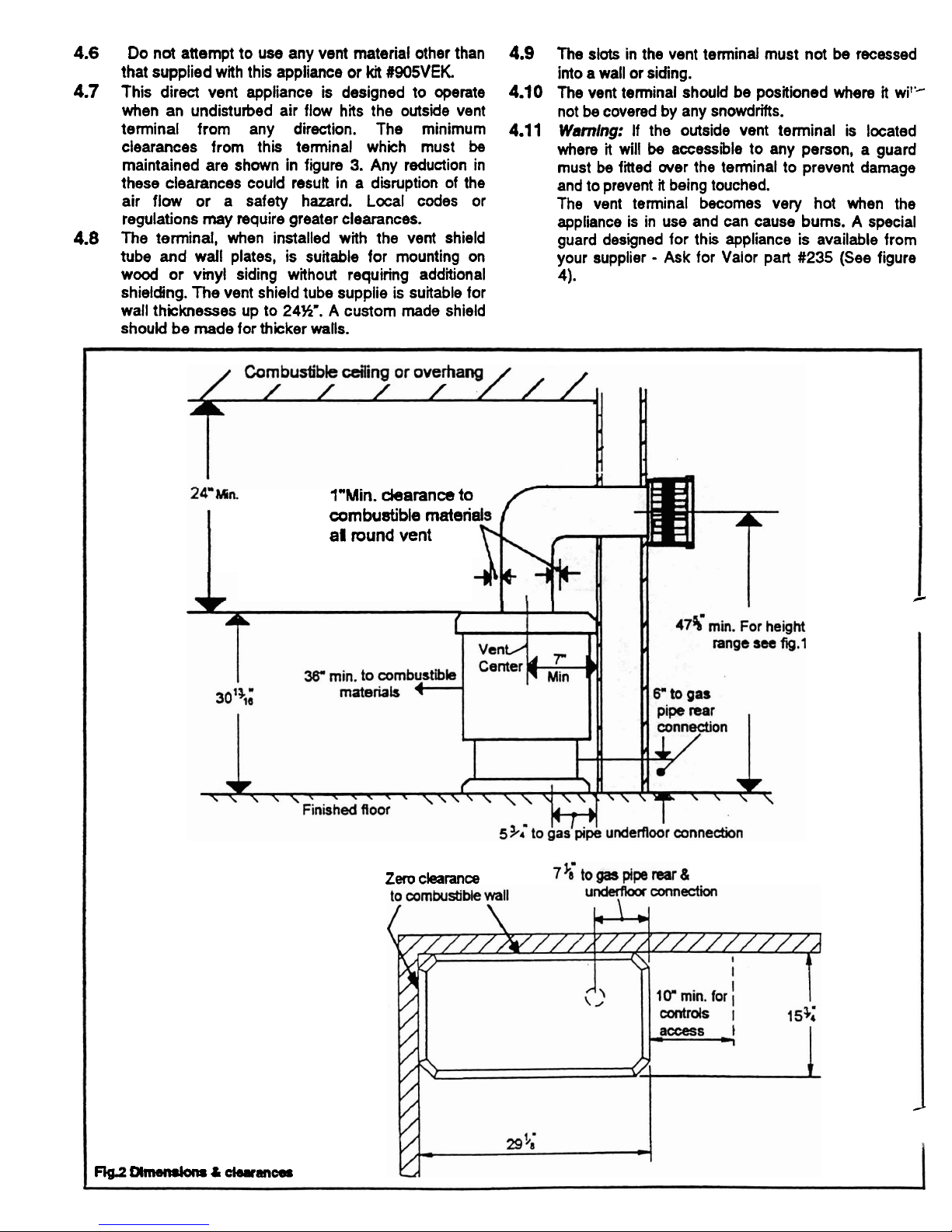
Combustible materials inside the rooln must not bo closer
than the dimensions shown in figure
2.
The floor construction should allow the stove to be screwed
to the
floor.
If
the stove is to be installed directly on any
combustible material other than wood flooring, it must
be
installed on a metal or wood panel extending the full width
and depth
of
the appliance.
Type
Pilot
'
Front
Rear
4.1
The vent terminal must be located on an outside
wall.
4.2
The vent unit is suit&le for wall thicknesses
between
3"
and
24%'.
If a vent extension is used
horizontally, this can be inserted in the wall allowing
for wall thicknesses up to 60%'.
See
figure 1 for
limitations on use of horizontal extension.
4.3
The vent clearance hole required in the wall is 8'/e9
diameter.
4.4
The stove is supplied with a vent unit including a 909
elbow requiring the center of the vent hole to be
475/8" above bottom of the appliance.
Thls
helght
must not
be
reduced
by
cutting
the
vertlcal
portlon of the
elbow
duct
4.5
The 909 elbow can be rotated to allow the horizontal
run of the duct to be at any
angle relative to the
appliance.
No. of
holes
AMAL40
CAT
18-360
CAT
18-360
Diameter
(ins)
1
7
7
0.022
0.027
0.027
4.6
Do not attempt to use any vent material other than
that supplied with this appliance or
kit
(1905VEK.
4.7
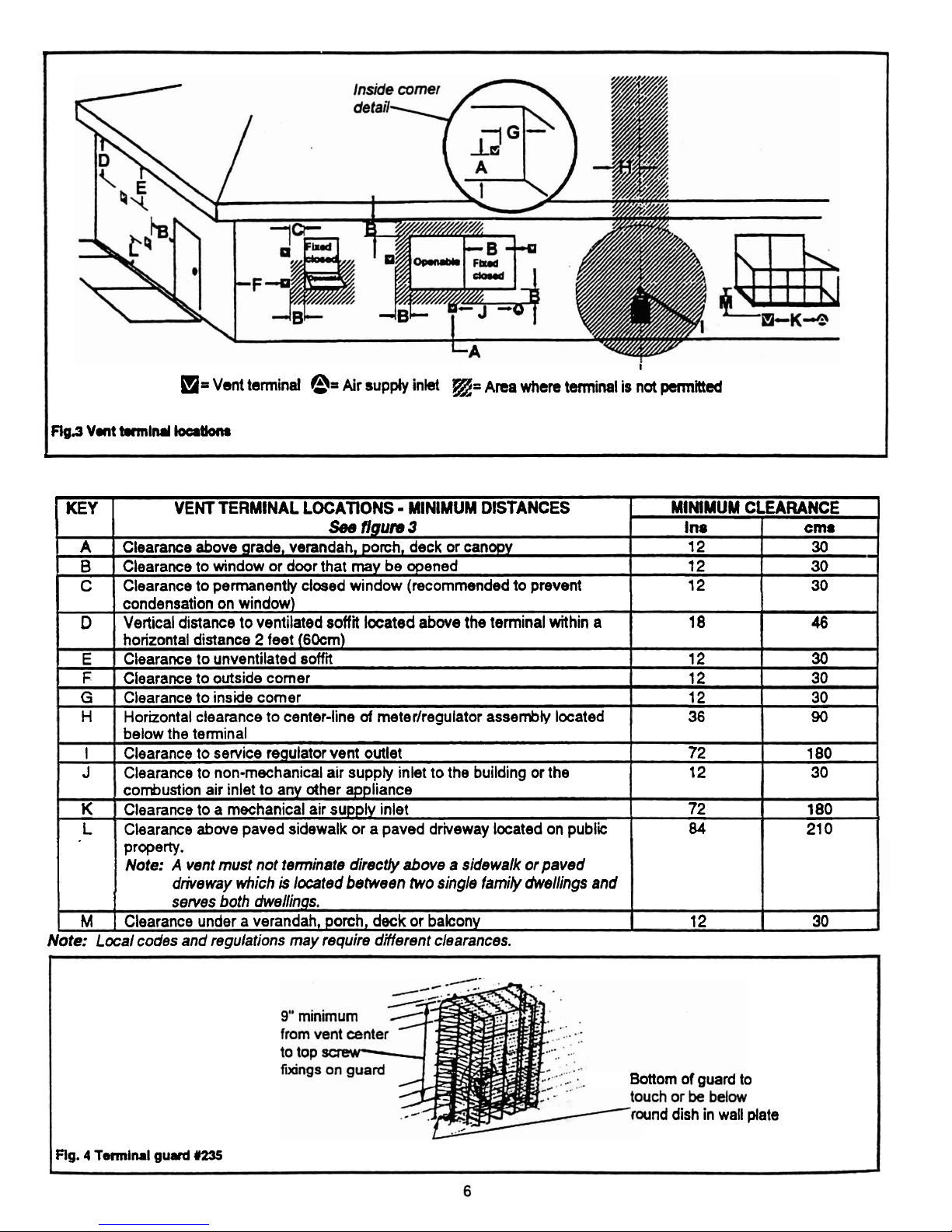
This direct vent appliance is designed to operate
when an undisturbed air flow hits the outside vent
terminal from any direction. The minimum
clearances from this terrninal which must
be
maintained are shown in figure
3.
Any reduction in
these clearances could
resutt in a disruption of the
air flow or a safety hazard. Local codes or
regulations
may
require greater clearances.
4.8
The terminal, when installed with the vent shield
tube and wall plates, is suitable for mounting on
wood or vinyl siding without requiring additional
shielding. The vent shield tube supplie is suitable for
wall thicknesses up to
24%.
A custom made shield
should be made for thicker walls.
-
4.9
The slots in the vent terminal must not be recessed
into a wall or siding.
4.10
The vent terminal should be positioned where
it
wit'
not be covered by any snowdrifts.
4.11
Wamlng:
If the outside vent terminal is located
where
it
will
be
accessible to any person, a guard
must
be
fied wer the terminal to prevent damage
and to prevent it being touched.
The vent terminal becomes very hot when the
appliance is in use and can cause bums. A special
guard designed for this appliance is available from
your supplier
-
Ask for Valor part
#235
(See figure
4).
lUMin.
clearance
to
combustible materia
al
round
vent
/
Zero
clearance
/
FIg.2U~&clsran~
b
I
m=
Vent tennind
@=
Air supply inkt
@=
Area where
t-inal is not
permitted
mga
vat
brm~rul
loeruona
.
1
KEY
I
VENT TERMINAL LOCATIONS - MINIMUM DISTANCES
1
MINIMUM CLEARANCE
1
I
condensation'on windowj
I
I
D
I
Vertical distance to ventilated soffit located above the terminal within
a
I
18 46
A
B
C
~ee
ngum
3
Clearance above grade, verandah, porch, deck or canopy
Clearance to window or
door that may be opened
Clearance to permanently closed window
(recommended to prevent
E
F
G
H
I
J
I
I
property.
Note: A vent must not terminate directly above a sidewalk or paved
driveway which
is
located between two single family dwellings and
Ins
12
12
12
horizontal distance 2 feet (60cm)
Clearance to unventilated
soffit
Clearance to outside comer
Clearance to inside comer
Horizontal clearance to center-line
of
meterlregulator assembly located
K
L
I
serves both dwellings.
I
I
M
1
Clearance under a verandah, porch, deck or balcony
12
30
Note:
Local codes and regulations may require different clearances.
cms
30
30
30
-
below the terminal
Clearance to service regulator vent outlet
Clearance to non-mechanical air supply inlet to the building or the
Bottom of guard to
und dish in wall plate
Rg. 4 Tennlml
gurvd
#ZS
12
12
12
36
combustion air inlet to any other appliance
Clearance to a mechanical air supply inlet
Clearance
abwe paved sidewalk or a paved driveway located on public
30
30
30
90
72
12
180
30
72
84
180
21 0
 Loading...