

Valor 910 Brunswick Installer And Owner Manual

© GDC Group Ltd. 2014
08/52706/0
Brunswick
Model 910
GAS STOVE
Fitted with a Ceramic Coal fuel effect.
INSTALLER AND OWNER GUIDE
INSTALLER: Please leave this guide with the owner
We trust that this guide gives
sufficient details to enable this
appliance to be installed, operated
and maintained satisfactorily.
However, if further information is
required, our
Valor Fires Technical Helpline will
be pleased to help.
Telephone 0844 879 35 88 (National
call rates apply in the United
Kingdom).
In the Republic of Ireland
Telephone 01 842 8222.

© GDC Group Ltd.
All rights reserved. No part of this publication may be reproduced in any material form
(including photocopying), stored in any medium by electronic means (including in any
retrieval system or database) or transmitted, in any form or by any means, whether
electronic, mechanical, recording or otherwise, without the prior written permission of
the copyright owner.
Applications for the copyright owner's permission to reproduce any part of this
publication should be made, giving details of the proposed use, to the following
address: The Marketing Communications Manager, GDC Group Ltd, Millbrook House,
Grange Dive, Hedge End, Southampton, SO30 2DF.
Warning: Any person who does any unauthorised act in relation to a copyright work
may be liable to criminal prosecution and civil claims for damages.
Because our policy is one of constant development and improvement, details may vary
slightly from those given in this publication
Page 2
© GDC Group Ltd. 2014
THIS APPLIANCE IS FOR USE WITH NATURAL GAS (G20).
WHEN CONVERTED USING CONVERSION KIT NO. 0591011 THIS APPLIANCE
IS FOR USE WITH PROPANE GAS (G31).
THIS APPLIANCE IS SUITABLE ONLY FOR INSTALLATION IN THE UNITED
KINGDOM (GB) AND THE REPUBLIC OF IRELAND (IE).

Page 3
INSTALLER GUIDE
© GDC Group Ltd. 2014
INSTALLER GUIDE
FOR OWNER GUIDE SEE PAGES 19 TO 30

Page 4
© GDC Group Ltd. 2014
LIST OF CONTENTS
Section Heading Page
INSTALLER GUIDE 3 - 18
OWNER GUIDE 19 - 30
1. SAFETY 5
2. APPLIANCE DATA AND EFFICIENCY 6
General information. 6
Efficiency. 6
3. UNPACKING 7
4. STOVE SET UP 8
Legs and lower casting cover 8
Flue collar, diverter box, flue spigot and flue restrictor plate. 8
Down draught deflector. 9
Burner module and rear burner support fitment. 10
Thermal switch. 10
Diverter box. 10
5. GENERAL INSTALLATION REQUIREMENTS 11
Regulations, Standards and Law. 11
The Hearth. 11
Clearances. 12
Flue / Chimney. 12
Ventilation. 13
Location. 13
Propane gas. 13
Gas connection. 13
Securing the stove. 13
Fitting the ceramic fuel effect. 14
6. OPERATING THE STOVE 14
Pre-lighting checks. 14
Lighting the burner. 14
Operating the burner. 14
Inlet pressure check. 15
Check for spillage. 15
Flame supervision and spillage monitoring system. 15
7. FINAL REVIEW AND SERVICING 16
Final Review. 16
Servicing. 17
Checking the aeration setting of the burner. 18
INSTALLER GUIDE

1. SAFETY
This product uses fuel effect pieces containing Refractory Ceramic Fibres
(RCF), which are man-made vitreous silicate fibres. Excessive exposure to
these materials may cause irritation to eyes, skin and respiratory tract.
Consequently, it is important to take care when handling these articles to
ensure that the release of dust is kept to a minimum. To ensure that the release
of fibres from these RCF articles is kept to a minimum, during installation and
servicing we recommend that you use a HEPA filtered vacuum to remove any
dust and soot accumulated in and around the stove before and after working on
the stove. When replacing these articles we recommend that the replaced items
are not broken up, but are sealed within a heavy duty polythene bag, clearly
labelled as RCF waste. RCF waste is classed as a stable, non-reactive
hazardous waste and may be disposed at a landfill licensed to accept such
waste. Protective clothing is not required when handling these articles, but we
recommend you follow the normal hygiene rules of not smoking, eating or
drinking in the work area and always wash your hands before eating or
drinking. This appliance does not contain any component manufactured from
asbestos or asbestos related products.
Installer
Valor stoves are efficient appliances giving off convected, conducted and radiated
heat. All the surfaces of the stove - except the controls - are working surfaces and
become hot in use. They must not be touched or have any combustible objects or
materials placed on or near them. A fire guard complying with BS 8423 should be
fitted for the protection of young children, the elderly, the infirm or pet animals.
The appliance is fitted with a flue safety device. If the appliance closes down after a
period of operation for no apparent reason, the consumer should be informed to stop
using the appliance until the installation and appliance have been thoroughly
checked. Under no circumstances should the flue safety device be altered or
bypassed in any way. Only a genuine manufacturers replacement part should be
fitted.
Before continuing any further with the installation of this appliance please read the
following guide to manual handling:
- The lifting weight of this appliance is 55 kg. We therefore recommend that two
people should be sufficient to lift the stove. If fitting or moving the stove alone we
recommend the use of suitable lifting apparatus.
- When lifting always keep your back straight. Bend your legs and not your back.
- Avoid twisting at the waist. It is better to reposition your feet.
Page 5
© GDC Group Ltd. 2014
INSTALLER GUIDE

- Avoid upper body/top heavy bending. Do not lean forward or sideways whilst
handling the stove.
- Always grip with the palm of the hand. Do not use the tips of fingers for support.
- Always keep the stove as close to the body as possible. This will minimise the
cantilever action.
- Use gloves to provide additional grip.
- Always use assistance if required.
2. APPLIANCE DATA AND EFFICIENCY
General information.
*When converted using kit 0591011.
The appliance information label is located on a plate at the base of the stove.
Efficiency.
The efficiency of this appliance has been measured as specified in BS EN 613 and
the result is as below :
Model
Efficiency % (Gross)
910 73.1
910 when converted to LPG. 73.1
Page 6
© GDC Group Ltd. 2014
Gas Natural (G20) Propane (G31) *
Inlet Pressure 20mbar 37mbar
Input - Max. (Gross) 5.50kW (18,766Btu/h) 5.4kW (18,425Btu/h)
Input - Min. (Gross) 2.3kW (7,850 Btu/h) 3.8kW (12,965Btu/h)
Inlet Test Pressure (Cold)
20.0 ± 1.0mbar
(8.0 ± 0.4in w.g.)
37.0 ± 1.0mbar
(14.85 ± 0.4in w.g.)
Gas Connection 8mm pipe 8mm pipe
Burner Injector Cat 82 - 065 Size 116
Pilot
Copreci Ref. O.D.S
21500/212
Copreci Ref. O.D.S
21500/212 Fitted with RBM
180 -02 injector
Ignition
Piezo Electric. Integral with
Gas Tap
Piezo Electric. Integral with
Gas Tap
Aeration See page 18 Non-adjustable
INSTALLER GUIDE
The gross calorific value of the fuel has been used for this efficiency calculation. The
test data from which it has been calculated has been certified by BSI.
The efficiency value may be used in the UK Government's Standard Assessment
Procedure (SAP) for energy rating of dwellings.
The conversion of net efficiency to gross was achieved by multiplying the net
efficiency by the following conversion factor from Table E3 of SAP 2005, rounding
down to the nearest whole number.
3. UNPACKING
Before installation, check that the following components, where required, have been
delivered.
Loose parts box - Contains the flue spigot, four feet, lower front panel,
restrictor plate and touch up paint.
+
Accessory Pack - Contains bolts, nuts, washers, wall plugs and screws.
Ceramic box - Contains ceramic coal set.
Stove Burner Assy box - Contains 910 burner module including rear burner
support & knob assy. Item number 05910X1.
Inside Stove Casting - Contains the down draught deflector and diverter box.
Page 7
© GDC Group Ltd. 2014
Gas Conversion factor from net to gross efficiency
Natural Gas 0.901
LPG 0.921
INSTALLER GUIDE
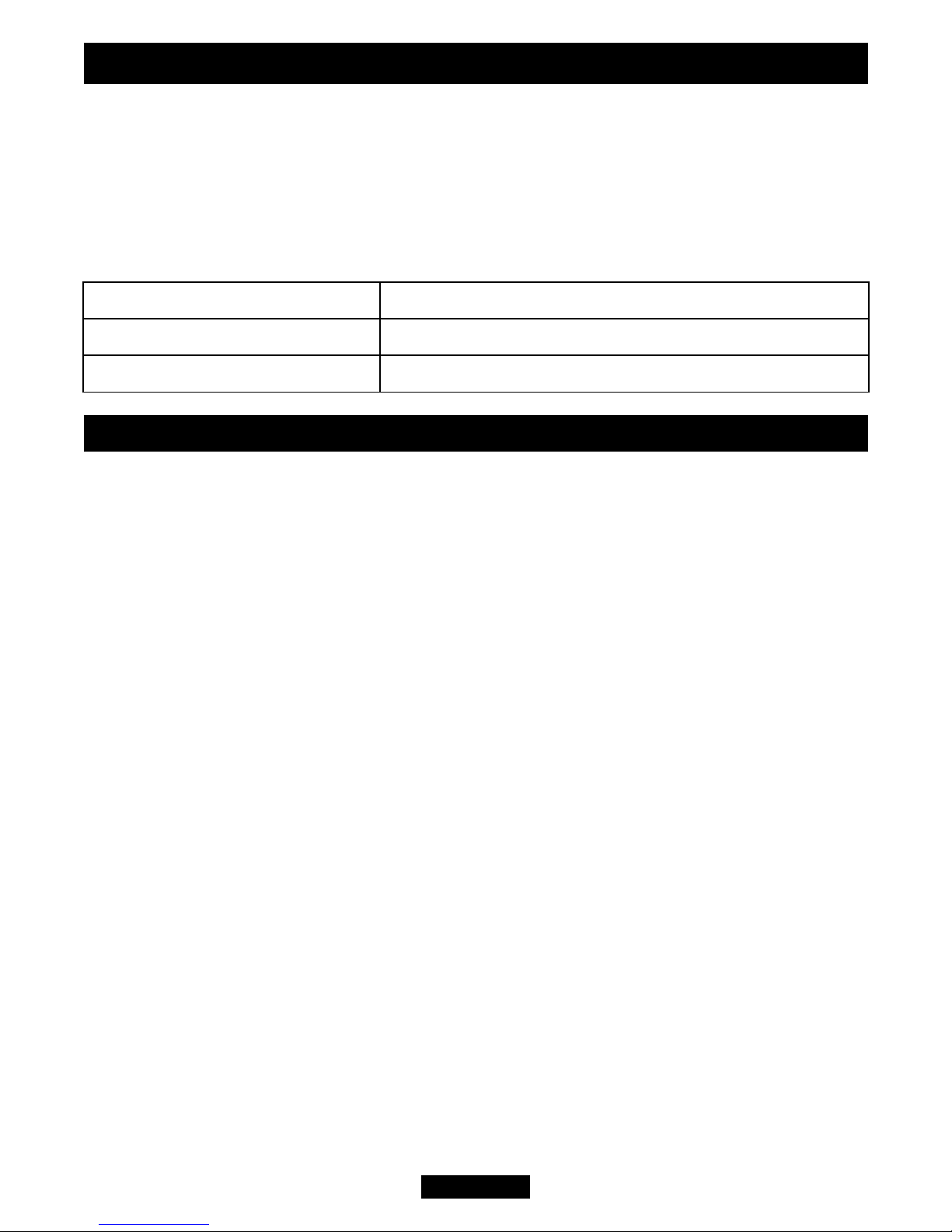
NOTE: The door is secured with a locking bolt and Hex nut. To open the door use a
3mm Allen key to loosen the hex nut on the side of the door, being carefull not to
remove it completely. Ref to Figure A below. Then select a suitably sized spanner and
turn counter clockwise by approximately a quarter turn on the handle to open.
4. STOVE SET UP
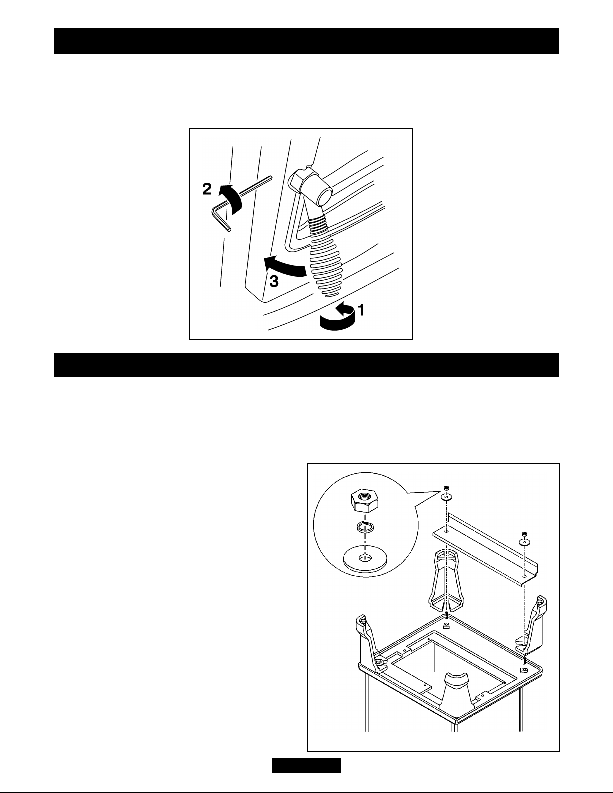
Legs and lower front panel cover (See figure 1).
- Locate the four leg securing studs into the four holes in the base of the body.
- Locate the four legs to the underside of the casting body. There are two feet with
holes in the base. We recommend that these be placed at the rear of the stove.
- Place the front panel cover on top of the front legs.
- Secure the legs and front panel cover to
the underside of the casting body using
the nuts and washers supplied.
Flue collar, diverter box, flue spigot and
flue restrictor plate.
- These should be located to the stove as
in figure 2. Do not bolt in place until fitting
the deflector. The flue restrictor is for use
where the flue draught is excessive. The
flue spigot is screwed to the cast flue
collar and clamps the flue restrictor plate
in place (See figure 2).
There may however, be certain
circumstances where fitting the restrictor
causes the fire to fail the spillage test. In
such cases the restrictor will have to be
removed. After removal conduct the
spillage check again.
Page 8
© GDC Group Ltd. 2014
Figure 1.
INSTALLER GUIDE
Figure A.
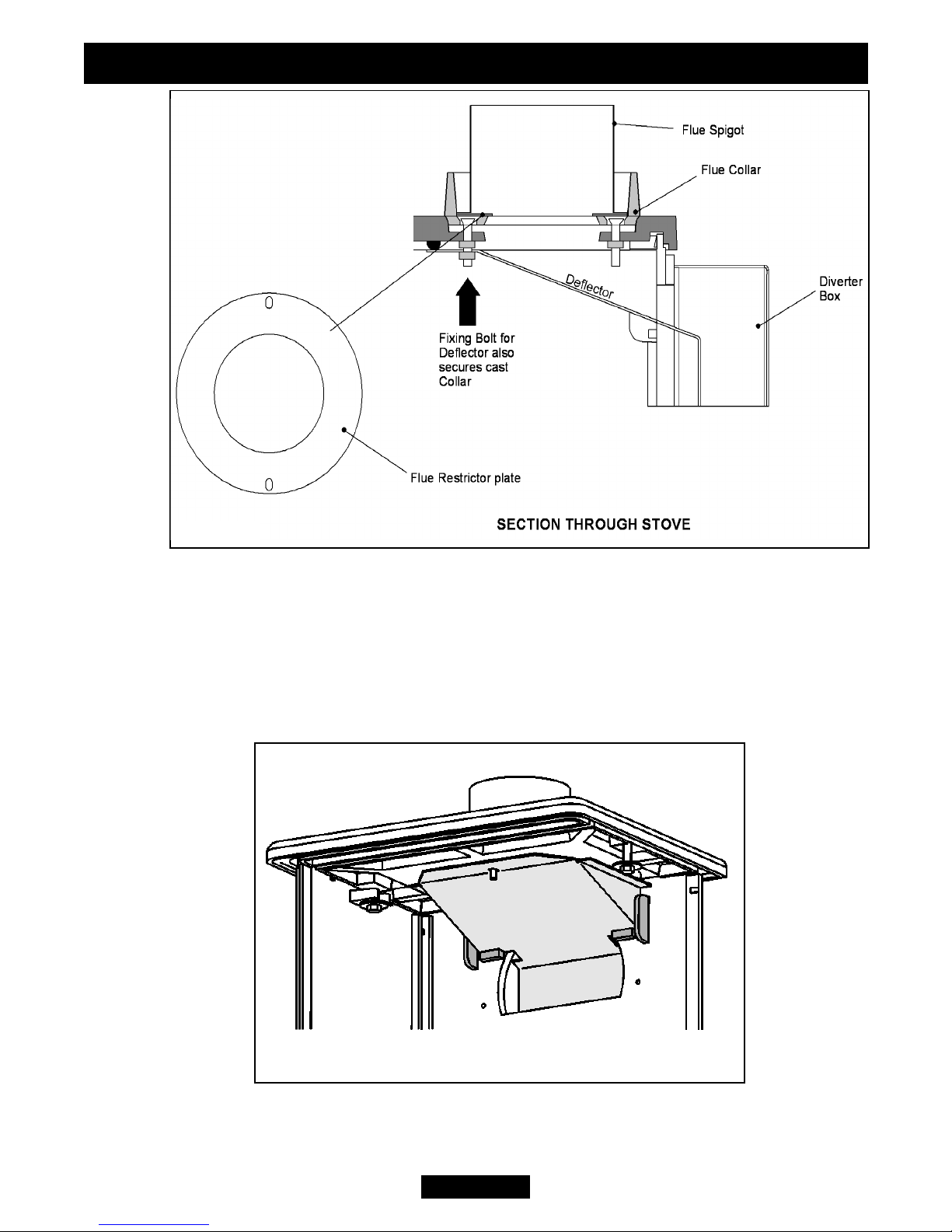
Down draught deflector.
- The down draught deflector is secured in place using the upper front bolt and nut
that secure the cast collar to the outside of the cast body. Unscrew and remove the
nut and washer from inside the top of the casting body. Position the down draught
deflector as in figure 3. It MUST be sealed against the top of the stove casting. It is
important that it sits on top and between the raised cast areas on the rear of the stove
body (See figure 3). Secure in place using the nut and washer removed previously.
Page 9
© GDC Group Ltd. 2014
Figure 2.
INSTALLER GUIDE
Figure 3.
 Loading...