

Valor 739IRN, 739IRP, Legend 739IRN, Legend 739IRP Installation And Owner's Manual
LEGEND
DV Gas Insert (Rocks)
739IRN (NG) & 739IRP (LPG)
Installation and Owner’s Manual
INSTALLER
HOT GLASS WILL
CAUSE BURNS.
DO NOT TOUCH GLASS
UNTIL COOLED.
NEVER ALLOW CHILDREN
TO TOUCH GLASS.
WARNING: If the information in these
instructions is not followed exactly, a fi re
or explosion may result causing property
damage, personal injury or loss of life.
Do not store or use gasoline or other
fl ammable vapors and liquids in the vicinity
of this or any other appliance.
WHAT TO DO IF YOU SMELL GAS
• Do not try to light the appliance.
• Do not touch any electrical switch; do not
use any phone in your building.
• Immediately call your gas supplier from
a neighbor’s phone. Follow the gas
supplier’s instructions.
• If you cannot reach your gas supplier, call
the fi re department.
Installation and service must be performed
by a qualifi ed installer, service agency or the
gas supplier.
Leave this manual
with the appliance.
CONSUMER
Retain this manual
for future reference.
Please read this manual BEFORE installing
and operating this appliance.
This appliance may be installed in an
after-market permanently located,
manufactured (mobile) home where not
prohibited by local codes.
This appliance is only for use with the type
of gas indicated on the rating plate. This
appliance is not convertible for use with
other gases, unless a certifi ed kit is used.
This appliance is a domestic room-heating
appliance. It must not be used for any other
purposes such as drying clothes, etc.
This appliance is suitable for installation in a
bedroom or bed sitting room.
Massachusetts: The piping and fi nal
gas connection must be performed by a
licensed plumber or gas fi tter in the State of
Massachusetts.
Ce guide est disponible en français sur demande.
4001514-08
©2011, Miles Industries Ltd.
Manufactured by
MILES INDUSTRIES LTD., British Columbia, Canada
www.valorfi replaces.com
Thank You ...
For purchasing a Valor by Miles Industries. Your new radiant gas heater is a technical
appliance that must be installed by a qualifi ed dealer. Each Valor fi replace is fully
tested during the production process for your safety and comfort.
Your unit has been professionally installed by:
Dealer Name _______________________________________
Phone Number ______________________________________
Should you encounter an operational problem, call your dealer immediately.
Do not try to repair the unit as you may cause an injury or damage the fi replace.
The information contained in this installation manual is believed to be correct at
the time of printing. Miles Industries Ltd. reserves the right to change or modify any
information or specifi cations without notice. Miles Industries Ltd. grants no warranty,
implied or stated, for the installation or maintenance of your heater, and assumes no
responsibility for any consequential damage(s).
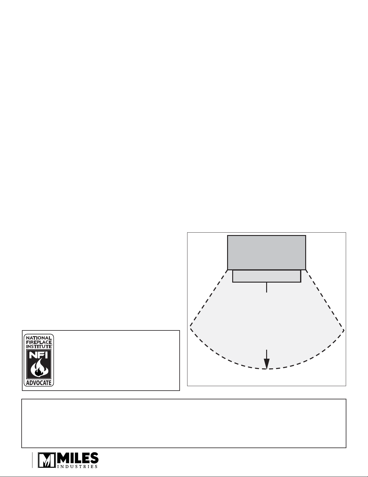
Fireplace
Do not put
furniture or other objects
in this space in front of
We recommend that our gas
hearth products be installed
and serviced by professionals
who are certifi ed in the United
States by NFI (National Fireplace
Institute®).
Designed and Manufactured by / for
Miles Industries Ltd.
190–2255 Dollarton Highway, North Vancouver, BC, CANADA V7H 3B1
Tel. 604-984-3496 Fax 604-984-0246
www.valorfi replaces.com
© Copyright Miles Industries Ltd., 2011.
the replace:
36” (0.9 m)
Hearth
2
Safety and Your Fireplace
Safety and Your Fireplace
Please Read and Carefully Follow all Safety Warnings and
Operating Instructions Contained in Your Owners Manual
(Replacement Manuals are available by contacting our service department at
1-800-468-2567 or visit www.valorfi replaces.com).
Please Follow These Important
Child Safety Precautions and
Recommendations,
• Parts of your Valor Fireplace become
extremely hot while in operation.
• The glass viewing window
temperature can
exceed 500 F
at full capacity.
Momentary contact
with a hot glass
surface can cause
a severe burn, even if the fi replace
is operating at reduced heating
capacity.
• The glass window will remain hot
for an extended period of time after
the fi replace has been turned off.
Ensure that children are prevented
from touching the fi replace during the
cool down period.
withdraw in the event of accidental
contact with a hot surface.
• A physical barrier is strongly
recommended if there are young
children, or at-risk individuals in the
house. Install an approved aftermarket safety gate to keep toddlers,
young children and other at-risk
individuals a safe distance from the
fi replace.
• Keep the remote control handset
out of reach of children at all
times. A wall mount storage holster
is provided with your remote control
handset.
• Ensure that the fi replace, including
the pilot light, is completely turned
off when children are present and
close supervision and safety barriers
are not available—see page 23 of
Owner’s Information section.
• Toddlers and Y oung Children
must be closely supervised at all
times when they are in the same
room as the operating fi replace. They
lack full awareness of danger and
rely on your protection. Toddlers,
in particular, do not have the motor
skills and response refl exes to
• If the fi replace is not going to be used
for the summer or any extended
period of time, remove the batteries
from the remote control handset
and receiver. It is recommended that
batteries are replaced annually in any
event—see page 22.
3

Table of Content
Safety and Your Fireplace .............................................................................3
◊
Safety and Warning Information...................................................................5
Specifi cations ................................................................................................6
Overview .........................................................................................................7
Dimensions ....................................................................................................8
Cavity ..............................................................................................................8
Clearances ......................................................................................................9
Venting ..........................................................................................................10
Installation Planning ....................................................................................11
Existing Fireplace Preparation ...................................................................11
Appliance Preparation .................................................................................12
Supply Gas Installation ...............................................................................15
Ceramic/Enamel Panels Installation ..........................................................16
Ceramic Rocks Installation .........................................................................17
Window Refi tting .........................................................................................19
Remote Control Initial Set-up .....................................................................19
Operation Check & Aeration Settings Adjustment ...................................20
Remote Control Handset Wall Holder Installation ....................................20
Owner’s Information ....................................................................................21
◊
Remote Control Operation ..........................................................................24
Options .........................................................................................................27
Lighting Instructions ...................................................................................28
Wiring Diagram ............................................................................................29
Venting Accessories ....................................................................................30
Warranty .......................................................................................................31
◊
Spare Parts ...................................................................................................32
= Updated content
◊
4

Safety and Warning Information
OWNER’S INFO
READ and UNDERSTAND all instructions carefully
before starting the installation. FAILURE TO FOLLOW
these installation instructions may result in possible fi re
hazard and will void the warranty.
Prior to the fi rst fi ring of the fi replace, READ the
Owner’s Information section of this manual.
DO NOT USE this appliance if any part has been under
water. Immediately, CALL a qualifi ed service technician
to inspect the unit and to replace any part of the control
system and any gas control that has been under water.
THIS UNIT IS NOT FOR USE WITH SOLID FUEL.
Installation and repair should be PERFORMED by a
qualifi ed service person. The appliance and venting
system should be INSPECTED before initial use and at
least annually by a professional service person. More
frequent cleaning may be required due to excessive
lint from carpeting, bedding, etc. It is IMPERATIVE that
the unit’s control compartment, burner, and circulating
air passageways BE KEPT CLEAN to provide for
adequate combustion and ventilation air.
Always KEEP the appliance clear and free from
combustible materials, gasoline, and other fl ammable
vapors and liquids.
NEVER OBSTRUCT the fl ow of combustion and
ventilation air. Keep the front of the appliance CLEAR
of all obstacles and materials for servicing and proper
operation.
Due to the high temperature, the appliance should be
LOCATED out of traffi c areas and away from furniture
and draperies. Clothing or fl ammable material SHOULD
NOT BE PLACED on or near the appliance.
Children and adults should be ALERTED to the hazards
of high surface temperature and should STAY AWAY to
avoid burns or clothing ignition.
YOUNG CHILDREN should be CAREFULLY
SUPERVISED when they are in the same room as
the appliance. Toddlers, young children and others
may be susceptible to ACCIDENTAL CONTACT
BURNS. A physical barrier is recommended if there
are at risk individuals in the house. To restrict access
to a fi replace or stove, INSTALL AN ADJUSTABLE
SAFETY GATE to keep toddlers, young children and
other at risk individuals out of the room and away from
hot surfaces.
This unit MUST be used with a vent system as
described in this installation manual. NO OTHER vent
system or components MAY BE USED.
This gas fi replace and vent assembly MUST be vented
directly to the outside and MUST NEVER be attached
to a chimney serving a separate solid fuel burning
appliance. Each gas appliance MUST USE a separate
vent system. Common vent systems are PROHIBITED.
INSPECT the external vent cap on a regular basis to
make sure that no debris, plants, trees, shrubs are
interfering with the air fl ow.
The glass door assembly MUST be in place and sealed
before the unit can be placed into safe operation.
DO NOT OPERATE this appliance with the glass door
removed, cracked, or broken. Replacement of the glass
door should be performed by a licensed or qualifi ed
service person. DO NOT strike or slam the glass door.
The glass door assembly SHALL ONLY be replaced
as a complete unit, as supplied by the fi replace
manufacturer. NO SUBSTITUTE material may be used.
DO NOT USE abrasive cleaners on the glass door
assembly. DO NOT ATTEMPT to clean the glass door
when it is hot.
TURN OFF the gas before servicing this appliance.
It is recommended that a qualifi ed service technician
perform an appliance check-up at the beginning of each
heating season.
Any safety screen or guard removed for servicing
MUST BE REPLACED before operating this appliance.
DO NOT place furniture or any other combustible
household objects within 36” of the fi replace front.
BE CAREFUL not to put any decorating objects
sensitive to heat to close above or around the fi replace
as it gets very hot when operating.
DO NOT use this heater as a temporary source of heat
during construction.
This appliance is a DOMESTIC ROOM-HEATING AP-
PLIANCE. It must not be used for any other purposes
such as drying clothes, etc.
State of California. Proposition 65 Warning. Fuels
used in gas, wood-burning or oil fi red appliances,
and the products of combustion of such fuels, contain
chemicals known to the State of California to cause
cancer, birth defects and other reproductive harm.
California Health & Safety Code Sec. 25249.6.
5
OWNER’S INFO
Safety and Warning Information
Operating your fi replace for the fi rst time
When operating your new fi replace for the fi rst time,
some vapors may be released due to the burning of
curing compounds used in the manufacture of the
appliance. They may cause a slight odor and could
cause the fl ames to be the full height of the fi rebox, or
even slightly higher, for the fi rst few hours of operation.
Specifi cations
Approval & Codes
This appliance is certifi ed to ANSI Z21.88-2009 / CSA
2.33-2009 American National Standard / CSA Standard
for Vented Gas Fireplace Heaters for use in Canada
and USA, and to CGA 2.17-91 High Altitude Standard
in Canada. This appliance is for direct vent insert
installations.
This appliance complies with CSA P4.1-09 Testing
method for measuring annual fi replace effi ciencies.
The installation must conform to local codes or, in the
absence of local codes, with the National Fuel Gas
Code, ANSI Z223.1 or the Natural Gas and Propane
Installation Code CAN/CGA-B149. Only qualifi ed
licensed or trained personnel should install this
appliance.
This appliance must be electrically grounded in
accordance with local codes, or, in the absence of local
codes, with the National Electrical Code, ANSI/NFPA
70 or the Canadian Electrical Code, CSA C22.1.
Ratings
It is also possible that these vapors could set off any
smoke detection alarms in the immediate vicinity.
These vapors are quite normal on new appliances. We
recommend opening a window to vent the room. After
a few hours use, the vapors will have disappeared and
the fl ames will be at their normal height.
*High Altitude Installations
Input ratings are shown in BTU per hour and are
certifi ed without deration for elevations up to 4,500 feet
(1,370 m) above sea level.
For elevations above 4,500 feet (1,370 m) in USA,
installations must be in accordance with the current
ANSI Z223.1 and/or local codes having jurisdiction.
Heating value of gas in some areas is reduced to
compensate for elevation—consult your local gas utility
to confi rm.
For installations at elevations above 4,500 feet
(1,370 m) in Canada, please consult provincial and/or
local authorities having jurisdiction.
Supply Gas
Heater engine 739IRN is used with natural gas.
Heater engine 739IRP is used with propane gas.
The supply pressure must be between the limits shown
in the Ratings section above.
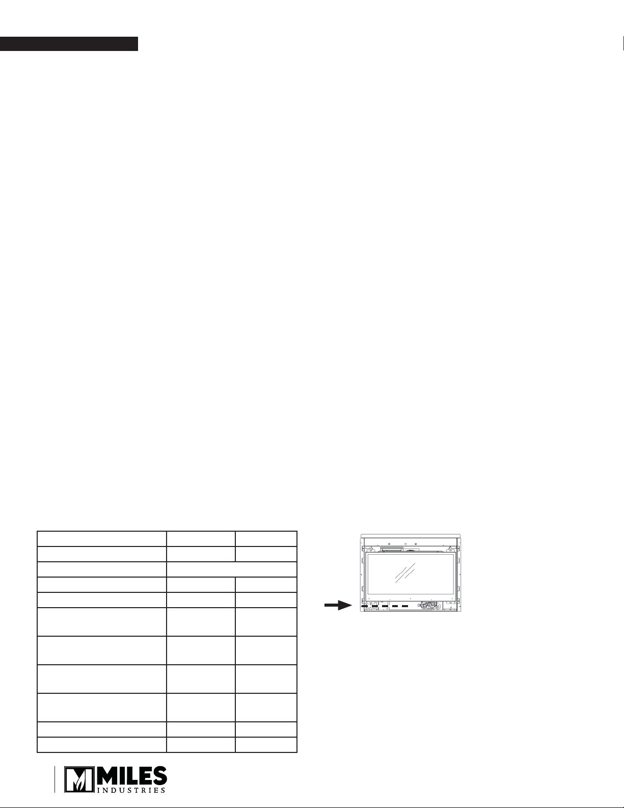
The supply connection is 3/8” NPT female and located
on the left hand side of the control valve. The gas line
entry point is on the left hand side on the fi replace.
Model NG LPG
Gas Natural Propane
Altitude (Ft.)* 0-4,500 feet*
Input Maximum (Btu/h) 26,000 24,000
Input Minimum (Btu/h) 6,500 13,000
Manifold Pressure (in
w.c.)
Minimum Supply
Pressure (in w.c.)
Maximum Supply
Pressure (in w.c.)
Main Burner Injector
Marking
Pilot Injector Marking 35 27
Min. Rate By-Pass Screw 125 125
3.6 10.0
5.0 11.0
10.0 14.0
82-750 92-260
6
X
X
Conversion Kits
The 739IR Legend G3 is supplied as natural gas or
propane gas and is fi eld convertible between fuels. See
instructions packaged with the conversion kit for further
information.
Electrical
The 739 does not require an electrical power source to
operate as a heater. However, if the appliance is fi tted
with a fan, a grounded power source is required.
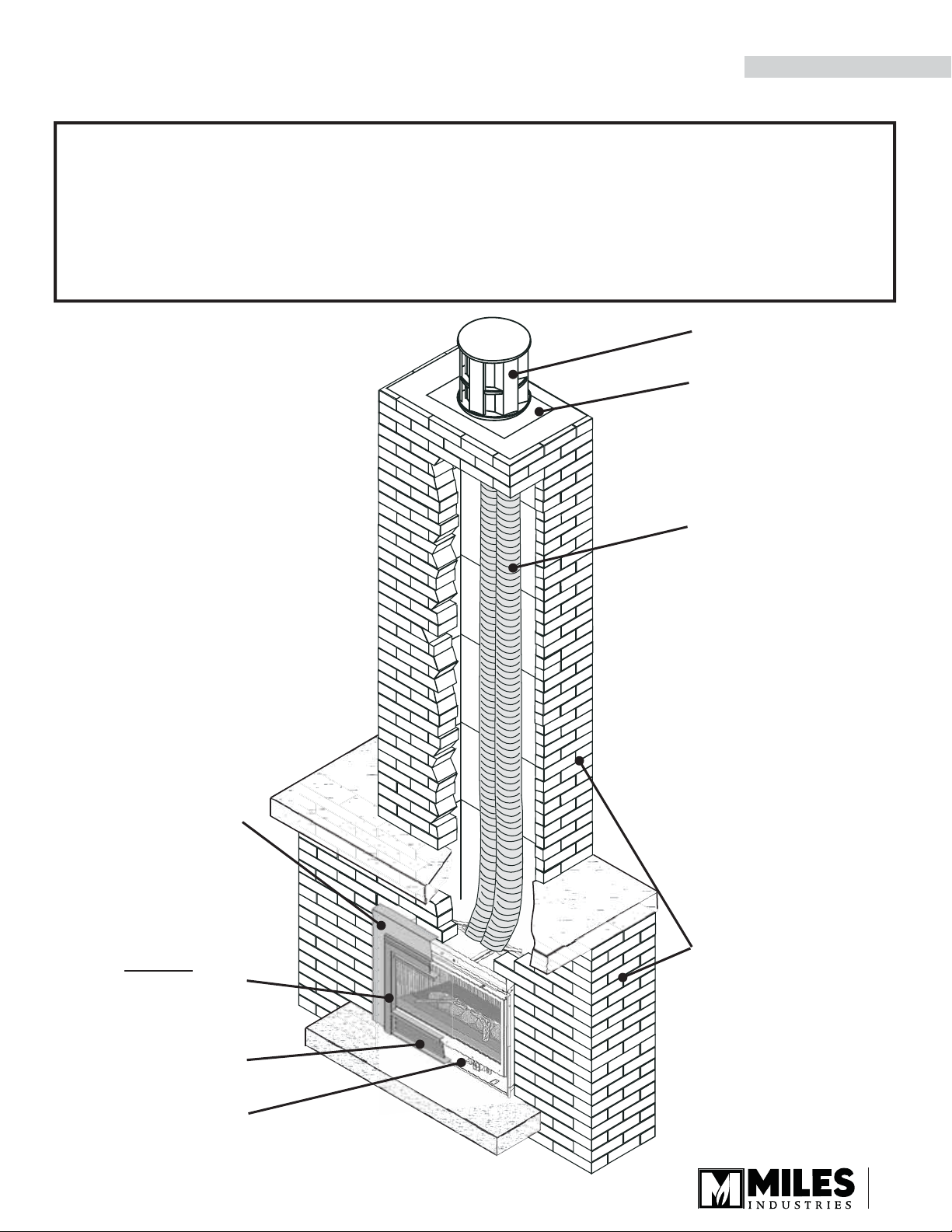
Overview
INSTALLATION
This appliance may ONLY be installed in an existing unaltered,
functioning solid-fuel burning fi replace with a working fl ue and
constructed of non-combustible material.
DO NOT install into combustible construction. This appliance
is NOT APPROVED for installation with a zero clearance kit.
Chimney Terminal Cap
Flashing
2 x 3” approved
fl ex chimney liners
running full length
Outer trim
(optional, sold
separately)
Inner Front
(required, sold
separately)
Fret
(optional, sold
separately)
739IR fi replace
Existing unaltered,
functioning solidfuel burning
fi replace & chimney
7
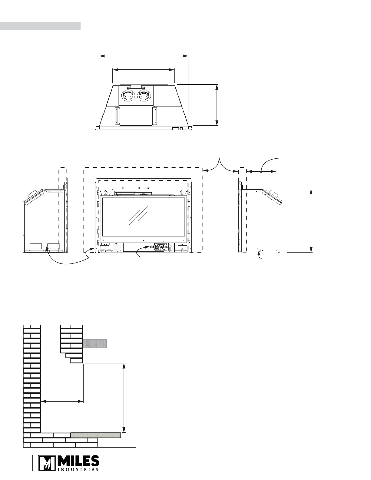
INSTALLATION
Dimensions
28-5/8” (727 mm)
19-1/2” (495 mm)
12” (305 mm)
or 12-5/8” (321 mm)
Varies with
outer trim options
Optional Outer Trim or
Surround sold separately
9-3/8” (238 mm)
or 10” (254 mm)
Varies with
outer trim options
20”
(508 mm)
Gas inlet Gas connection
Electrical inlet
Cavity
Check that masonry step does not interfere with install dimensions or
vent pipe.
If mantel is combustible, see section Clearances for allowable
clearances.
Minimum width of fi replace opening at front: 28” (711 mm)
X = 12” (305 mm) or 12-5/8” (321 mm)—varies with outer trim options
X
Y = 20” (508 mm)
Y
8
HOT HEARTH!
The hearth in front of the fi replace
becomes very hot when the fi replace heats. Do not
use the hearth as a seat or shelf.
HOT GLASS!
The use of a screen in front of
the glass is highly recommended particularly in
households with children.
Some materials or items, altough safe, may discolor, warp, crack, peel, and
so on because of the heat produced by the fi replace. Avoid placing candles,
paintings, photos, and other items sensitive to heat around the fi replace.
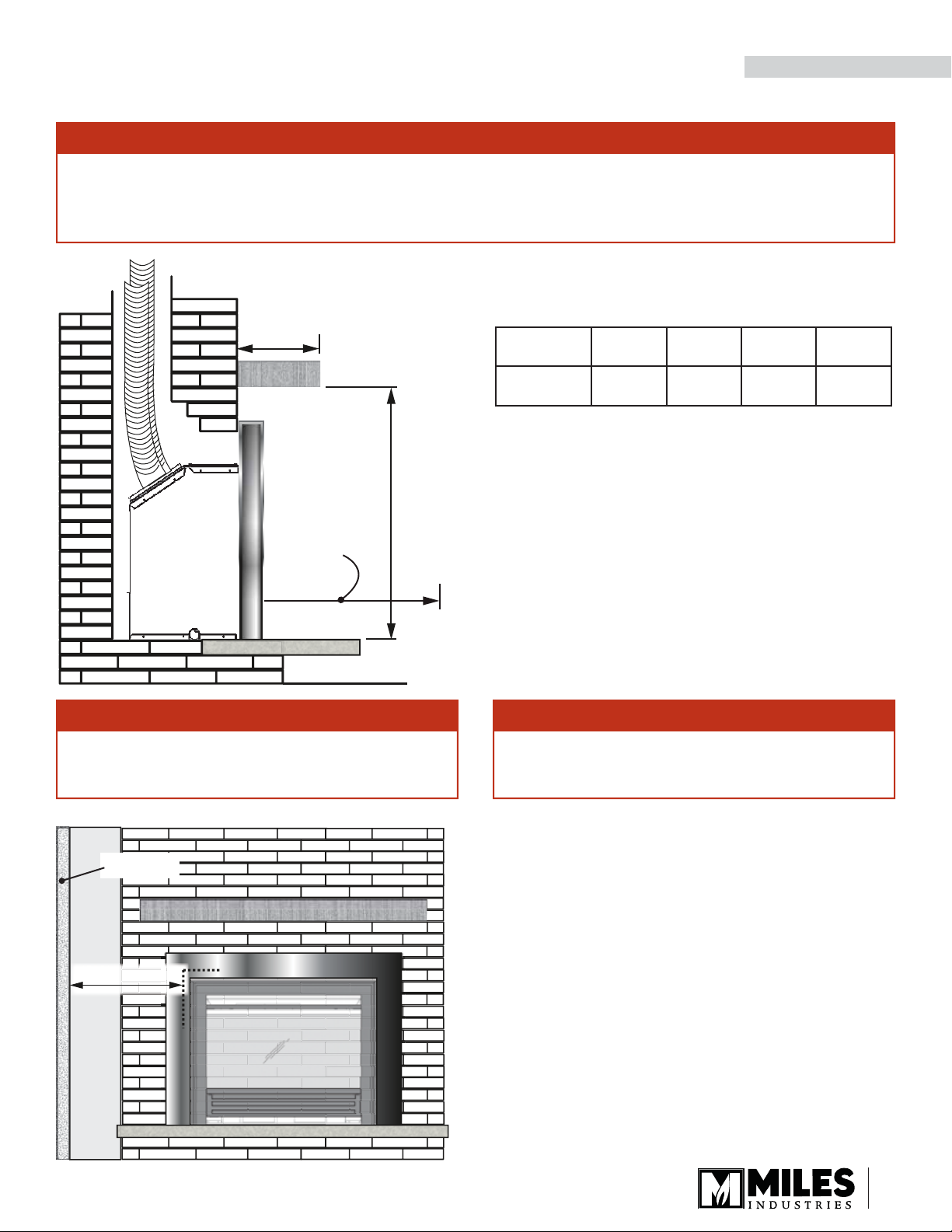
Clearances
INSTALLATION
WARNING
Some materials or items, altough safe, may discolor, warp, crack, peel, and
so on because of the heat produced by the fi replace. Avoid placing candles,
paintings, photos, and other items sensitive to heat around the fi replace.
Combustible Mantel Clearances
A
Do not put
furniture or
objects within
36” (914 mm)
of the front of
appliance
B
WARNING
HOT GLASS!
the glass is highly recommended particularly in
households with children.
The use of a screen in front of
Mantel
Projection A
Mantel
Height B*
*Measure taken from the underside of the mantel to fi nished
hearth or surface that the unit is sitting on.
1”
(25 mm)4”(101 mm)8”(203 mm)
28”
(711 mm)
32”
(813 mm)
35”
(889 mm)
14”
(355 mm)
38”
(965 mm)
Finishing Materials
Combustible materials: Material such as wood,
compressed paper, plant fi bers, plastics or any material
capable of igniting and burning, whether fl ame-proofed
or not, plastered or un-plastered.
Non-combustible materials: Material such as steel,
iron brick, tile, concrete or materials that bear the UL
mark for zero (0) fi re rating.
WARNING
HOT HEARTH!
becomes very hot when the fi replace heats. Do not
use the hearth as a seat or shelf.
The hearth in front of the fi replace
sidewall
9” (229 mm)
Sidewall Clearances
Minimum distance from side of appliance (liner box) to
combustible wall: 9” (229 mm).
9
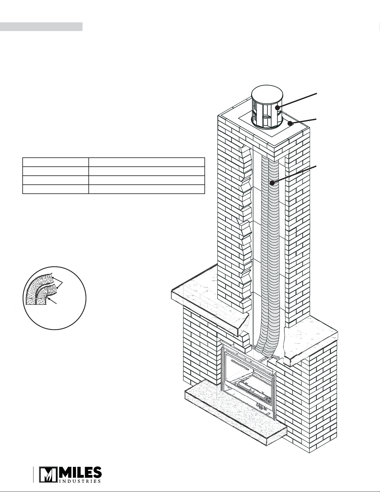
INSTALLATION
Venting
Typical Vent Installation
See list of approved Venting Accessories on page 30 of this manual.
Vent Location
The vent terminal must be located through the
roof. This direct vent appliance is designed to
operate when an undisturbed airfl ow hits the
outside vent terminal from any direction.
Check local codes for allowable vertical vent
termination.
Venting Table
Terminal Cap
Flashing
Maximum vertical height 40 ft (measured to bottom of termination)
Minimum vertical height 10 ft (measured to bottom of termination)
Maximum horizontal run 4 ft (measured center to center of pipe)
Maximum offset angle 45˚ (sweeping bend to allow for obstructions)
Venting Notes
Where possible, avoid joining fl ex pipes. If joints
are required, use a approved connector and seal
joints with RTV high temp sealant.
Four feet horizontal is permissible to allow for
routing around masonry projections. Do not
bend fl ex pipe over a 45 degrees radius.
3” Liners
3” min.
Bend
Radius
2 x 3” fl ex
liners—see
Venting Table
for length
allowed
10

Installation Planning
Installer—READ THIS FIRST
1. YOU NEED TO KNOW FROM THE
HOMEOWNER what accessories (surround,
door, etc.) will be installed with this fi replace;
2. Unpack the appliance.
3. Check that you have everything.
4. Clean cavity, chimney, ash dump, and clean-out.
5. Install venting pipes.
6. Attach conversion plate to existing fi replace.
7. Install and test blower if used.
8. Fit appliance into cavity.
9. Connect and test gas supply.
10. Install ceramic liners, fuel bed and rocks.
11. Refi t window.
12. Put batteries in receiver and remote control
handset.
13. Set-up remote control.
14. Connect electrical wiring blower if used.
15. Verify operation and adjust aeration settings.
16. Install the remote control handset wall holder.
17. Instruct the homeowner on the operation and
maintenance of the fi replace.
18. Install the surround trim and front.
19. Install the fret if required.
INSTALLATION
Tools and supplies required
• Packing knife
• Screwdriver set
• Pliers
• Adjustable Wrench
• Sealant
• Dish soap/water solution
• Gloves
• Eye Protection
• Electric outlet if installing a blower
Existing Fireplace Preparation
A few points must be considered before inserting the
739IR into an existing fi replace cavity. Generally, no
modifi cations are allowed to the existing fi replace that
will compromise the integrity of the existing fi replace.
Components that are bolted or screwed on such as
dampers or baffl es may be removed to accommodate
the installation of the 739IR engine. Cutting away
any sheet metal parts of the existing fi replace
to accommodate the installation of the 739IR is
prohibited. Check with local authorities if in doubt.
Clean Fireplace and Chimney
Have the chimney swept and the fi replace cavity
including ash dumps and clean-outs cleaned before
installing the 739IR heater and vent liners. Any
creosote or soot residue remaining in the fi replace
cavity chimney or clean-out may cause odors or stains
once the 739IR insert is installed. Consult with chimney
sweep for information on how best to clean.
Existing Dampers
Factory-built, zero-clearance fi replaces will require the
damper to be removed in order to install the vent liners.
These dampers are usually bolted into place. Dampers
in masonry fi replaces must be fi xed open and may
remain in place.
Ash Retaining Curbs
Some fi replaces (particularly factory-built) have a
raised curb at the front edge to retain ashes. Check the
dimensions carefully to ensure the 739IR engine will fi t
behind any raised curb (some curbs may be removed
separately from the refractory base).
11
 Loading...