

Valor 737XN, 737XP Installation And Owner's Manual
Vented Gas Fireplace Heaters
Models 737XN & 737XP
with Standard or Cast Front
Installation and Owner’s Manual
Please read this manual before installing and operating this heater
This manual should remain with the homeowner
WARNING: If the information in these
instructions is not followed exactly, a fire
or explosion may result causing property
damage, personal injury or loss of life.
- Do not store or use gasoline or other
flammable vapors and liquids in the vicinity of
this or any other appliance.
-WHAT TO DO IF YOU SMELL GAS
• Do not try to light any appliance.
• Do not touch any electrical switch: do not
use any phone in your building.
• Immediately call your gas supplier from a
neighbor’s phone. Follow the gas supplier’s
instructions.
• If you cannot reach your gas supplier, call
the fire department.
- Installation and service must be performed
by a qualified installer, service agency or the
gas supplier.
This appliance is a domestic room heating
appliance. It must not be used for any other
purpose such as drying clothes etc.
This appliance is suitable for installation in a
bedroom or bed sitting room where not
prohibited by local codes.
600B280/02

CONTENTS
1. SAFETY INFORMATION.......................................................................................................................................................................................... 3
2. OPTIONS ....................................................................................................................................................................................................................... 4
2.1. Additional optional features ............................................................................................................................................................................... 4
3. GENERAL....................................................................................................................................................................................................................... 5
3.1. Approvals & codes ................................................................................................................................................................................................. 5
3.2. Appliance data........................................................................................................................................................................................................ 5
4. LOCATION IN THE ROOM .................................................................................................................................................................................... 6
5. SUPPLY GAS ................................................................................................................................................................................................................. 8
6. PACK CONTENTS...................................................................................................................................................................................................... 9
7. INSTALLATION ........................................................................................................................................................................................................ 10
7.1. Pre-installation preparation ............................................................................................................................................................................. 10
7.2. Install to fireplace................................................................................................................................................................................................ 11
7.3. Installation of gas supply ................................................................................................................................................................................... 11
7.4. Switch to front frame installation.................................................................................................................................................................... 12
7.5. Optional trim installation.................................................................................................................................................................................. 12
7.6. Front frame & switch to appliance .................................................................................................................................................................. 14
7.7. Heat shields installation – Cast front only..................................................................................................................................................... 15
7.8. Ceramic fuel bed installation ........................................................................................................................................................................... 16
7.9. Operation checks................................................................................................................................................................................................. 17
7.10. Fascia installation ................................................................................................................................................................................................ 17
7.11. Venting check ....................................................................................................................................................................................................... 18
7.12. Final check ............................................................................................................................................................................................................ 18
8. OPERATING PROCEDURE .................................................................................................................................................................................. 19
8.1. General operating notes..................................................................................................................................................................................... 19
8.2. Cleaning................................................................................................................................................................................................................. 19
8.3. Checks ................................................................................................................................................................................................................... 21
8.4. Servicing ................................................................................................................................................................................................................ 21
8.5. General servicing ................................................................................................................................................................................................. 21
2
1. SAFETY INFORMATION
WARNING: Do not operate the appliance with the glass
front removed, cracked or broken. Replacement of the
glass should be done by a licensed or qualified service
person.
(The whole window unit may be temporarily removed by
the owner for cleaning the interior of the firebox, etc.)
Only the authorized Valor replacement window unit listed
in the repair parts booklet must be fitted - never use
substitutes.
If the glass is damaged search inside and adjacent to the
appliance for any glass fragments.
Due to high temperatures, the appliance should be located
out of traffic and away from furniture and draperies.
Children and adults should be alerted to the hazards of
high surface temperatures and should stay away to avoid
burns or clothing ignition.
Young children should be carefully supervised when they
are in the same room as the appliance.
Clothing or other flammable material should not be
placed on or near the appliance.
This appliance must be installed and repaired by a
qualified service person. The appliance should be
inspected before use and at least annually by a professional
service person. More frequent cleaning may be required
due to excessive lint from carpeting, bedding material, etc.
It is imperative that control compartments, burners and
circulating air passageways of the appliance are kept
clean.This appliance should be installed and repaired by a
qualified service person.
Keep curtains, clothing, furniture and other flammable
materials a safe distance from all parts of the appliance.
When operating your new furnace for the first time, some vapors may be released which may cause a slight odor and could possibly set off any smoke
detection alarms in the immediate vicinity. These vapors are quite normal on new appliances. They are totally harmless and will disappear after a few
hours use.
Keep the appliance area well clear and free from
combustible materials, gasoline and other flammable
vapors and liquids.
If any changes are made to the room construction in the
vicinity of the appliance after installation (e.g. additional
mantle etc.) make sure that the changes conform to the
installation requirements in this manual.
Never attempt to burn paper or any other material in the
appliance.
Keep the base of the appliance clear to prevent obstruction
of air flow to the appliance.
This appliance must be properly connected to a venting
system. It is equipped with a vent safety shutoff system.
Operating when not connected to a properly installed and
maintained venting system or tampering with the shutoff
system can result in carbon monoxide (CO) poisoning and
possible death.
The venting system should be checked periodically.
Recent trends in home improvement and new tighter
construction techniques have contributed to problems
with venting. If you suspect that your appliance is not
venting properly, do not operate. Seek expert advice.
Do not use this appliance if any part has been under water.
Immediately call a qualified service technician to inspect
the appliance and to replace any part of the control system
and any gas control which has been under water.
NOTE
3

2. OPTIONS
Heater engine unit 737XN is supplied for all natural gas installations.
Heater engine unit 737XP is supplied for all propane installations.
One of the following fascias is supplied with each appliance:
#772SIF Standard fascia
#774CIF Cast fascia
2.1. Additional optional features
#785BAT Brass trim kit for fascia
Facia outer surrounds
#777FSK 4” Black beveled trim – 3 sided
#778FSK 2½” Contoured black trim – 3 sided
#779FSK 2½” Contoured champagne trim – 3 sided
#781FSK 2½” Contoured black trim – 4 sided
#782FSK 2½” Contoured champagne trim – 4 sided
#783FSK 2½” Contoured etched champagne trim – 3 sided
#784FSK 2½” Contoured burgundy trim – 3 sided
#785FSK 2½” Contoured blue trim – 3 sided
#786FSK 2½” Contoured green trim – 3 sided
#787FSK 4” Black beveled trim – 4 sided
#788FSK 2½” Contoured etched champagne trim – 4 sided
#789FSK 2½” Contoured burgundy trim – 4 sided
#790FSK 2½” Contoured blue trim – 4 sided
#791FSK 2½” Contoured green trim – 4 sided
Circulating fan kit
#796CFK Operated by a 3 position switch, the fan is designed to boost the natural convection process through the heater. This may
be a desirable feature dependent on the fireplace location and room layout. The circulating fan may be installed during initial appliance
installation or as a retrofit at a later date. Full installation and operating instructions are included with the kit.
Zero clearance kit
#770ZCK Allows the furnace to be installed into an enclosure constructed of combustible material. The kit must be used in this form of
enclosure. Enclosure framing dimensions suitable for the kit are shown in section 4 of this manual. This zero clearance kit has been
designed to act as a “rough in” box with the appliance model 737X purchased and/or fitted after the walls of the enclosure and the
hearth have been fitted. Full installation instructions are included with the kit.
Clearance reduction baffle
#771CRB Allows combustible mantles to be fitted closer to the fireplace. Full installation instructions are included with the kit.
4
3. GENERAL
3.1. Approvals & codes
This appliance is certified by International Approval Services for use in Canada and the USA. The appliance is for installation
connected to an approved 3” dia. liner or B-vent.
The appliance complies with CGA P.4.1, Testing method for measuring annual fireplace efficiencies.
The installation must conform with local codes or, in the absence of local codes with the National Fuel Gas Code, ANSI Z223.1or the
Canadian installation code CAN/CGA-149. Only qualified licensed or trained personnel should install the appliance.
The appliance, when installed, must be electrically grounded in accordance with local codes or, in the absence of local codes, with the
National Electrical Code, ANSI/NFPA 70 or the Canadian Electrical Code, CSA C22.1
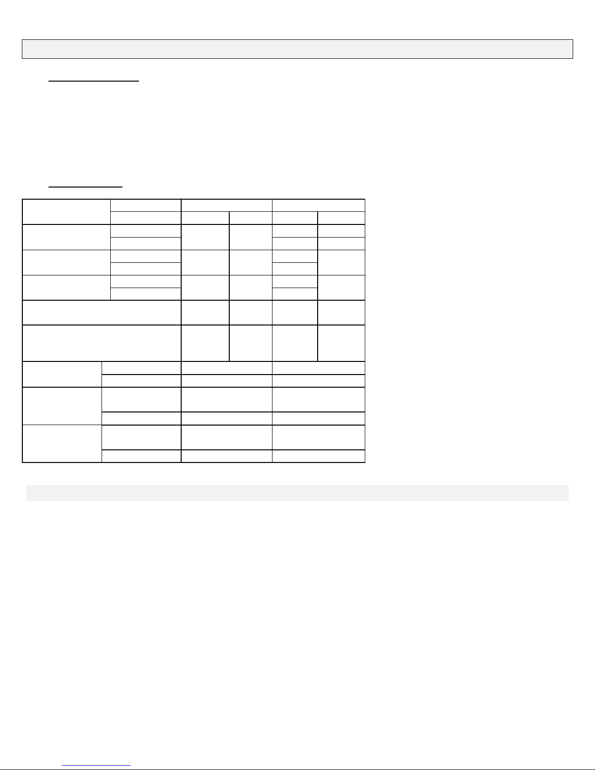
3.2. Appliance data
737XN 737XP
Altitude (ft) Max. Min. Max. Min.
Input (Btu/h)
Output-Fan Off
Output-Fan On
2000-4500 18,910*
Supply-Upstream of Regulator
(in w.c.)
Manifold-Tapping on
Thermostat (Appliance full on)
(in w.c.)
Pilot orifice Type
No. of holes
Front burner
orifice
No. of holes
Rear burner
orifice
No. of holes
* After adjustment
0-2000 28,900 9,860 28,400 17,000
2000-4500 25,045* 15,180*
0-2000 20,519 20,166
2000-4500 17,782*
0-2000 21,390 21,443
10.5 5.0 14.0 11.0
4.0 3.6 9.5 9.1
Cat 960-45 Cat 960-15
1 1
Type
Cat 82-360 Cat 92-130
7 1
Type
Cat 82-440 Cat 960-190
7 1
5

4. LOCATION IN THE ROOM
The appliance can be installed in the following constructions:
2.1 Solid fuel (Non-combustible) fireplaces
As supplied, this appliance can be installed as an inset in an existing solid fuel type fireplace with a chimney and 3" dia liner (see
fig.1a).
The fireplace must be built in accordance with the national, state provincial or territorial building code recognized by the
authority having jurisdiction, or in the absence of such a code, in accordance with the National Building Code of Canada or the
National Fire Protection Association code in the USA The size of the fireplace recess must be sufficient to accommodate the
appliance case as shown in fig.1a.
The chimney must be swept and both chimney and fireplace checked for soundness before installation of the appliance. The liner
must be a type approved by the enforcing authority and installed in accordance with the manufacturer's instructions.
The appliance must be installed on a non-combustible floor. The floor must be sufficiently flat and level to support the appliance
satisfactorily. Some fireplace constructions have a well in the floor at the back that may need to be filled in. In the USA it is
mandatory that a hard surfaced non-combustible hearth area must be maintained at least 16" in front of the fireplace. This may be
finished in brick, ceramic tile, marble
unit.
In Canada, though not mandatory, we recommend that carpet, soft vinyl or other combustible floor coverings are kept at least 16”
from the front of the furnace since these types of materials may be affected by the high radiant heat output from this appliance.
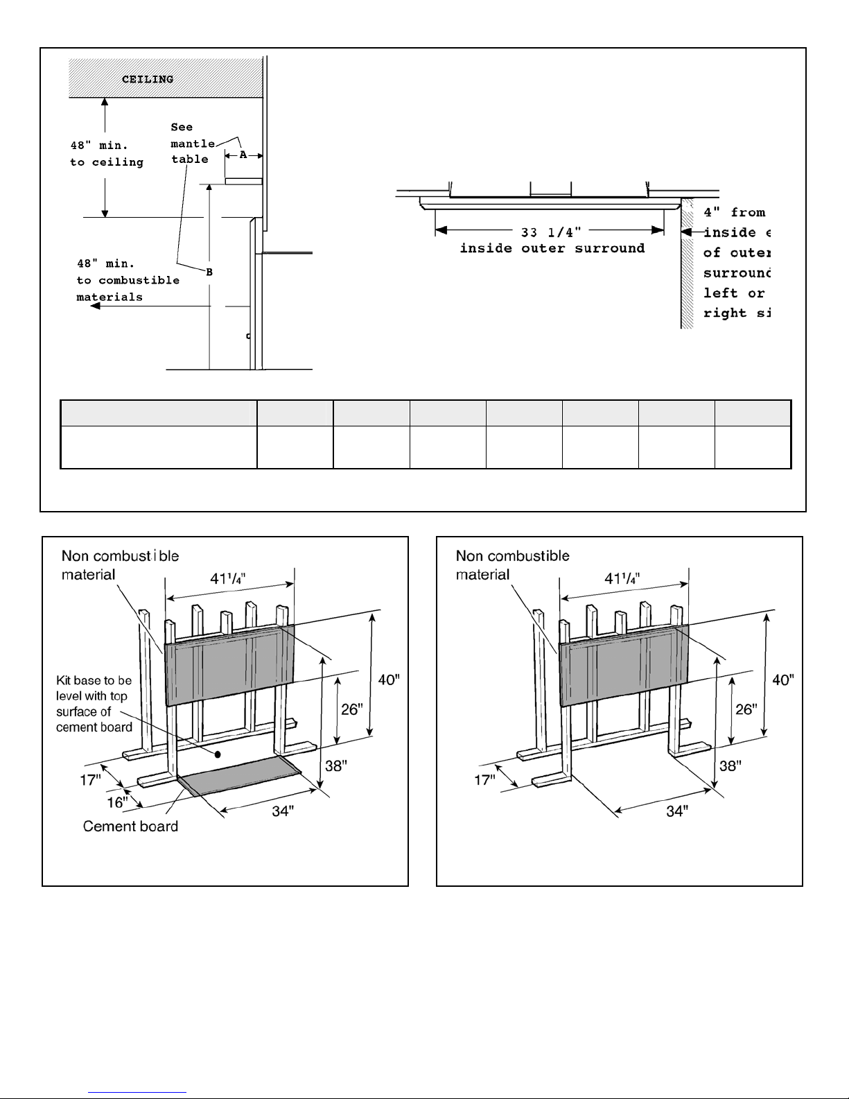
The minimum clearances from any combustible constructions at the front of the appliance are shown in fig.1b. These front
clearances apply for all installations.
2.2 Enclosures constructed with combustible materials
#770ZCK Zero clearance kit must be installed where the furnace is intended to be in an enclosure made with wood studding or
other combustible materials.
The enclosure framing requirements are shown in figures 1c through 1f.
Note that in Canada, though not mandatory, we recommend that carpet, soft vinyl or other combustible floor coverings are kept
at least 16” from the front of the furnace since these types of materials may be affected by the high radiant heat output from this
appliance.
, etc. Raising the hearth slightly will help to minimize dust and lint accumulation under the
Fig. 1a Solid fuel fireplace dimensions
6
w
w
MANTLE DEPTH “A” 1” 2” 3” 4” 5” 6” 7”
CLEARANCE FROM BASE OF
HEATER “B”
Fig. 1b Clearances to combustible materials in front of enclosure opening - All installations
Fig 1c Combustible material enclosure - For installations in USA
ith protected combustible floor
37 7/8” 39 7/8” 40 7/8” 42 7/8” 44 7/8” 46 7/8” 48 7/8”
Fig 1d Combustible material enclosure - For installations in Canada
ith unprotected combustible floor
7
 Loading...