

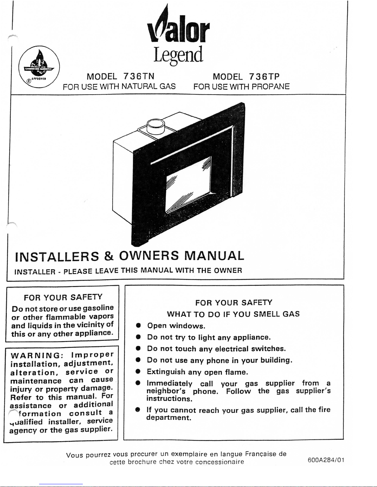
Valor 736TN, 736TP Installer's & Owner's Manual
CAUTION
Due to high temperatures, the appliance should
Keep area in front of bottom grill clear to pre-
,.
be located out of traffic and away from furniture
vent obstruction of air flow to appliance for
and draperies. combustion.
Children and adults should be alerted to the
hazards of high surface temperatures and should
stay away to avoid burns or clothing ignition.
Young children should be carefully supervised
when they are in the same room as the appliance.
Clothing or other flammable material should
not be placed on or near the appliance.
The glass and front frame must be put back in
place prior to operating the appliance if they
have been removed for servicing or cleaning.
This appliance should be installed and repaired
by a qualified service person.
The appliance should be inspected before use
,-.and at least annually by a professional service
Serson. More frequent cleaning may be required due to excessive lint from carpeting,
bedding material, etc.
It
is imperative that con-
trol compartments,
burners and circulating air
passageways of the appliance be kept
clean.
Keep curtains, clothing, furniture and other
flammable materials at least
36ins. (900mm)
from the front and top of the appliance.
Keep the appliance area well clear and free from
combustible materials, gasoline and
otherflam-
mable vapors and liquids.
Neverattempt to burn paper or any other material
in the appliance.
This appliance requires a source of fresh air in
order to vent properly. The venting system
should be checked periodically.
Recent trends in home improvement and new
tighter construction techniques have contributed to problems with venting.
If
you suspect
that your appliance is not venting properly, do
not operate and seek expert advice.
Do not use this appliance if any part has been
under water. linmediately call a qualified service technician to inspect the appliance and to
replace any part of the control system and any
gas control which has been under water.
NOTE
-
If
any changes are made to the room construc-
tion in the vicinity of the appliance
after installation
(e.g. additional mantle etc.),
make sure that such chahges conform to the
installation requirements in this manual.
When equipped with the optional circulating fan
kit (Part
#710CFK) or power vent kit (Part
#720PVC), the appliance must be installed and
electrically grounded in accordance with local
codes or, in the absence of local codes, with the
latest edition of the Canadian Electrical
Code, CSA
C22-1.
This heater must be properly connected to a
venting system. Operation of this
heater when not connected to a properly
installed and maintained venting system can
result in carbon monoxide
(CO)
poisoning
and possible death.
On first lighting your new appliance there may be a slight odor and the appearance of a slight amount
of
vapor.
This
is normal with new appliances . It is not harmful and Will disappear within a short time.
1.
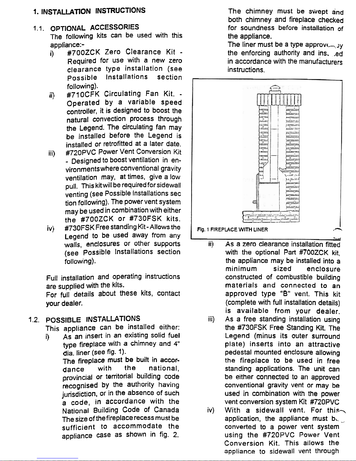
INSTALLATION INSTRUCTlONS
The chimney must be swept and
both chimney and fireplace checked
1.1.
OPTIONAL
ACCESSORlES for soundness before installation of
The following kits can be used with this
the appliance.
appliance:-
The liner must be a type approvc-JY
i)
#700ZCK Zero Clearance Kit
-
the enforcing authority and ins.
,ed
Required for use with a new zero
in accordance with the manufacturers
clearance type installation (see instructions.
possible lnstallations section
following).
ii)
#710CFK Circulating Fan Kit.
-
Operated by a variable speed
controller, it is designed to boost the
natural convection process through
the Legend. The circulating fan may
be installed before the Legend is
installed or retrofitted at a later date.
iii)
#720pVC Power Vent Conversion Kit
-
Designed to boost ventilation in environments where conventional gravity
ventilation may,
at times, give a low
pull. This kit will be required for sidewall
venting (see Possible lnstallations sec
tion following). The power vent system
may be used in combination with either
the
#700ZCK or #730FSK kits.
iv)
#730~SK Free standing Kit - Allows the
Legend to be used away from any
Fig.
1
FIREPLACE
LINER
n
--
-,
walls, enclosures or other supports
ii)
As a zero clearance installation fitted
(see Possible Installations section
with the optional Part #700ZCK kit,
following).
the appliance may be installed into a
minimum sized enclosure
FUI~
installation and operating instructions
constructed of combustible building
are supplied with the kits.
materials and connected to an
For full details about these kits, contact
approved type
"8"
vent. This kit
your dealer.
(complete with full installation details)
is available from your dealer.
1.2.
POSSIBLE INSTALLATIONS iii) As a free standing installation using
This appliance can be installed either:
the #730FSK Free Standing Kit. The
i)
AS
an insert in an existing solid fuel
Legend (minus its outer surround
type fireplace with a chimney and
4"
plate) inserts into an attractive
dia. liner (see
fig.
1).
pedestal mounted enclosure allowing
The fireplace must be built in accor-
the fireplace to be used in free
dance with the national, standing applications. The unit can
or territorial building code
be either connected to an approved
recognised by the authority having
conventional gravity vent or may be
jurisdiction, or in the absence of such
used in combination with the power
a code,
in
accordance with the
vent conversion system Kit #720PVC
National Building Code of Canada iv) With a sidewall vent. For thi.s-,
The size of the fireplace recess must be
application, the appliance must
bc
_
sufficient to accommodate the converted to a power vent system
appliance case as shown in fig.
2.
using the #720PVC Power Vent
Conversion Kit. This allows the
appliance to sidewall
vent
through
.
,
any approved 4" dia. vent to a
remote
fanlhood up to 75 feet from
the appliance,
All installations must conform with local
p.
codes or, in the absence of local codes
with the current
CANICGA1-6149
Installation Code. Only qualified (licensed or
trained) personnel should install the
appliance.
1.3.
SUPPLY
GAS
Model 736TN is for use only with Natural
Gas. The natural gas supply pressure at
the appliance inlet connection should be
not less than
5"w.c. and not more than
10.5"w.c.
Model 736TP is for use only with Propane
Gas. The propane supply pressure at the
appliance inlet connection should be not
less than
1l"w.c. and not more than
1
4"w.c.
The supply connection to both appliances
is
318" NPT.
1.3.1.
Gas
Feed Line
The supply gas feed line should enter
the appliance through one of the
openings in the appliance case.
Openings are provided at the back and
right side. (see fig. 4). See section 4
for g'as supply connection details.
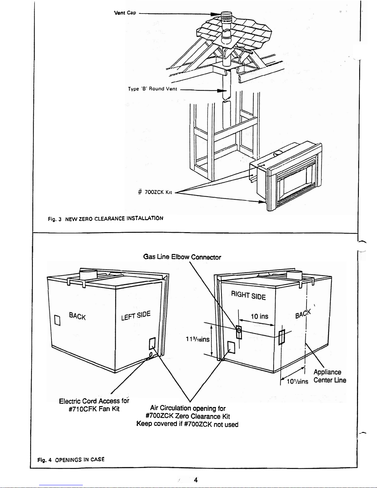
Top
of
gr~lle
ouller
4"
MIN
Side
Clearance
Lett
and
right
s~des
Vent
Fig.
3
NEW ZERO CLEARANCE INSTALLATION
-
Gas tine Elbow Connector
Fig. 4 OPENINGS IN CASE
Electric Cord Access
for
#71
OCFK Fan Kit
Air Circulation opening for
#7OOZCK Zero Clearance Kit
Keep covered if
#700ZCK not used
-
.
1.4.
CLEARANCES TO
COMBUSTlBLE
CONSTRUCTIONS
The minimum clearances from any
r--
combustible constructions at the front of
the appliance are shown in fig.
2.
These
front clearances apply for all installations
-
whether in solid fuel fireplace, new zero
clearance construction or free standing.
If, it is intended to fit the appliance in a
combustible recess, the Zero Clearance
Kit
#700ZCK (available from your dealer)
must be used as shown in fig.3.
1.5.
FLOOR
The floor in the fireplace recess must be
sufficiently flat and level to support the
appliance satisfactorily. Some fireplace
constructions have
a
well in the floor at
the back which may need to be filled in.
Do not place the appliance on carpeting,
vinyl or other soft-surfaced floor coverings.
Install only on hard surfaced materials.
We recommen'd that a hard surfaced
hearth area be maintained at least
12"
in
-3
front of the fireplace for both aesthetic and
maintenance purposes. This may be
finished in brick, ceramic tile, marble etc.
Raising the hearth slightly will help to
minimise dust and lint accumulation
under
the unit.
If the appliance is installed directly on any
combustible material other than wood
flooring, the appliance shall be installed on
a
metal or wood panel extending the full
lance.
width and depth of the app"
1.6.
APPLIANCE PACK CONTENTS
The pack contains:-
1
Appliance fitted with front unit.
3 Ceramic Logs.
1
Pair ceramic firebox side walls.
1
Ceramic firebox back wall.
~
2
Outer surround side channels.
1
Outer surround top channel.
+.
1
Bag of screws, nuts and washers
for outer surround fixing.
1 Supply line elbow connector.
Take care when removing the contents
from the packaging to prevent damage.
Check that all the contents are in the pack
and are undamaged.
e
2
INSTALLING IN EXISTING FlREPLACE
2.1
PRE-INSTALLATION PREPARATION
2.1.1. Closing Large Fireplace Openings
This appliance
is
suitable for fire-
place openings from 21" to
25 1/4"
high and
31
114"
to 39" wide. For
infilling larger fireplace openings
.the
fireplace opening may be reduced
or the outer surround plate extended
provided non-combustible materials
are used.
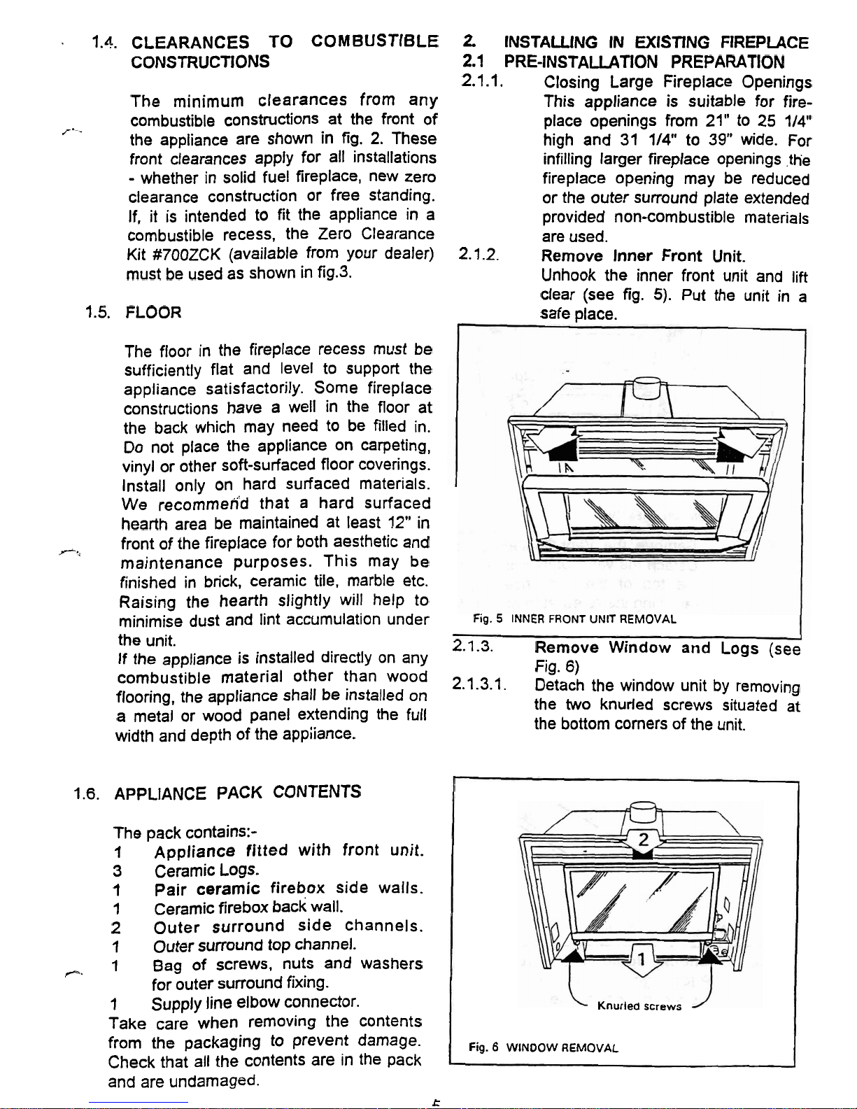
2.1.2. Remove Inner Front Unit.
Unhook the
inner front unit and lift
clear (see
fig.
5).
Put
the unit in a
safe place.
Fig.
5
INNER
FRONT
UNIT
REMOVAL
2.1.3.
Remove Window and Logs (see
Fig.
6)
2.1.3.1.
Detach the window unit by removing
the two knurled screws situated at
the bottom comers of the unit.
Knurled
screws
Fig.
6
WINDOW
REMOVAL
 Loading...