

Valor 716EHC, 716EHV, 717BPB, 719BP, 716EHOZ Installation Instructions Manual
...
LEGEND G3.5
716 Edgemont Hammered Trim Kit
Use with Valor 700 Models only
Installation Instructions
for 716EHC, EHV, EHOZ, 717BPB and 719BPB kits
!
A barrier designed to reduce the risk of burns from the hot
viewing glass is provided with this appliance and shall be
installed for the protection of children and other at-risk
individuals.
The 716 Edgemont Hammerered Trim Kit is intended
to be used with the Backing Plate 717BPB or 719BPB
installed on the Valor heater model 700.
The 716 fi tted with the 717 backing plate can also be
installed with an additional backing plate 710BPB or
714BPB as well as a riser trim 725RT or 793RT to
cover larger cavity opening.
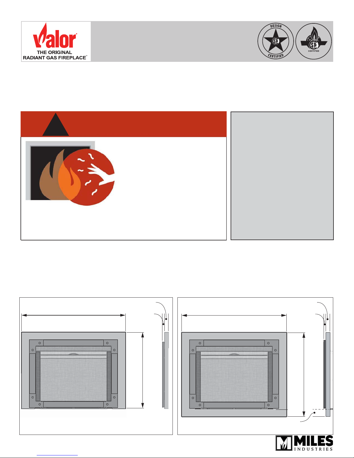
36-1/4” (922 mm)
DANGER
HOT GLASS WILL
CAUSE BURNS.
DO NOT TOUCH GLASS
UNTIL COOLED.
NEVER ALLOW CHILDREN
TO TOUCH GLASS.
Please note the appliance will have to be raised by
2-5/8” when using the 719BPB 4-Sided Backing Plate
!
as the plate extends below the bottom of appliance.
Mounting of the 716 does not affect clearances or other
specifi cations listed in the heater installation manuals—
see installation manual supplied with the heater for
more information.
1-1/2”
(38 mm)
1/2”
(13 mm)
Leave this manual
with the appliance.
Retain this manual
for future reference.
36-5/16” (922 mm)
INSTALLER
CONSUMER
1-1/2”
(38 mm)
1/2”
(13 mm)
716EH with 717BPB—
3-sided Backing Plate
4005661-02
© Copyright Miles Industries Ltd., 2016
26-5/8” (677 mm)
716EH with 719BPB—
4-sided Backing Plate
2-5/8” (67 mm)
between bottom of trim
and bottom of appliance
!
29-1/4” (742 mm)
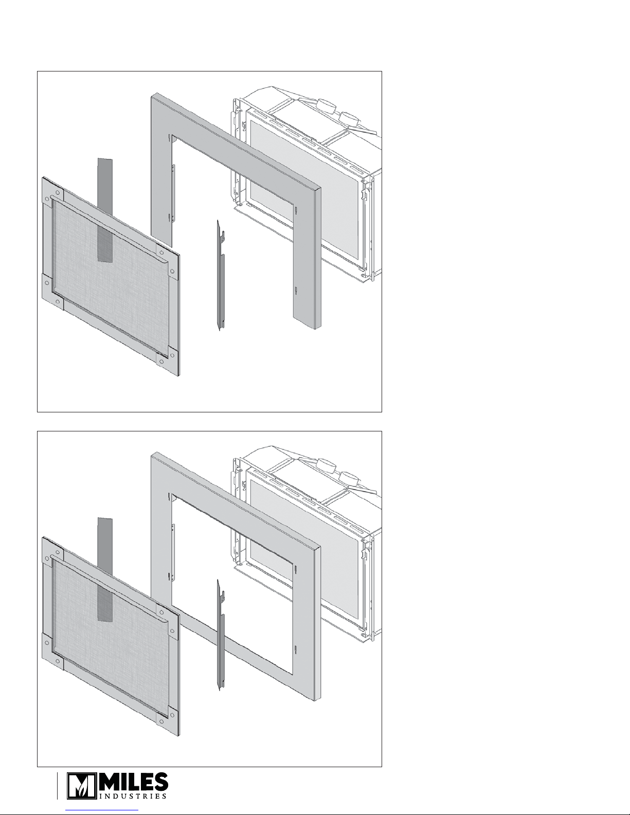
Overview
717BPB Backing Plate
(sold separately)
LH side door
700 engine
RH side door
Edgemont hammered
barrier screen door
716EH Edgemont Hammer with 717BPB 3-Sided Backing Plate
700 engine
719BPB Backing Plate
(sold separately)
LH side door
RH side door
Edgemont hammered
barrier screen door
716EH Edgemont Hammer with 719BPB 4-Sided Backing Plate
2
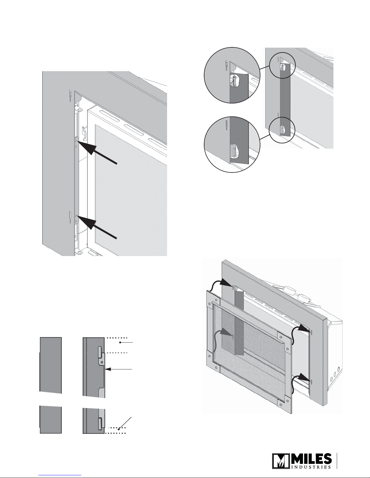
Installation
TOP of door:
this space is
wider
TOP of door:
notch in the
rear ange
Left door panel
BOTTOM of door:
this space is
narrower
Rear viewFront view
1. Fit the 717BPB or 719BPB backing plate to the
shrouds (side brackets) supplied with the fi replace
with two screws per side.
Note: Use the upper hole in the backing plate to fi x
it to the shrouds.
4. Insert the top pin of the left door panel in the hole
at the top of the left shroud already installed on the
appliance.
5. Lift the panel as far as possible and insert the
bottom pin in the hole at the bottom of the shroud.
The panel should rotate freely.
6. Install the right door panel the same way.
7. Hook the barrier screen door to the backing plate
as indicated.
Note: The barrier screen door, when hooked to
the backing plate, protrudes slightly in front of
the plate.
2. Identify the left and right door panels using the
image below.
3. Identify the top and bottom of the left panel. The
notch in the rear fl ange of the panel is at the top.
The space between the rear fl ange and the edge
of the panel is wider at the top than at the bottom
of the panel as shown below.
3
 Loading...