

Valor 639 Installer's Manual
MODEL
639
Open Decorative
Gas Fire
(G.C No. 32-032-47)
INSTALLER’S GUIDE
THIS APPLIANCE IS FOR USE WITH NATURAL GAS (G20)
WHEN CONVERTED USING CONVERSION KIT NO. 0591301 THIS
APPLIANCE IS FOR USE WITH PROPANE GAS (G31)
THIS APPLIANCE IS FOR USE IN THE UNITED KINGDOM (GB) AND
THE REPUBLIC OF IRELAND (IE) ONLY.
We trust that these instructions give sufficient details to enable this appliance to
be installed and maintained satisfactorily. However, if further information is
required, our Valor Technical Helpline will be pleased to help.
Please telephone 08706 061 065
INSTALLER: Please leave this guide with the owner
© Valor Heating
3002369/03
INSTALLER’S GUIDE
Page 2
Safety First.
Valor fires are CE Approved and designed to meet the appropriate British
Standards and Safety Marks.
Quality and Excellence.
At the heart of every Valor fire.
All Valor fires are manufactured to the highest standards of quality and excellence
and are manufactured under a BS EN ISO 9001 quality system accepted by the
British Standards Institute.
The Highest Standards
Valor is a member of the Society of British Gas Industries which works to ensure
high standards of safety, quality and performance.
Careful Installation
Valor is a CORGI registered company. All our gas fires must be
installed by a competent CORGI Registered Installer in accordance
with our Installer Guide and should not be fitted directly on to a
carpet or floor of combustible material.
Valor Heating, Erdington, Birmingham B24 9QP
www.valor.co.uk
Because our policy is one of constant development and improvement, details may vary slightly from
those given in this publication

INSTALLER’S GUIDE
Page 3
CONTENTS
1. SAFETY ..........................................................................................................4
2. LIST OF ACCESSORIES .............................................................................4
3. APPLIANCE DATA ......................................................................................5
4. GENERAL INSTALLATION REQUIREMENTS ....................................6
5. UNPACKING ...............................................................................................12
For models supplied with a firefront ..............................................................12
For models supplied with a coal effect fuel bed ............................................12
For models supplied with a Pebble effect fuel bed ........................................12
6. INSTALLATION OF APPLIANCE ..........................................................13
7. BURNER AND SUPPLY PIPE INSTALLATION................................... 16
Lighting the fire.............................................................................................. 16
8. INSTALLING THE FUEL BED COMPONENTS ..................................18
9. FITTING THE FIREFRONT.....................................................................29
10. FULL OPERATING CHECKS .................................................................. 31
Flame Supervision & Spillage Monitoring System .......................................32
Final commissioning ......................................................................................32
11. SERVICING & PARTS REPLACEMENT ..............................................33
Checking the aeration setting of the burner....................................................34
12. SHORT LIST OF SPARES.........................................................................37

INSTALLER’S GUIDE
Page 4
1. SAFETY
Installer
• Before continuing any further with the installation of this appliance please read
the following guide to manual handling
• The lifting weight of this appliance is 9 kg. One person should be sufficient to
lift the fire. If for any reason this weight is considered too heavy then obtain
assistance.
• When lifting always keep your back straight. Bend your legs and not your
back.
• Avoid twisting at the waist. It is better to reposition your feet.
• Avoid upper body/top heavy bending. Do not lean forward or sideways whilst
handling the fire.
• Always grip with the palm of the hand. Do not use the tips of fingers for
support.
• Always keep the fire as close to the body as possible. This will minimise the
cantilever action.
• Use gloves to provide additional grip.
• Always use assistance if required.
2. LIST OF ACCESSORIES
The following accessories are available: -
Description Part Number
• All Models
LPG Conversion kit 0591301
• ‘Quattro’, ‘Majestic’ and Models not supplied with a firefront
Replacement chairbrick 0552311
Replacement chairbrick Brass effect Trim 0552321
Replacement chairbrick Chrome effect Trim 0552331
Replacement chairbrick Black Trim 0552341
• ‘Azure’ Model
Replacement chairbrick 0552301
INSTALLER’S GUIDE
Page 5
3. APPLIANCE DATA
This product uses fuel effect pieces and gaskets containing Refractory
Ceramic Fibres (RCF), which are man-made vitreous silicate fibres.
Excessive exposure to these materials may cause irritation to eyes, skin and
respiratory tract. Consequently, it is important to take care when handling
these articles to ensure that the release of dust is kept to a minimum. To
ensure that the release of fibres from these RCF articles is kept to a
minimum, during installation and servicing we recommend that you use a
HEPA filtered vacuum to remove any dust and soot accumulated in and
around the fire before and after working on the fire. When replacing these
articles we recommend that the replaced items are not broken up, but are
sealed within a heavy duty polythene bag, clearly labelled as RCF waste. This
is not classified as “hazardous waste” and may be disposed of at a tipping site
licensed for the disposal of industrial waste. Protective clothing is not
required when handling these articles, but we recommend you follow the
normal hygiene rules of not smoking, eating or drinking in the work area and
always wash your hands before eating or drinking.
This appliance does not contain any component manufactured from asbestos or
asbestos related products.
The appliance data label is located below the burner and is visible when the fire
front cover is removed.
639 (Natural Gas) 639 (Propane)*
Gas Natural (G20) Propane (G31)
Inlet Pressure 20mbar (8in. w.g.) 37mbar (14.8in. w.g.)
Input - Max. ( Gross) 6.85kW (23,380Btu/h) 6.7kW (22,860Btu/h)
Input - Min. ( Gross ) 2.3kW (7,850Btu/h) 4.0kW (13,650Btu/h)
Burner injector Bray Cat.18U Size 420 Stereomatic. Size 170
Burner Test Pressure-
Cold
17.9mbar + 0.75mbar
(7.2in w.g. + 0.3in w.g.)
35.85 mbar + 0.75mbar
(14.4in w.g. + 0.3in w.g.)
Inlet Pipe Connection 8mm 8mm
Pilot & Atmosphere
Sensing Device
OP NG9030 OP LPG9222
Ignition Integral Piezo Spark Integral Piezo Spark
Aeration Non-Adjustable Non-Adjustable
*When converted using kit 0591301

INSTALLER’S GUIDE
Page 6
4. GENERAL INSTALLATION REQUIREMENTS
4.1 The installation must be in accordance with these instructions.
For the user’s protection, in the United Kingdom it is the law that all gas appliances
are installed by competent persons in accordance with the current edition of the
Gas Safety (Installation and Use) Regulations. Failure to install the appliance
correctly could lead to prosecution. The Council for the Registration of Gas
Installers (CORGI) requires its members to work to recognised standards.
In the United Kingdom the installation must also be in accordance with:
a) All the relevant parts of local regulations.
b) All relevant codes of practice.
c) The relevant parts of the current editions of the following British Standards:-
BS 1251
BS 4543 Part 2
BS 5440 Part 1
BS 5440 Part 2
BS 5871 Part 3
BS 6461 Part 1
BS 6891
BS 8303
d) In England and Wales, the current edition of the Building Regulations issued
by the Department of the Environment and the Welsh Office. In Scotland the
current edition of the Building Standards (Scotland) Regulations issued by the
Scottish Executive. In Northern Ireland, the current edition of the Building
Regulations (Northern Ireland) issued by the Department of the Environment for
Northern Ireland. In the Republic of Ireland the installation must also conform
with the relevant parts of:
The current editions of:-
3 IS 813
3 ICP3
3 IS327
1. All relevant national and local rules in force.
4.2 As supplied the appliance can be installed in the following situations: -
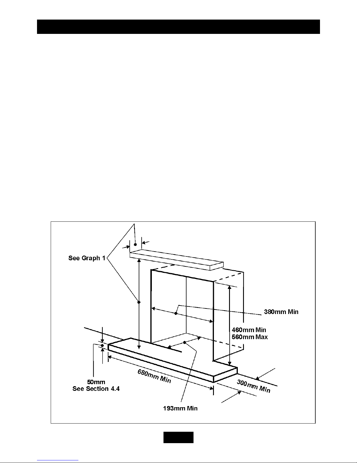
• To a fireplace complete with surround and hearth as shown in figure 1 and
complying with BS1251. The required fireplace, hearth, and clearance
dimensions are shown in figure 1.
• Into a fireplace that has a fireback of nominal size 400mm and conforming to
BS1251.
INSTALLER’S GUIDE
Page 7
Into a Replacement Chair Brick as below: -
• ‘Quattro’, ‘Majestic’ and Models not supplied with a firefront
Into a Valor Replacement Chairbrick. Part number 0552311
• ‘Azure’ Model
Into a B&Q Replacement Chairbrick. Part number 0552301
Suitable flues and minimum flue sizes are as follows: -
2. 225mm x 225mm conventional brick flue.
3. 175mm diameter lined brick or stone flue.
4. 200mm diameter factory made insulated flue manufactured to BS4543.
5. 175mm diameter flue pipe. See BS6461 Part 1 for suitable materials.
The minimum effective height of the flue must be 3m.
The flue must not be used for any other appliance or application.
Any chimney damper or restrictor should be removed. If removal is not possible,
they must be secured in the open position.
If the appliance is intended to be installed to a chimney that was previously used for
Figure 1. Hearth and Fireplace Opening

INSTALLER’S GUIDE
Page 8
solid fuel, the flue must be swept clean prior to installation. All flues should be
inspected for soundness and freedom from blockages.
4.3 If the fireplace opening is an underfloor draught type, it must be sealed to
stop any draughts.
4.4 The appliance must be mounted behind a non-combustible hearth (N.B.
conglomerate marble hearths are considered as non-combustible). The appliance can
be fitted to a minimum class “O” – 100°C surround. The hearth material must be at
least 12mm thick. The periphery of the hearth (or fender) should be at least 50mm
above floor level to discourage the placing of carpets or rugs over it (See figure 1).
The surface of the hearth must be sufficiently flat to enable the bottom of the front
surround and the bottom front cover to be aligned horizontally. Any excessive
unevenness (uneven tiles, Cotswold stone, etc.) should be rectified.
4.4.1. ‘Hole-in-the-wall’ Installations
• It is recommended that a hearth should be installed as in figure 1.
• If a reduced depth Hearth is fitted, the fire must be installed so that the
distance from the base of the fireplace opening in the wall to the finished
floor level is 85mm minimum. It is recommended that the reduced hearth
has a depth from the fixing plane of the fire of 100mm minimum. This is
necessary to support the lower front casting.
4.5 If the Fireplace opening is greater than the acceptable dimensions given in this
guide, do not use the back of a fire surround or marble to reduce the opening. This
may cause cracking of the surround back or marble
4.6 The appliance must not stand on combustible materials or carpets.
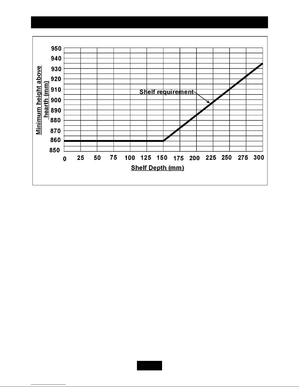
4.7 The minimum height from the top of the hearth to the underside of any shelf
made from wood or other combustible materials is as follows: -
• For a shelf up to 150mm deep
Minimum height = 860mm.
• For a shelf deeper than 150mm
860mm + 12.5mm for every 25mm depth over 150mm
(See Graph 1).
INSTALLER’S GUIDE
Page 9
4.8 Note that soft wall coverings (e.g. embossed vinyl, etc.) are easily affected by
heat. They may scorch or become discoloured when close to a heating appliance.
Please bear this in mind when installing.
4.9 This appliance must not be installed in any room that contains a bath or shower
or where steam is regularly present.
4.10 An extractor fan may only be used in the same room as this appliance, or in
any area from which ventilation for the appliance is taken, if it does not affect the
safe performance of the appliance. Note the spillage test requirements detailed
further on in this manual. If the fan is likely to affect the appliance, the appliance
must not be installed unless the fan is permanently disconnected.
In the United Kingdom (GB) no special ventilation bricks or vents are normally
required in the room for this appliance.
In the Republic of Ireland (IE) permanent ventilation must comply with the rules in
force.
4.11 Propane gas appliances must not be installed in a room that is built entirely
below ground level (see BS 5871 Part 3).
Graph 1. Combustible shelf clearances.
INSTALLER’S GUIDE
Page 10
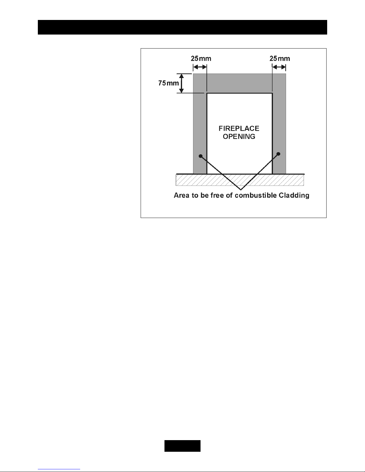
4.12 If the appliance is to
be fitted against a wall with
combustible cladding, the
cladding must be removed
from the area shown in
figure 2
4.13 Combustible side
projections up to 75mm
forward of the fixing plane
of the fire are to be a
minimum of 125mm from
the fireplace opening (See
figure 3)
4.14.1 Combustible side
projections greater than
75mm forward of the fixing
plane of the fire are to be a minimum of 178mm from the fireplace opening (See
figure 3).
4.14.2 Non-combustible side projections to be 75mm from the fireplace
opening (See figure 3)
Figure 2. Removal of Combustible cladding

INSTALLER’S GUIDE
Page 11
Firefront Dimension ‘X’ (mm) Dimension ‘Y’ (mm)
Azure 400 65
Quattro 390 65
Majestic 400 50
Figure 3. Appliance dimensions

INSTALLER’S GUIDE
Page 12
5. UNPACKING
Contents:
1 Burner assembly
1 Nut & olive for 8mm inlet pipe
2 Screws
2 Plastic screw plugs
1 Fuel bed matrix support plate
2 Self tapping screws
1 Combined instruction guide
For models supplied with a firefront
1 Firefront and Cover
For models supplied with a coal effect fuel bed
2 Front coals (1 x right hand 1 x left hand )
1 Coal matrix
1 Pack of loose coals containing 12 coals
For models supplied with a Pebble effect fuel bed
2 Front Pebbles (1 x right hand 1 x left hand )
1 Pebble matrix
1 Pack of loose pebbles containing 16 pebbles
Carefully remove the contents. Take special care in handling the ceramic
components and the coals / Pebbles. Check that all the listed parts are present and
in good condition.
 Loading...