

Valor 546LFB ZC Portrait Ledgeview Front Installation And Owner's Manual
PORTRAIT
Ledgeview Fronts 546LFB ZC
Approved for use with Valor heater models 530 only in ZC applications;
NOT compatible with 530INI/IPI insert engines
Installation and Owner’s Manual
INSTALLER
!
A barrier designed to reduce the risk of burns from the hot
viewing glass is provided with this appliance and shall be
installed for the protection of children and other at-risk
individuals.
DANGER
HOT GLASS WILL
CAUSE BURNS.
DO NOT TOUCH GLASS
UNTIL COOLED.
NEVER ALLOW CHILDREN
TO TOUCH GLASS.
Notes: This kit must be installed
or serviced by a qualifi ed installer,
service agency or gas supplier.
These instructions are to be used
in conjunction with the main
installation instructions for the
above listed heater models.
Leave this manual
with the appliance.
CONSUMER
Retain this manual for
future reference.
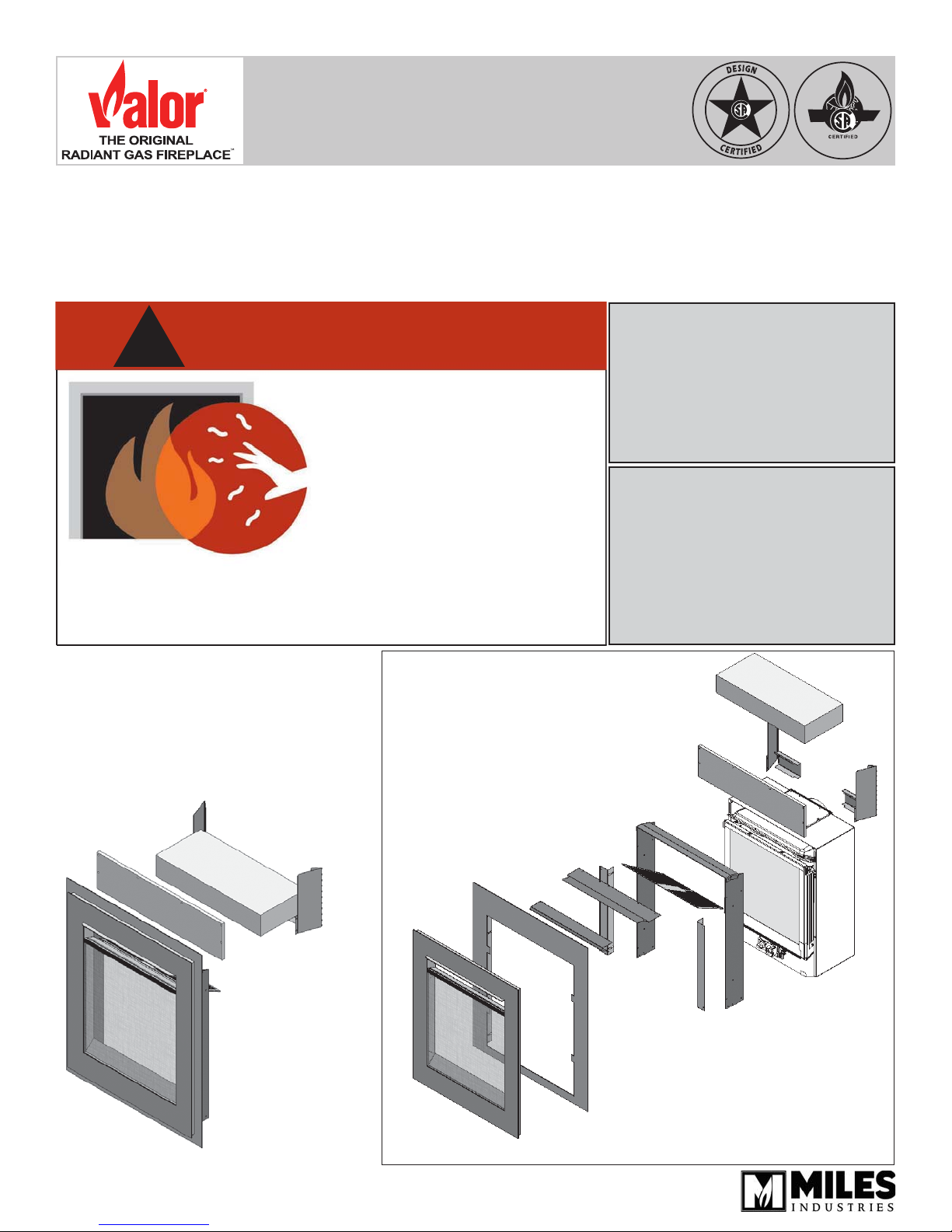
The 546LFB ZC Portrait Ledgeview Front
is designed to be used on the 530 Valor
heaters when installed in a zero clearance
application.
For installation with an insert, use 546LFB
Ledgeview Fronts.
ZC Bae
Heat
exchanger
cover
Hardieboard Panel
Stud brackets (2)
Backing Plate
Insulation
Backing frame
Assembly
Stand o brackets
530 Engine
(sold separately)
4005278-01
©2016, Miles Industries Ltd.
Ledgeview Front with Barrier screen
Overview (530 engine sold separately)
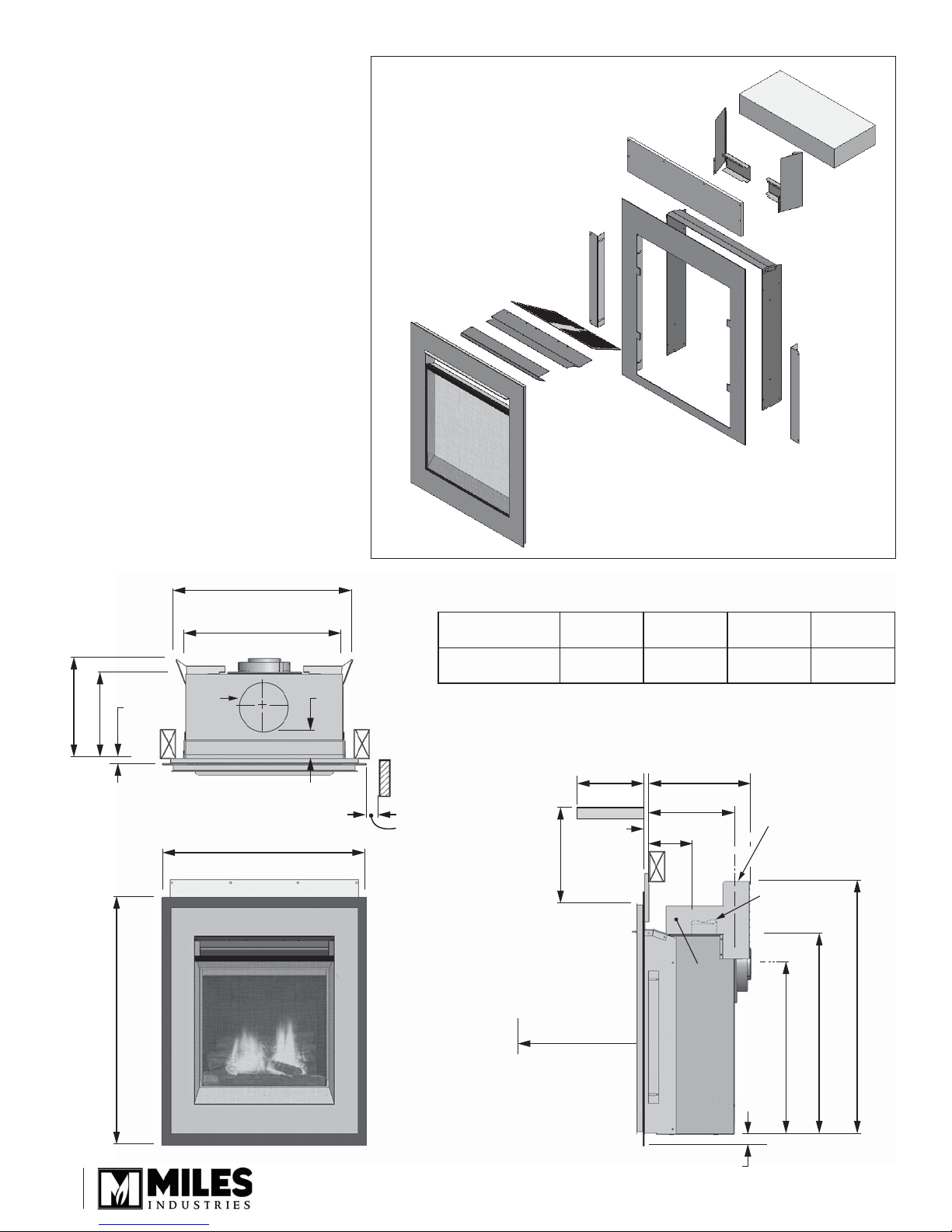
Kit Contents
546 ZC
1 Backing Frame assembly
1 Backing plate
1 Ledgeview Front assembly
1 Heat Exchanger Cover
1 Ceiling Panel
1 ZC Baffl e
1 Barrier Screen (fi tted)
2 Stand Offs
1 Insulation
2 Stud Brackets
1 Cement board
2 Screws #8 x 3/8 tapping pn hd ph
8 Screws #8 x 1/2” black
4 Screws #8 x 1/2” s/t black
Heat
exchanger
cover
ZC bae
Hardieboard
Ceiling
panel
Ledgeview Front with
Barrier screen
Stand o brackets
Backing plate
26”
W x 32-1/8” H
Insulation
Backing frame
assembly
Stud brackets (2)
Dimensions and Clearances
22-7/16”
20”
6-5/8”
dia.
26”
11”
12-3/4”
1-1/2” max.
1/2” min.
32-1/8”
Mantel Clearances
Mantel Depth ‘A’
Mantel Height ‘B’
0–6”
(0–152 mm)8”(203 mm)
4”
(102 mm)8”(203 mm)
4”
12-3/4”
11”
4”
Insulation
2” sidewall minimum
clearance
‘A’
Mantel
1/2”
‘B’
Do not put
furniture or objects
within 36” of front
of appliance
10”
(254 mm)
10”
(254 mm)
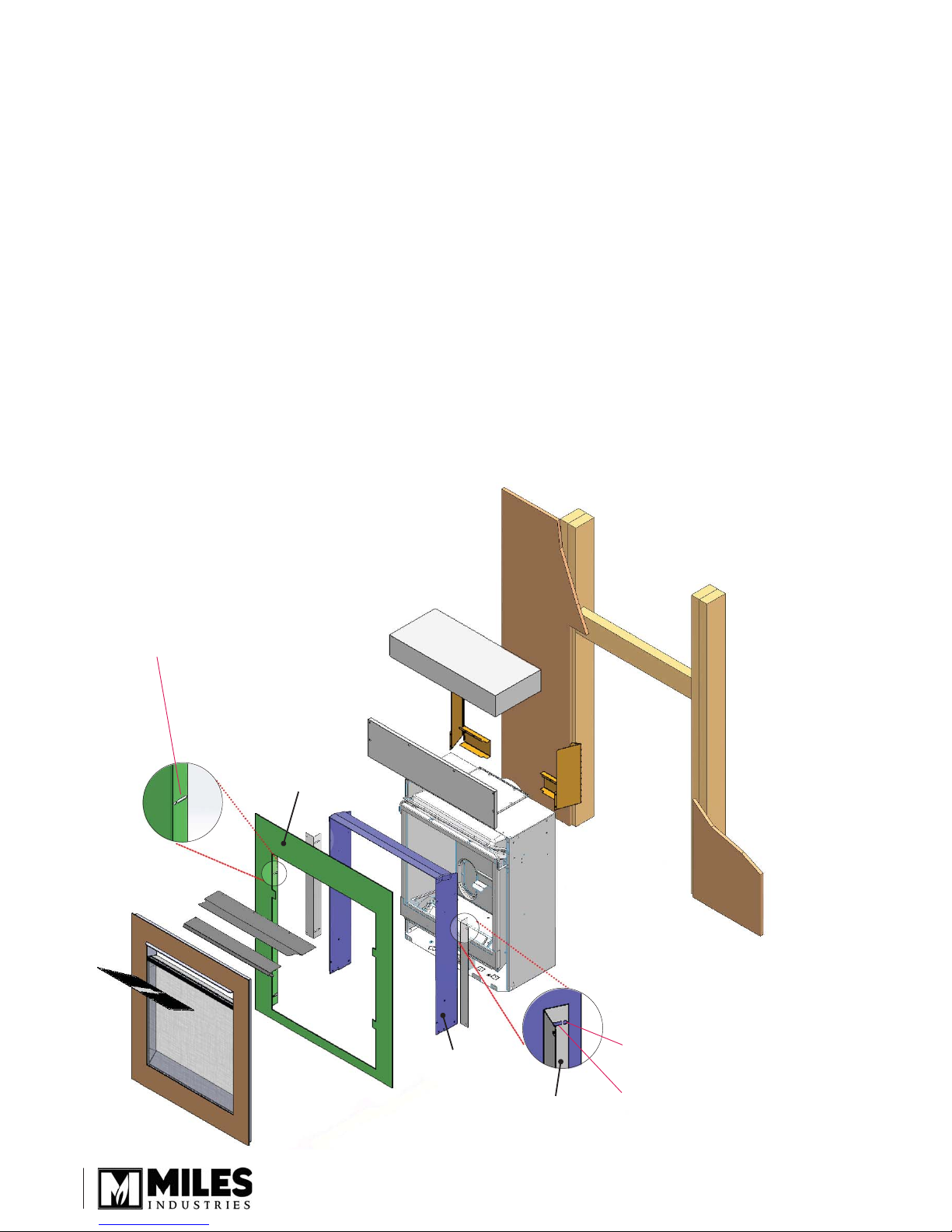
ZC Stand-os
Top
Outlet
21-5/8”
12”
(305 mm)
12”
(305 mm)
32”
25-1/4”
2
1-1/2” between bottom of trim
and bottom of appliance

Corner dimensions
34” (864 mm)
90°
48” (1219 mm)
(305 mm)
12”
Face of
wall studs
Framing
32” (813 mm)
This is the framing
width. Drywall to
24” (610 mm) wide
(to edge of stud brackets)
to header
22-1/2”
(572 mm)
Minimum 12-3/4” (324 mm)
(Allow extra if using rear vent elbow)
Wall Finish
6-1/8” (154 mm)
cement board
supplied
Note There is a 1” (25 mm)
gap between bottom
of cement board and
top of backing frame
assembly
26-7/8” (684 mm)
to cement board
Note Finished surface of floor
or hearth/shelf, if used,
must be min. 1-1/2”
lower than bottom of
appliance otherwise the
front trim will not fit
3
Adjustability of the Clearview Front ZC
• Method 1. The appliance’s position within the
framing cavity may be adjusted forward in the
framing up to 1” to accomodate additional wall fi nish
thickness “tucked” behind the backing plate.
• Method 2. The Backing Plate is also adjustable to
accomodate up to an additional 3/4” of tile or other
non-combustible material over top of the 1/2” noncombustible wall board.
• Method 1 and Method 2 may be combined for a total
of 1-3/4” of non-combustible material over top of the
1/2” wall board.
Attention! When positioning the appliance forward
of the framing cavity (Method 1), ensure that the front
edge of the backing frame does not protrude beyond
the planned fi nished wall surface. Otherwise the
backing plate, when installed, will not sit against the
fi nished wall.
Method 2 - Backing Plate Positioning
Backing Plate is adjustable up to 3/4”.
Backing Plate
Backing frame
assembly
Stud bracket
Method 1 - Appliance Positioning
Measured from face of stud
bracket to front edge of backing
plate frame assembly
Wall nish thickness: 1/2”
- use hole
Wall nish thickness: 1/2” to 1-1/2”
- use slot
4
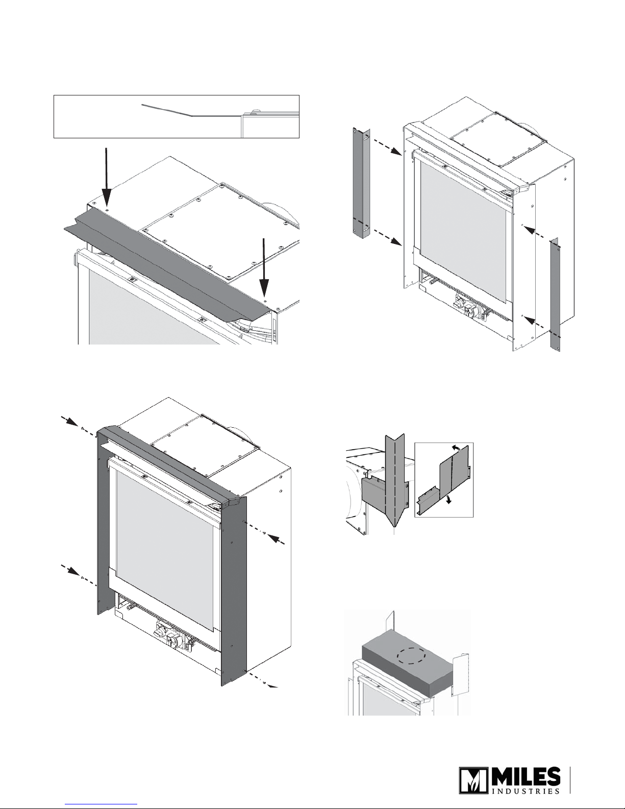
Installation
1. Fit the ZC baffl e under the top panel of the
appliance case. Secure as shown with 2 thread
forming screws provided.
ZC baffl e orientation
—side view
3. Install stud brackets over top of the backing plate
frame assembly with 2 screws per side.
See Adjustability of the Ledgeview Front ZC section
for more information on position of brackets.
2. Slide the backing plate frame assembly over
the appliance case and secure it with 4 screws
provided.
4. Required for installation in combustible
construction. Bend the stand-offs into shape and
fi x them to the appliance’s case as indicated (4
screws/side, pre-fi tted on engine).
5. Required for installation in combustible
construction. Add insulation pad on the top of the
appliance, cutting around the pipe if installing a top
vent.
5
 Loading...