

Valor 541, 541 Dream, 541 Excelsior Installer And Owner Manual
© GDC Group Ltd. 2014
5133673/06
INSTALLER: Please leave this guide with the owner
Model 541
ROOM SEALED RADIANT / CONVECTOR
GAS FIRE
Fitted with one of the following fascia’s.
Dream, Masquerade or
Excelsior
(GC No. 32-032-65)
We trust that this guide gives
sufficient details to enable this
appliance to be installed,
operated and maintained
satisfactorily. However, if
further information is required,
our Valor Technical Helpline
will be pleased to help.
Telephone 0844 879 35 88
(National call rates apply in the
United Kingdom).
In the Republic of Ireland
Telephone 01 842 8222.
INSTALLER AND OWNER GUIDE
DON’T FORGET
To register your guarantee!
Call 0800 597 8500
© GDC Group Ltd.
All rights reserved. No part of this publication may be reproduced in any material form
(including photocopying), stored in any medium by electronic means (including in any
retrieval system or database) or transmitted, in any form or by any means, whether
electronic, mechanical, recording or otherwise, without the prior written permission of
the copyright owner.
Applications for the copyright owner's permission to reproduce any part of this
publication should be made, giving details of the proposed use, to the following
address: The Marketing Communications Manager, GDC Group Ltd, Millbrook House,
Grange Dive, Hedge End, Southampton, SO30 2DF.
Warning: Any person who does any unauthorised act in relation to a copyright work
may be liable to criminal prosecution and civil claims for damages.
Valor, GDC Group Ltd, Millbrook House, Grange Dive,
Hedge End, Southampton, SO30 2DF.
www.valor.co.uk
Because our policy is one of constant development and improvement, details may vary
slightly from those given in this publication
Page 2
© GDC Group Ltd. 2014
THIS APPLIANCE IS FOR USE WITH NATURAL GAS (G20).
UNDER NO CIRCUMSTANCES IS THIS FIRE TO BE CONVERTED TO LPG.
AN LPG KIT DOES NOT EXIST FOR THIS GAS FIRE.
THIS APPLIANCE IS SUITABLE ONLY FOR INSTALLATION IN THE UNITED
KINGDOM (GB) AND THE REPUBLIC OF IRELAND (IE).
Page 3
Safety First.
Valor Fires fires are CE Approved and designed to meet the appropriate British
Standards and Safety Marks.
Quality and Excellence.
All Valor Fires fires are manufactured to the highest standards of quality and
excellence and are manufactured under a BS EN ISO 9001 quality system accepted
by the British Standards Institute.
The Highest Standards
Valor Fires is a member of SBGI and HHIC (Heating and Hot water Industry Council)
that work to ensure high standards of safety, quality and performance.
Careful Installation
This gas fire must be installed by a competent GAS SAFE REGISTER engineer
(GAS SAFE REGISTER or CORGI engineer outside of UK) in accordance with our
installer guide and should not be fitted directly on to a carpet.
© GDC Group Ltd. 2014

Page 4
© GDC Group Ltd. 2014
INSTALLER GUIDE
FOR OWNER GUIDE SEE PAGES 47 TO 59
INSTALLER GUIDE

CONTENTS
Section Heading Page
INSTALLER GUIDE 4 - 46
OWNER GUIDE 47 - 59
1. SAFETY 7
2. APPLIANCE DATA, EFFICIENCY AND NOx 8
2.1 General information. 8
2.2 Efficiency. 9
3. LIST OF AVAILABLE KITS 9
4. APPLIANCE AND RECESS DIMENSIONS 10
5. GENERAL INSTALLATION REQUIREMENTS 12
5.1 Regulations, Standards and Law. 12
5.1.1 Considerations for timber framed buildings. 12
5.2 Ventilation requirements. 12
5.3 Fireguard requirements. 13
5.4 Room considerations. 13
5.5 Fireplace preparation. 13
5.6 The surround. 13
5.7 Hearth / plinth requirements. 14
5.8 Fireplace clearances. 15
5.9 Installation options. 16
5.10 Terminal guard and terminal clearances. 16
6. UNPACKING AND PRELIMINARY CHECKS 18
6.1 Unpacking. 18
6.2 Appliance disassembly. 19
6.3 Preliminary checks. 20
7. GAS SUPPLY CONNECTION 21
8. WALL PREPARATION 22
8.1 Select appliance position. 22
8.2 Constructing a recessed opening. 22
8.2.1 Fitting a lintel. 22
8.2.2 Preparing a wall cavity. 23
8.3 Combustible wall materials. 23
8.4 Cutting the flue hole for brick, stone etc. building. 24
8.5 Cutting the flue hole in timber frame buildings. 24
8.6 Prepare appliance fixing holes. 26
Page 5
© GDC Group Ltd. 2014
INSTALLER GUIDE
Continued on next page

Section Heading Page
9. FLUE TERMINAL INSTALLATION 26
9.1 Cutting flue to size. 26
9.2 Fitting to wall. 28
9.3 Fitting the terminal guard. 29
10. GAS CONNECTION 29
11. CERAMIC COALS INSTALLATION 30
12. CERAMIC PEBBLES INSTALLATION 32
13. WINDOW FITTING 34
14. FULL OPERATING CHECKS 34
14.1 Check for leaks. 34
14.2 Check control operation. 34
14.3 Checking inlet pressure. 35
15. FASCIA FITTING 36
15.1 Fitting the Masquerade fascia 36
15.2 Fitting the Excelsior fascia. 37
15.3 Fitting the Dream fascia. 38
16. FINAL REVIEW 39
17. SERVICING & PARTS REPLACEMENT 40
17.1 To remove the fascia. 40
17.2 To remove or clean the window unit. 42
17.3 To remove the ceramic fuel effect and rear wall. 43
17.4 To replace the ceramic fuel effect. 43
17.5 To remove the complete burner module. 43
17.6 To remove the burner from the burner module. 44
17.7 To remove the injector. 44
17.8 To remove the pilot unit. 44
17.9 To remove the gas valve. 45
17.10 To remove the switch and wiring loom. 45
Page 6
© GDC Group Ltd. 2014
INSTALLER GUIDE
CONTENTS (Continued)

1. SAFETY
Installer
Before continuing any further with the installation of this appliance please read the
following guide to manual handling:
- The approximate lifting weight (kg) of this appliances are as below:
Model
Heat Engine Fascia / Fire front Combined Weight
Dream 12.3 13.1 25.4
Masquerade 12.3 12.1 24.4
Excelsior 12.3 12.6 24.9
- One person should be sufficient to lift the fire. If for any reason this weight is
considered too heavy then obtain assistance.
- When lifting always keep your back straight. Bend your legs and not your back.
- Avoid twisting at the waist. It is better to reposition your feet.
- Avoid upper body/top heavy bending. Do not lean forward or sideways whilst
handling the fire.
- Always grip with the palm of the hand. Do not use the tips of fingers for support.
- Always keep the fire as close to the body as possible. This will minimise the
cantilever action.
- Use gloves to provide additional grip.
- Always use assistance if required.
This product uses a fuel effect, a burner compartment rear wall and gaskets
containing Refractory Ceramic Fibres (RCF), which are man-made vitreous
silicate fibres. Excessive exposure to these materials may cause irritation to
eyes, skin and respiratory tract. Consequently, it is important to take care when
handling these articles to ensure that the release of dust is kept to a minimum.
To ensure that the release of fibres from these RCF articles is kept to a
minimum, during installation and servicing we recommend that you use a HEPA
filtered vacuum to remove any dust and soot accumulated in and around the
fire before and after working on the fire. When replacing these articles we
recommend that the replaced items are not broken up, but are sealed within a
heavy duty polythene bag, clearly labelled as RCF waste. RCF waste is classed
as a stable, non-reactive hazardous waste and may be disposed at a landfill
licensed to accept such waste. Protective clothing is not required when
handling these articles, but we recommend you follow the normal hygiene rules
of not smoking, eating or drinking in the work area and always wash your
hands before eating or drinking. This appliance does not contain any
component manufactured from asbestos or asbestos related products.
Page 7
© GDC Group Ltd. 2014
INSTALLER GUIDE
2. APPLIANCE DATA AND EFFICIENCY.
2.1 General information.
Under no circumstances is this fire to be converted to LPG. An LPG conversion kit
does not exist for this gas fire.
The appliance information label is located on a plate at the base of the fire. This can
be seen by removing the lower front casting / fire front.
Before continuing with the installation of this appliance please complete the
information on the last pages of the owner guide.
Page 8
© GDC Group Ltd. 2014
INSTALLER GUIDE
Gas Natural
Inlet pressure 20mbar
Input - Max. (Gross) 3.65kW (12,454 Btu/h)
Input - Min. (Gross) 1.5kW (5,118 Btu/h)
Inlet pressure (Cold) 20.0 ± 1.0mbar (8.0 ± 0.4in w.g.)
Gas connection 8mm pipe
Main burner Simplex aerated
Burner injector Cat. 92 size 280
Pilot unit
Left side of firebox. Combined pilot jet, thermocouple sensor
and electrode. SIT ref. NGOP9706
Ignition Integral piezo on gas valve.
Aeration adjustment None required
Controls
Manual pilot and main burner off/on control (Right control).
Separate variable control (Left control) for main burner can be
operated by its control knob or from the high level rocker
switch. Fitted with flame supervision device and integral piezo
igniter
Batteries 4 x 1.5V AA
Walls
Minimum 102mm (4in.) thick.
Maximum 660mm (26in.) thick.
2.2 Efficiency.
The efficiency of this appliance has been measured as specified in BS EN 613 and
the result is as below:
Model
Efficiency % (Gross)
541 76
The gross calorific value of the fuel has been used for this efficiency calculation. The
test data from which it has been calculated has been certified by Advantica
Certification services (0087). The efficiency value may be used in the UK
Government's Standard Assessment Procedure (SAP) for energy rating of dwellings.
The conversion of net efficiency to gross was achieved by multiplying the net
efficiency by the following conversion factor from Table E3 of SAP 2005, rounding
down to the nearest whole number.
3. LIST OF AVAILABLE KITS
Description Part number
- Spacer kit (5 inch) 0595121
- Spacer kit (3 inch) 0595131
Page 9
© GDC Group Ltd. 2014
Gas Conversion factor from net to gross efficiency
Natural Gas 0.901
INSTALLER GUIDE

4. APPLIANCE AND RECESS DIMENSIONS
This appliance must not be recessed into a combustible wall.
Page 10
© GDC Group Ltd. 2014
INSTALLER GUIDE
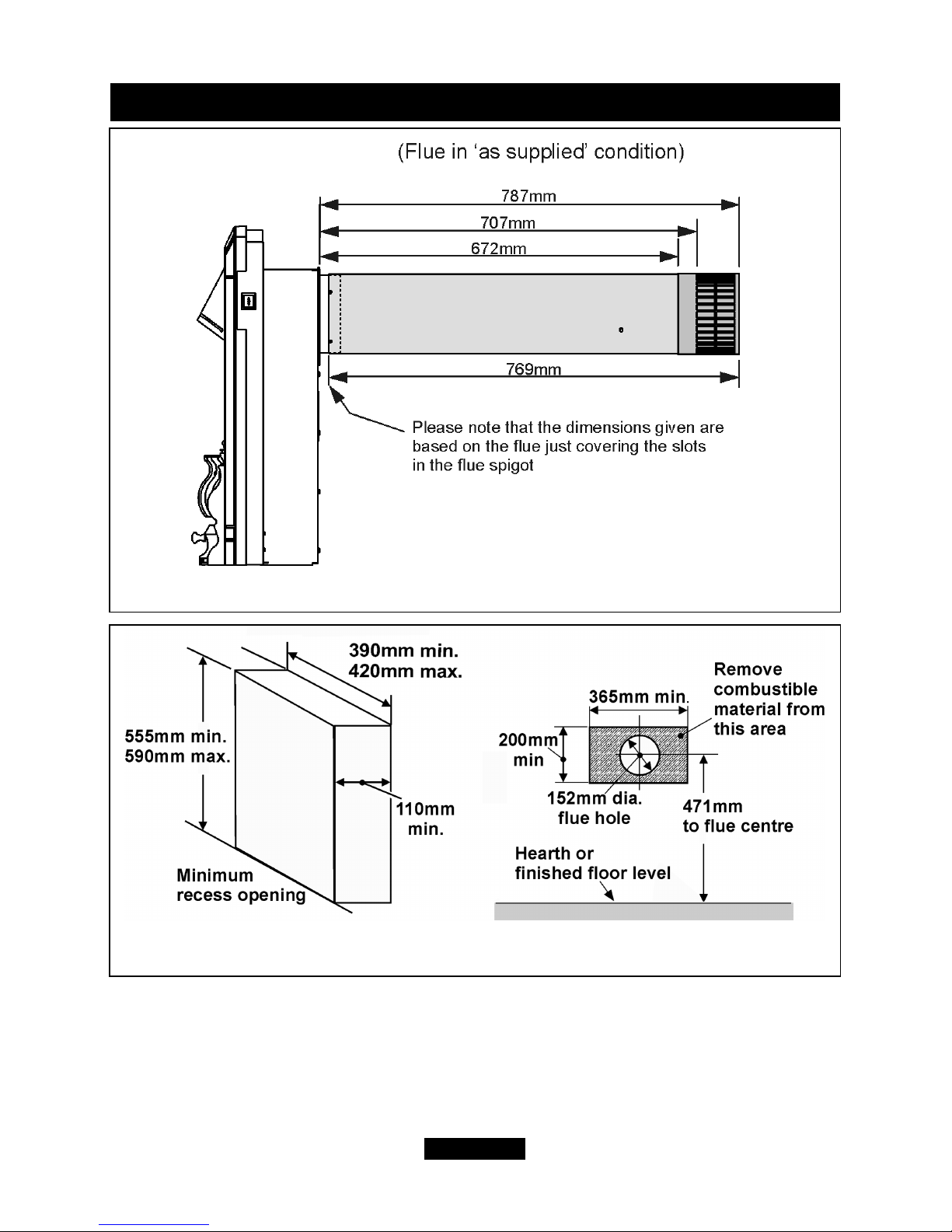
Figure 1. Appliance dimensions and clearances (Fire dimensions are subject to
manufacturing deviation). Fascia may differ from that shown.
Key Description
Model
Masquerade
Excelsior Dream
A Appliance height (mm) 635 635 635
B Appliance width (mm) 518 518 518
C Appliance depth into room (mm) 135 135 135
D
Minimum mandatory clearance to
combustible surfaces projecting
beyond the front of appliance (mm).
102 102 102
E
Recommended clearance to non-
combustible surfaces for access
purposes (mm).
51 51 51
See Figure 4.
Page 11
© GDC Group Ltd. 2014
Figure 2. Recess and flue hole dimensions.
INSTALLER GUIDE
Figure 1 (Continued).

5. GENERAL INSTALLATION REQUIREMENTS
5.1 Regulations, Standards and Law.
The installation must be in accordance with this guide.
For the user’s protection, in the United Kingdom it is the law that all gas appliances
are installed by competent persons in accordance with the current edition of the Gas
Safety (Installation and Use) Regulations. Failure to install the appliance correctly
could lead to prosecution. GAS SAFE REGISTER and CORGI require their members
to work to recognised standards.
In the United Kingdom the installation must also be in accordance with:
All the relevant parts of local regulations.
The relevant parts of the current editions of the following British Standards:BS 5440 Part 1- Installation of flues
BS 5871 Part 1- Installation - Gas fires
BS 6891- Installation of low pressure gas pipework of up to 35mm (R1 ¼) in
domestic premises (2nd family gas) - specification.
- In England and Wales, the current edition of the Building Regulations issued by the
Department of the Environment and the Welsh Office.
- In Scotland, the current edition of the Building Standards (Scotland) Regulations
issued by the Scottish Executive.
- In Northern Ireland, the current edition of the Building regulations (Northern
Ireland) issued by the Department of the Environment for Northern Ireland.
- In the republic of Ireland the installation must be carried out by a competent person
and also conform to the relevant parts of:
a) The current edition of IS 813 “Domestic Gas Installations”
b) All relevant national and local rules in force.
Where no specific instructions are given, reference should be made to the relevant
British Standard Code of Practice.
5.1.1 Considerations for timber framed buildings.
Installation to a timber-framed building should be in accordance with the relevant
sections of The Institute of Gas Engineers publication IGE/UP/7 “Gas installations in
timber frame buildings”.
Please note that advice should be sought before installing in a timber frame building
since the alterations required may nullify any NHBC cover relating to the property. If
in doubt, guidance should be requested from your local authority planning or building
department.
Under no circumstances is the fire to be recessed into timber frame
constructions. For timber framed installations see section 8.
5.2 Ventilation requirements.
No special ventilation bricks or vents are required into the room containing the
appliance.
Page 12
© GDC Group Ltd. 2014
INSTALLER GUIDE
5.3 Fireguard requirements.
A fireguard complying with BS 8423 should be fitted for the protection of young
children, the elderly, the infirm and pet animals.
5.4 Room considerations.
5.4.1 This appliance has exposed battery and electric motor components. It is not
recommended, therefore, that it be used in rooms which contains a bath, shower or
where steam is regularly present due to the possibility of corrosion or electrical
shorting.
5.4.2 Note that soft wall coverings (e.g. embossed vinyl etc.) are easily affected by
heat. They may therefore, scorch or become discoloured when close to a heating
appliance. Please bear this in mind when installing.
5.4.3 It is advisable that combustible fabrics such as curtains are not fitted above the
fire. If, however, this is unavoidable, the extreme bottom edge of the fabric must be at
least 780mm above the base of the fire.
5.5 Fireplace preparation.
5.5.1 The front face of the fireplace should be reasonably flat over the area covered
by the convection box top and side flange seals to ensure good sealing. These faces
should be made good if necessary. The fireplace floor should be reasonably flat to
ensure that a good seal with the convection box can be made.
5.5.2 A hole 152mm (6in) dia. is required through the wall for the flue unit. The height
of the hole centre is shown in figure 2 and on the wall-fixing template supplied with
the appliance.
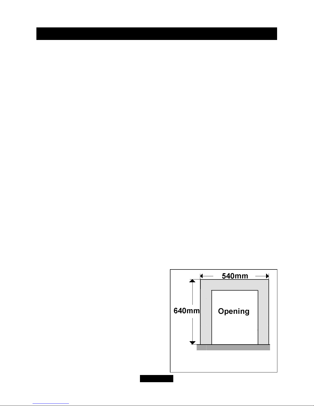
5.5.3 Combustible cladding.
Masquerade/Excelsior and Dream models.
If the fire is to be fitted against a wall with
combustible cladding, the cladding must be
removed from the area shown in
figure 3.
5.6 The surround.
The appliance can be fitted to a purpose made
proprietary class “O” 150°C surround. We
recommend that the surround manufacturer is
contacted to confirm compatibility.
Page 13
© GDC Group Ltd. 2014
INSTALLER GUIDE
Figure 3. Area to be free of
combustible cladding.

5.7 Hearth / plinth requirements.
For installations that are elevated and recessed.
The Dream/Masquerade/Excelsior models are fitted with a fire front casting
set that is not secured to the fire. It will therefore be necessary for a hearth / plinth to
be fitted. The recommended minimum depth of the hearth / plinth from the fixing
plane of the fire is 100mm.
For installations that are not elevated.
This appliance does not require a non-combustible hearth. It can be installed on
any hard surface. This surface should be level and sufficiently flat to enable the
bottom of the fascia / fire front casting to be aligned horizontally. Any unevenness
(Uneven tiles, Cotswold stone etc.) should be rectified.
The appliance must not stand on carpet or other textured surfaces which may
interfere with the flow of convection air through the bottom of the appliance.
The floor surface that must be free of carpets, rugs or other fabric coverings should
be at least as wide as the appliance fascia and project forward at least 300mm from
the rear wall. In order to prevent carpet etc. being placed within this area, we strongly
recommend that the appliance is installed on a raised hearth or that the periphery of
this area is bordered by a fender.
Page 14
© GDC Group Ltd. 2014
INSTALLER GUIDE
5.8 Fireplace clearances.
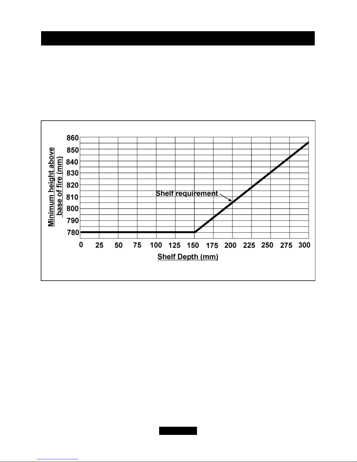
5.8.1 The minimum height from the base of the fire to the underside of any shelf
made from wood or other combustible materials is as follows:-
• For a shelf up to 150mm deep
Minimum height = 780mm.
• For a shelf deeper than 150mm
780mm + 12.5mm for every 25mm depth over 150mm.
(See figure 4)
There is no restriction on the position or depth of non-combustible projections for all
normal installations. Installation into an unusually tightly restricted recess, however,
could cause the temperature of the appliance surfaces to become unacceptably high.
5.8.2 A minimum clearance of 51mm should be maintained at each side of the fire for
servicing access.
Any combustible side wall or other combustible projection must be at least 102mm
clear from direct exposure to the radiant surface of the appliance unless suitably
protected.
Page 15
© GDC Group Ltd. 2014
INSTALLER GUIDE
Figure 4. Combustible shelf clearances.

5.9 Installation options.
5.9.1 The appliance can be installed into the following:
a) A minimum 4.5 inch rebate surround or 5 inch spacer kit Part No 0595121.
Where either of these are mounted to a combustible wall make sure that there is no
combustible material or combustible cladding in the area indicated on the wall fixing
template.
b) A 2 inch rebate surround in conjunction with the 3 inch spacer kit Part No
0595131. Where the surround is mounted to a combustible wall make sure that there
is no combustible material or combustible cladding in the area indicated on the wallfixing template.
c) Recessed into a builder’s opening or cavity of a non- combustible wall. The
minimum cavity size is shown in figure 2. The cavity can be elevated. A lintel may be
required above the recess opening. If in doubt seek expert building advice. Lintel
construction details are given in section 8 of this guide.
This appliance must not be recessed into a combustible wall.
5.9.2 A concealed gas supply connection can be made through the rear left panel.
Visible front connection can be from the left or right side.
5.10 Terminal guard and terminal clearances.
5.10.1 A terminal guard is supplied with this appliance.
In England and Wales the Building Regulations require a terminal guard to be fitted if
the terminal could come into contact with people near the building or be subject to
damage.
In the republic of Ireland the installation must also conform to the relevant parts of the
current edition of IS 813 “Domestic Gas Installations”
We recommend that the guard is fitted where contact with or damage to the terminal
is possible even if regulations do not demand it.
5.10.2 Minimum allowable distances from the terminal are shown in figures 5 and 6.
Page 16
© GDC Group Ltd. 2014
INSTALLER GUIDE
*In addition, the terminal should not be nearer than 300mm to an opening in the
building fabric formed for the purpose of accommodating a built-in element such as a
window frame or door frame (See figure 6).
** The reference to external corners does not apply to building protrusions not
exceeding 450mm, such as disused chimneys on external walls.
Page 17
© GDC Group Ltd. 2014
INSTALLER GUIDE
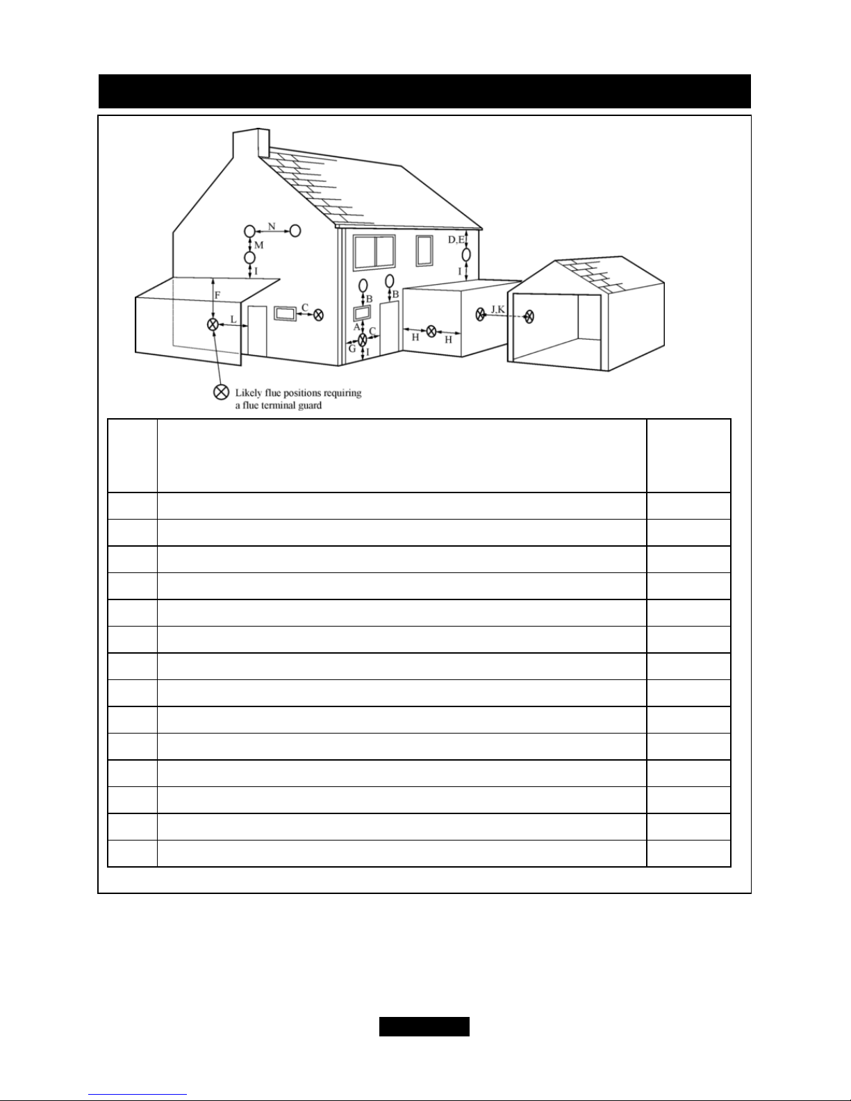
Key Terminal position
Minimum
distance
(mm)
A* Directly below an opening, air brick, opening window etc. 300mm
B* Above an opening, air brick, opening window etc. 300mm
C* Horizontally to an opening, air brick, opening window etc. 300mm
D Below gutters, soil pipes or drain pipes. 300mm
E Below eaves. 300mm
F Below balconies or car port roof. 600mm
G From a vertical drain pipe or soil pipe. 300mm
H** From an internal or external corner. 600mm
I Above ground, roof or balcony level. 300mm
J From a surface facing the terminal. 600mm
K From a terminal facing the terminal. 600mm
L From an opening in a car port (e.g. door, window) into dwelling. 1200mm
M Vertically from a terminal on the same wall. 1500mm
N Horizontally from a terminal on the same wall. 300mm
Figure 5.
 Loading...