

Valor 534XAN, 534XAP, 535XAN, 535XAP Installation & Operating Instructions Manual
Model 534XAN (Natural Gas)
Model 534XAP (Propane)
Direct Vent Gas Fireplace Heater
Installation & Operating Instructions
INSTALLER: Leave this manual with the appliance.
CONSUMER: Retain this manual for future reference.
Please read this manual BEFORE installing and operating this appliance.
WARNING: If the information in these
instructions is not followed exactly, a fi re
or explosion may result causing property
damage, personal injury or loss of life.
Do not store or use gasoline or other
fl ammable vapors and liquids in the vicinity
of this or any other appliance.
WHAT TO DO IF YOU SMELL GAS
• Do not try to light the appliance.
• Do not touch any electrical switch; do not
use any phone in your building.
• Immediately call your gas supplier from
a neighbor’s phone. Follow the gas
supplier’s instructions.
• If you cannot reach your gas supplier, call
the fi re department.
Installation and service must be performed
by a qualifi ed installer, service agency or the
gas supplier.
This appliance may be installed in an
after-market permanently located,
manufactured (mobile) home where not
prohibited by local codes.
This appliance is only for use with the type
of gas indicated on the rating plate. This
appliance is not convertible for use with
other gases, unless a certifi ed kit is used.
This appliance is a domestic room-heating
appliance. It must not be used for any other
purposes such as drying clothes, etc.
This appliance is suitable for installation in a
bedroom or bed sitting room.
Massachusetts: The piping and fi nal
gas connection must be performed by a
licensed plumber or gas fi tter in the State of
Massachusetts. Also, see Carbon Monoxide
Detector requirements under “Safety and
Warning Information” on page 5.
4000307-13
Manufactured by
MILES INDUSTRIES LTD.
British Columbia, Canada
www.milesfi replaces.com
Thank You ...
For purchasing a Valor by Miles Industries. Your new radiant gas heater is a technical
appliance that must be installed by a qualifi ed dealer. Each Valor fi replace is fully
tested during the production process for your safety and comfort.
Your unit has been professionally installed by:
Dealer Name _______________________________________
Phone Number ______________________________________
Should you encounter an operational problem, call your dealer immediately.
Do not try to repair the unit as you may cause an injury or damage the fi replace.
The information contained in this installation manual is believed to be correct at
the time of printing. Miles Industries Ltd. reserves the right to change or modify any
information or specifi cations without notice. Miles Industries Ltd. grants no warranty,
implied or stated, for the installation or maintenance of your heater, and assumes no
responsibility for any consequential damage(s).
We recommend that our gas
hearth products be installed
and serviced by professionals
who are certifi ed in the United
States by NFI (National Fireplace
Institute®).
190 – 2255 Dollarton Highway, North Vancouver B.C., CANADA. V7H 3B1
2
2
WARNING
HOT GLASS WILL
CAUSE BURNS.
DO NOT TOUCH GLASS
UNTIL COOLED.
NEVER ALLOW CHILDREN
TO TOUCH GLASS.
Designed and Manufactured by / for
Miles Industries Ltd.
Tel. (604) 984-3496 Fax (604) 984-0246
www.milesfi replaces.com
© Copyright Miles Industries Ltd., 2008

Table of Contents
Safety and Warning Information ..............................................................4
Options .......................................................................................................7
Dimensions ................................................................................................8
Specifi cations ............................................................................................9
Location ....................................................................................................10
Recessed Insert Applications ................................................................17
Horizontal Termination Locations ..........................................................18
Supply Gas ...............................................................................................19
Pack Contents..........................................................................................19
Appliance Preparation ............................................................................21
Installations with Horizontal Termination—Installing to Wall .............26
Installations with Vertical Termination—Through the Roof ................28
Remote Control Installation ....................................................................29
Gas Supply Installation ...........................................................................30
Aeration Setting Check ...........................................................................30
Ceramic Fuel Bed Installation ................................................................31
Window Refi tting & Checking ................................................................32
Operation Checks ....................................................................................32
Front Installation .....................................................................................33
Owner’s Information ................................................................................34
Lighting Instructions ...............................................................................38
Approved Venting Components .............................................................39
Warranty ...................................................................................................41
33

Safety and Warning Information
READ and UNDERSTAND all instructions carefully before
starting the installation. FAILURE TO FOLLOW these
installation instructions may result in possible fi re hazard
and will void the warranty.
Prior to the fi rst fi ring of the fi replace, READ the Owner’s
Information section of this manual.
DO NOT USE this appliance if any part has been under
water. Immediately, CALL a qualifi ed service technician
to inspect the unit and to replace any part of the control
system and any gas control that has been under water.
THIS UNIT IS NOT FOR USE WITH SOLID FUEL.
Installation and repair should be PERFORMED by a
qualifi ed service person. The appliance and venting
system should be INSPECTED before initial use and at
least annually by a professional service person. More
frequent cleaning may be required due to excessive lint
from carpeting, bedding, etc. It is IMPERATIVE that the
unit’s control compartment, burner, and circulating air
passageways BE KEPT CLEAN to provide for adequate
combustion and ventilation air.
Always KEEP the appliance clear and free from
combustible materials, gasoline, and other fl ammable
vapors and liquids.
NEVER OBSTRUCT the fl ow of combustion and
ventilation air. Keep the front of the appliance CLEAR
of all obstacles and materials for servicing and proper
operation.
Due to the high temperature, the appliance should be
LOCATED out of traffi c areas and away from furniture and
draperies. Clothing or fl ammable material SHOULD NOT
BE PLACED on or near the appliance.
Children and adults should be ALERTED to the hazards
of high surface temperature and should STAY AWAY to
avoid burns or clothing ignition. Young children should be
CAREFULLY SUPERVISED when they are in the same
room as the appliance.
This gas fi replace and vent assembly MUST be vented
directly to the outside and MUST NEVER be attached to a
chimney serving a separate solid fuel burning appliance.
Each gas appliance MUST USE a separate vent system.
Common vent systems are PROHIBITED.
INSPECT the external vent cap on a regular basis to
make sure that no debris, plants, trees, shrubs are
interfering with the air fl ow.
The glass door assembly MUST be in place and sealed
before the unit can be placed into safe operation.
DO NOT OPERATE this appliance with the glass door
removed, cracked, or broken. Replacement of the glass
door should be performed by a licensed or qualifi ed
service person. DO NOT strike or slam the glass door.
The glass door assembly SHALL ONLY be replaced as a
complete unit, as supplied by the fi replace manufacturer.
NO SUBSTITUTE material may be used.
DO NOT USE abrasive cleaners on the glass door
assembly. DO NOT ATTEMPT to clean the glass door
when it is hot.
TURN OFF the gas before servicing this appliance. It is
recommended that a qualifi ed service technician perform
an appliance check-up at the beginning of each heating
season.
Any safety screen or guard removed for servicing MUST
BE REPLACED before operating this appliance.
DO NOT place furniture or any other combustible
household objects within 36” of the fi replace front.
BE CAREFUL not to put any decorating objects sensitive
to heat too close near or above the fi replace as it gets
very hot when operating.
DO NOT use this heater as a temporary source of heat
during construction.
This unit MUST be used with a vent system as described
in this installation manual. NO OTHER vent system or
components MAY BE USED.
NOTE: When operating your new fi replace for the fi rst time, some vapors may be released due to the burning of curing
compounds used in the manufacture of the appliance. They may cause a slight odor and could cause the fl ames to be the
full height of the fi rebox, or even slightly higher, for the fi rst few hours of operation. It is also possible that these vapors
could set off any smoke detection alarms in the immediate vicinity. These vapors are quite normal on new appliances. We
recommend opening a window to vent the room. After a few hours use, the vapors will have disappeared and the fl ames
will be at their normal height.
44

Safety and Warning Information
State of California. Proposition 65 Warning. Fuels used in gas, wood-burning or oil fi red appliances, and the products
of combustion of such fuels, contain chemicals known to the State of California to cause cancer, birth defects and other
reproductive harm. California Health & Safety Code Sec. 25249.6.
State of Massachusetts Carbon Monoxide Detector/Vent Terminal Signage Requirements
For all side wall horizontally vented gas fueled equipment installed in every dwelling, building or structure used in whole or
in part for residential purposes, including those owned or operated by the Commonwealth and where the side wall exhaust
vent termination is less than seven (7) feet above fi nished grade in the area of the venting, including but not limited to
decks and porches, the following requirements shall be satisfi ed:
1. INSTALLATION OF CARBON MONOXIDE DETECTORS. At the time of installation of the side wall horizontal vented
gas fueled equipment, the installing plumber or gas fi tter shall observe that a hard wired carbon monoxide detector with
an alarm and battery back-up is installed on the fl oor level where the gas equipment is to be installed. In addition, the
installing plumber or gas fi tter shall observe that a battery operated or hard wired carbon monoxide detector with an
alarm is installed on each additional level of the dwelling, building or structure served by the side wall horizontal vented
gas fueled equipment. It shall be the responsibility of the property owner to secure the services of qualifi ed licensed
professionals for the installation of hard wired carbon monoxide detectors.
a. In the event that the side wall horizontally vented gas fueled equipment is installed in a crawl space or an attic, the hard
wired carbon monoxide detector with alarm and battery back-up may be installed on the next adjacent fl oor level.
b. In the event that the requirements of this subdivision can not be met at the time of completion of installation, the owner
shall have a period of thirty (30) days to comply with the above requirements; provided, however, that during said thirty
(30) day period, a battery operated carbon monoxide detector with an alarm shall be installed.
2. APPROVED CARBON MONOXIDE DETECTORS. Each carbon monoxide detector as required in accordance with the
above provisions shall comply with NFPA 720 and be ANSI/UL 2034 listed and IAS certifi ed.
3. SIGNAGE. A metal or plastic identifi cation plate shall be permanently mounted to the exterior of the building at a
minimum height of eight (8) feet above grade directly in line with the exhaust vent terminal for the horizontally vented gas
fueled heating appliance or equipment. The sign shall read, in print size no less than one-half (1/2) inch in size, “GAS
VENT DIRECTLY BELOW. KEEP CLEAR OF ALL OBSTRUCTIONS”.
4. INSPECTION. The state or local gas inspector of the side wall horizontally vented gas fueled equipment shall not
approve the installation unless, upon inspection, the inspector observes carbon monoxide detectors and signage installed
in accordance with the provisions of 248 CMR 5.08(2)(a)1 through 4.
(b) EXEMPTIONS: The following equipment is exempt from 248 CMR 5.08(2)(a)1 through 4:
1. The equipment listed in Chapter 10 entitled “Equipment Not Required To Be Vented” in the most current edition of NFPA
54 as adopted by the Board; and
2. Product Approved side wall horizontally vented gas fueled equipment installed in a room or structure separate from the
dwelling, building or structure used in whole or in part for residential purposes.
(c) MANUFACTURER REQUIREMENTS - GAS EQUIPMENT VENTING SYSTEM PROVIDED. When the manufacturer
of Product Approved side wall horizontally vented gas equipment provides a venting system design or venting system
components with the equipment, the instructions provided by the manufacturer for installation of the equipment and the
55

Safety and Warning Information
venting system shall include:
1. Detailed instructions for the installation of the venting system design or the venting system components; and
2. A complete parts list for the venting system design or venting system.
(d) MANUFACTURER REQUIREMENTS - GAS EQUIPMENT VENTING SYSTEM NOT PROVIDED. When the
manufacturer of a Product Approved side wall horizontally vented gas fueled equipment does not provide the parts
for venting the fl ue gases, but identifi es “special venting systems”, the following requirements shall be satisfi ed by the
manufacturer:
1. The referenced “special venting system” instructions shall be included with the appliance or equipment installation
instructions; and
2. The “special venting systems” shall be Product Approved by the Board, and the instructions for that system shall
include a parts list and detailed installation instructions.
(e) A copy of all installation instructions for all Product Approved side wall horizontally vented gas fueled equipment, all
venting instructions, all parts lists for venting instructions, and/or all venting design instructions shall remain with the
appliance or equipment at the completion of the installation.
66

Options
Heater engine unit #534XAN is used with all natural gas installations.
Heater engine unit #534XAP is used with all propane gas installations.
Optional features
Circulating Fan Kit #755CFK
Having variable speed and temperature control, it is designed to boost the natural convection process through the
appliance. It may be fi tted before the fi replace is installed or retrofi tted at a later date.
Natural Gas Conversion Kit #607NGK
For conversion from propane to natural gas. Intended primarily for post installation conversion in areas where natural gas
was not available at the time of initial installation.
Venting options
Direct vent installations (solid piping)
A list of all approved venting accessories is shown on pages 39–40 of this manual.
Direct Vent Co-Linear Installations (fl exible piping)
Converts the appliance outlet collars to accept two 3” dia. fl ex liners for installation into existing solid fuel burning
fi replaces and chimneys. Requires a co-linear adapter at the appliance and either a co-linear terminal or co-linear-to-co-
axial adapter and terminal at the top of the chimney. A list of approved venting accessories is shown on pages 39–40 of
this manual.
77
29-3/4” (756 mm)
32-3/16” (817 mm)
To side wall from inner frame
3” (75 mm) min.
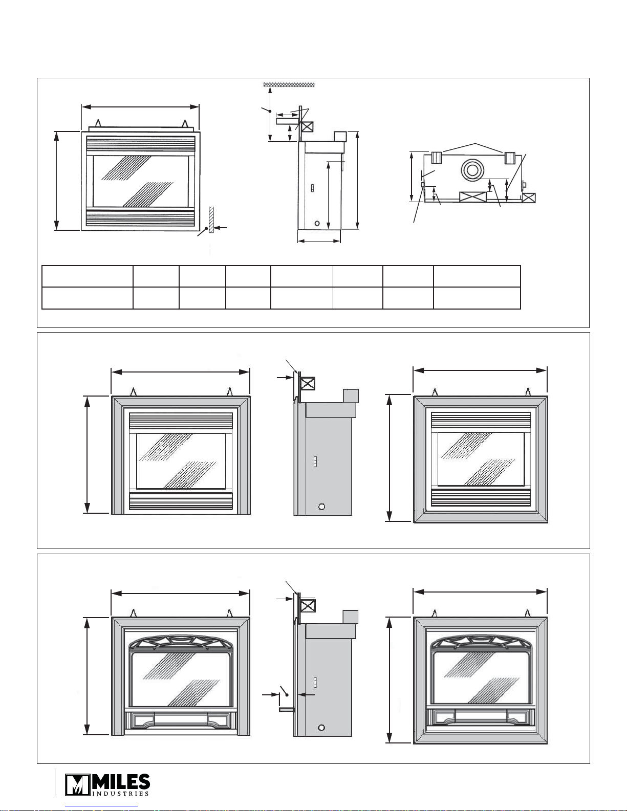
Dimensions
36”
(914 mm)
min.
A
Mantel
B
See table
14”
(355 mm)
23-1/8” (587 mm)
to rear vent center
33-1/2” (850 mm)
16” (406 mm)
(114 mm)
Stand-offs
1-1/2
(38 mm)
4-1/2”
Stand-offs
2” (50 mm) min.
From combustible
framing to vent
7” (180 mm)
From finished
wall front
to top vent
Mantel depth “A”
Mantel clearance “B”
1”
(25 mm)2”(51 mm)3”(76 mm)
7”
(178 mm)8”(203 mm)9”(229 mm)
4”–5”
(102–127 mm)6”(152 mm)7”(178 mm)
10”
(254 mm)
11”
(279 mm)
12”
(305 mm)
Figure 1 Major dimensions & clearances without optional trims (shows with #601SFB Front)
Finished wall
(See Location section-Framing)
34-7/8” (887 mm)
31-1/8” (780 mm)
3/4”
(19 mm)
32-1/2” (825 mm)
3-sided trims
Figure 2 #601SFB Front with optional trims
Finished wall
(See Location section-Framing)
34-7/8” (887 mm)
3/4”
(19 mm)
8”–12” Max.
(203–305 mm) Max.
14”
(356 mm)
34-7/8” (887 mm)
4-sided trims
34-7/8” (887 mm)
31-1/8” (780 mm)
3-sided trims
Figure 3 #602CFB Front with optional trims
88
2-1/8”
(53 mm)
32-1/2” (825 mm)
4-sided trims

Specifi cations
Approvals & codes
These appliances are certifi ed by ANSI Z21.88-2007 / CSA 2.33-2007 Vented Gas Fireplace Heater for use in Canada
and USA. These appliances are for installation directly venting through an outside wall or through the roof.
Model 534XAN is for use with natural gas.
Model 534XAP is for use with propane gas. It can be converted for use with natural gas with kit #607NGK.
These appliances comply with CGA P.4.1 Testing method for measuring annual fi replace effi ciencies.
The installation must conform with local codes or, in the absence of local codes with the National Fuel Gas Code, ANSI
Z223.1 or the Natural Gas and Propane Installation Code CAN/CGA-B149. Only qualifi ed licensed or trained personnel
should install these appliances.
These appliances, when installed, must be electrically grounded in accordance with local codes or, in the absence of local
codes, with the National Electrical Code, ANSI/NFPA 70 or the Canadian Electrical Code, CSA C22.1.
Model 534XAN 534XAP
Gas Natural Propane
Altitude (Ft.) 0-4500 *
Input Max. (Btu/h) 24,000 24,000
Input Min. (Btu/h) 6,500 13,000
Manifold pressure (in w.c..) 3.8 – 4.2 9.3 – 9.7
Min. Supply pressure (in. w.c.) 5.0 11.0
Max. Supply pressure (in. w.c.) 10.5 14.0
*Tested to CAN/CGA - 2.17 Gas fi red appliances for use at high altitudes. In the USA, installations may require
deration over 2000’—check local codes.
Wall Thickness
The vent system (when horizontally terminated) is approved to pass through combustible wall construction of up to
14” (36 cm) thick.
A non-combustible wall can be any thickness up to the maximum horizontal run of vent pipe allowed for the
particular installation—see Location section.
99
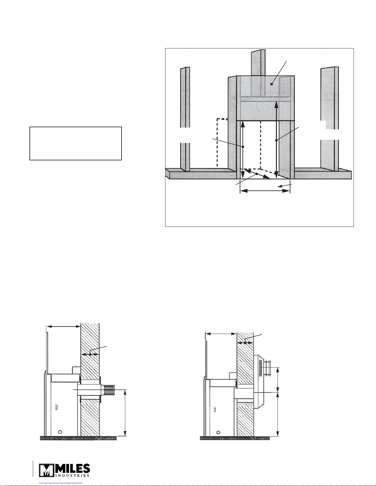
Framing
The framing dimensions are shown in Figure 4.
A non-combustible hearth is not necessary in
•
front of this appliance.
Note that the unit is installed at the framing
•
stage and fi xed to framing using support
angles. See fi gures 26 and 30. Wall fi nish is
then installed over the support angles up to
the black frame on the unit.
Location
Wall Finish
NOTE: If using a 612DKA or
a 613CCB front, refer to the
29-3/4”
to Wall Finish
33-3/4”
to header
kit’s instruction manual for
framing dimensions.
16” min. straight
out or off the top.
Allow for elbow if
rear vent with rise.
Figure 4 Framing
35-1/2”
This is the framing
width. Wall finish
to 32-3/16” wide.
Rear Vent Connection—Flat on Wall
See fi gure 5.
Requires standard vent kit #551DVK only.
The horizontal vent run cannot be extended by the use of any vent accessory pipes.
Rear Vent Connection—Flat on Wall with Snorkel Termination
See fi gure 6.
For use on horizontal installations where the outsides ground level is too close to the standard terminal. Adapter
#817VAK, a pipe length and snorkel termination will be required. See venting accessories list on pages 39–40 for
allowable components.
16”
(41 cm)
min.
14” (36 cm) max.
combustible wall
26” (66 cm) max.
non-combustible wall
23-1/8”
(58.7 cm)
Figure 5 Rear vent—fl at on wall Figure 6 Rear vent—fl at on wall with snorkel
1010
16”
(41 cm)
min.
14” (36 cm) max.
combustible wall
26” (66 cm) max.
non-combustible wall
36” (91.4 mm) or
14” (35.6 mm) rise
(See venting accessories
options at the end of this
manual)
23-1/8”
(58.7 cm)
Location
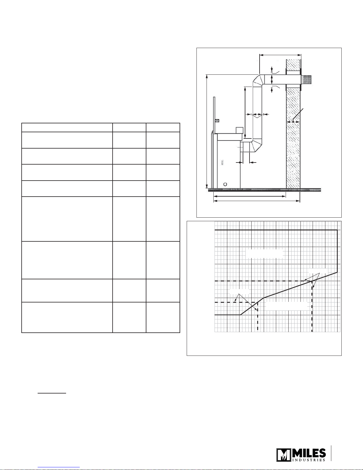
Rear Vent Connection—Vertical Vent Rise with
Horizontal Rear Termination
See fi gure 7.
Can be used with either #551DVK standard vent kit or
another terminal cap and accessories.
Adapter #817VAK, two 90º elbows and pipe lengths will be
required. See venting accessories list on pages 39–40 for
allowable components.
The location requirements are shown in the table and graph
below and figure 7.
Minimum Maximum
A: From fl oor to top of vent duct 4’-3½”
(131 cm)
B: Frame front face to outside
wall
C: Frame front face to inside
wall
D: Vertical pipe run between
elbows
-
2’-5½”
(75 cm)
12”
(30.5 cm)6’(183 cm)
E1+E2: Total horizontal pipe
run including terminal pipe
but excluding adapter and
elbows
-
F: Clearance to combustible
materials above horizontal
pipe run inside building
(Outside wall shields/
1”
(2.5 cm)
thimbles)
G: Clearance to combustible
materials below horizontal
pipe run
1-5⁄16”
(3.3 cm)
H: Clearance to combustible
materials all round vertical
pipe run and at sides of
2”
(5.1 cm)
horizontal pipe run
For installations with a horizontal rear termination, the
combination of horizontal and vertical vent pipes must
be within the allowed area shown in Graph 1. A minimum
vertical pipe run of 12” is necessary.
9’-3½”
(283 cm)
12’-5½”
(380 cm)
-
10’
(305 cm)
with no
elbows in
horizontal
run
-
-
-
E
1
F
G
D
H
A
E
2
C
B
Figure 7 Rear vent—Vertical rise, rear termination
6
Vertical
Rise (Ft)
(D in Fig. 7)
Graph 1
5
4
3
2
1
1
0
ALLOWED VENT PIPE
COMBINATIONS
Example b
FORBIDDEN VENT PIPE
COMBINATIONS
34 56
2
Maximum Horizontal Run (Ft) (E1 + E2 in Fig. 7)
14” (36 cm) max.
combustible wall
Example a
78910
Example a: If a vertical rise of 3’ is required, the horizontal run must not be more than 7’9”.
Example b: If a horizontal run of 3’6” is required, the vertical run must be at least 1’9”.
If the horizontal pipe run is redirected using a further 90° elbow, the maximum total horizontal run allowed is
reduced by 3’ to 7’. Redirection using 45° elbows reduces the maximum total horizontal run by 18” per elbow.
Rear Vent Connection—Vertical Vent Rise with Horizontal Snorkel Termination
For “semi-basement” situations where a snorkel accessory alone does not raise the termination suffi ciently above ground
level. The dimensional requirements in the section above, fi gure 7, and graph 1 apply.
Adapter #817VAK, two 90° vent elbows, pipe lengths and a snorkel termination will be required. A thimble kit may also be
necessary. See venting accessories list on pages 39–40 for allowable components.
1111
Location
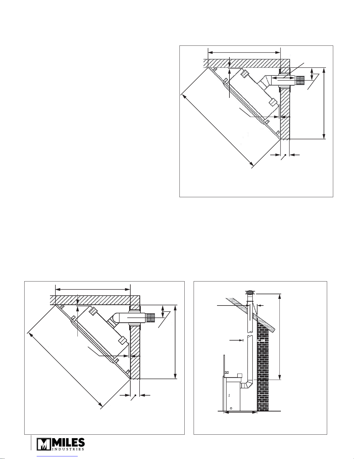
Rear Vent Connection—Corner Location,
Horizontal Vent Run ONLY
45-1/2” (115.5 cm) min.
15” (38 cm)
max. pipe
See fi gure 8.
Can be used with either #551DVK standard vent kit or
another terminal cap and accessories. Adapter #817VAK
and 45° elbow will be required. See venting accessories list
on pages 39–40 for allowable components.
Rear Vent Connection—Corner Location,
Vertical Rise, Horizontal Termination
See fi gure 9.
1-1/2”
64-5/16” (163.3 cm) min.
(38 mm)
min.
clearance
8-1/8”
(20.6 cm)
min.
Can be used with either #551DVK standard vent kit or
another terminal cap and accessories. Adapter #817VAK,
two 90° elbows and pipe lengths will be required. See
venting accessories list on pages 39–40 for allowable
components.
All the vent pipe dimensional limits are as section Rear
Vent Connection—Vertical Vent Rise with Horizontal Rear
9-1/2” (24 cm) max. combustible
or non-combustible wall
Termination.
Rear Vent Connection—Vertical Rise, through
Figure 8 Rear vent connection—Corner location,
horizontal vent run
the Roof Termination
See fi gure 10.
Adapter #817VAK, one 90° vent elbow, pipe lengths, a vertical vent terminal and roof fl ashing will be required. Various
other ceiling or roof items may be necessary depending on the particular installation. See venting accessories list on
pages 39–40 for allowable components.
Note
The distance from the roof to the lowest terminal discharge opening depends on the roof pitch and must be in
1.
accordance with the manufacturer’s instructions supplied with the termination unit.
The venting system for these appliances is considered to be a Special Venting System. The rule in the Natural Gas
2.
and Propane Installation Code CAN/CGA-B149 requiring a minimum vent height of 2’ above any portion of a building
within 10’ does not, therefore, apply.
45-1/2” (115.5 cm) min.
45-1/2” (115.5 cm) min.
1-1/2”
64-5/16” (163.3 cm) min.
(38 mm)
min.
clearance
14” (36 cm) max.
combustible wall
Figure 9 Rear vent connection—Corner location, vertical
rise, horizontal vent run
1212
6-3/8”
(16.2 cm)
min.
5-9/16” (142 mm) min.
from hole
center
to back
wall
45-1/2” (115.5 cm) min.
2” (51 mm) min.
clearance to
combustible
materials
all round
Figure 10 Rear vent connection—Through the roof
28-5/8” (72.7 cm) min.
termination
40’ (12.2 m) max.
10’ (3.05 m) min.
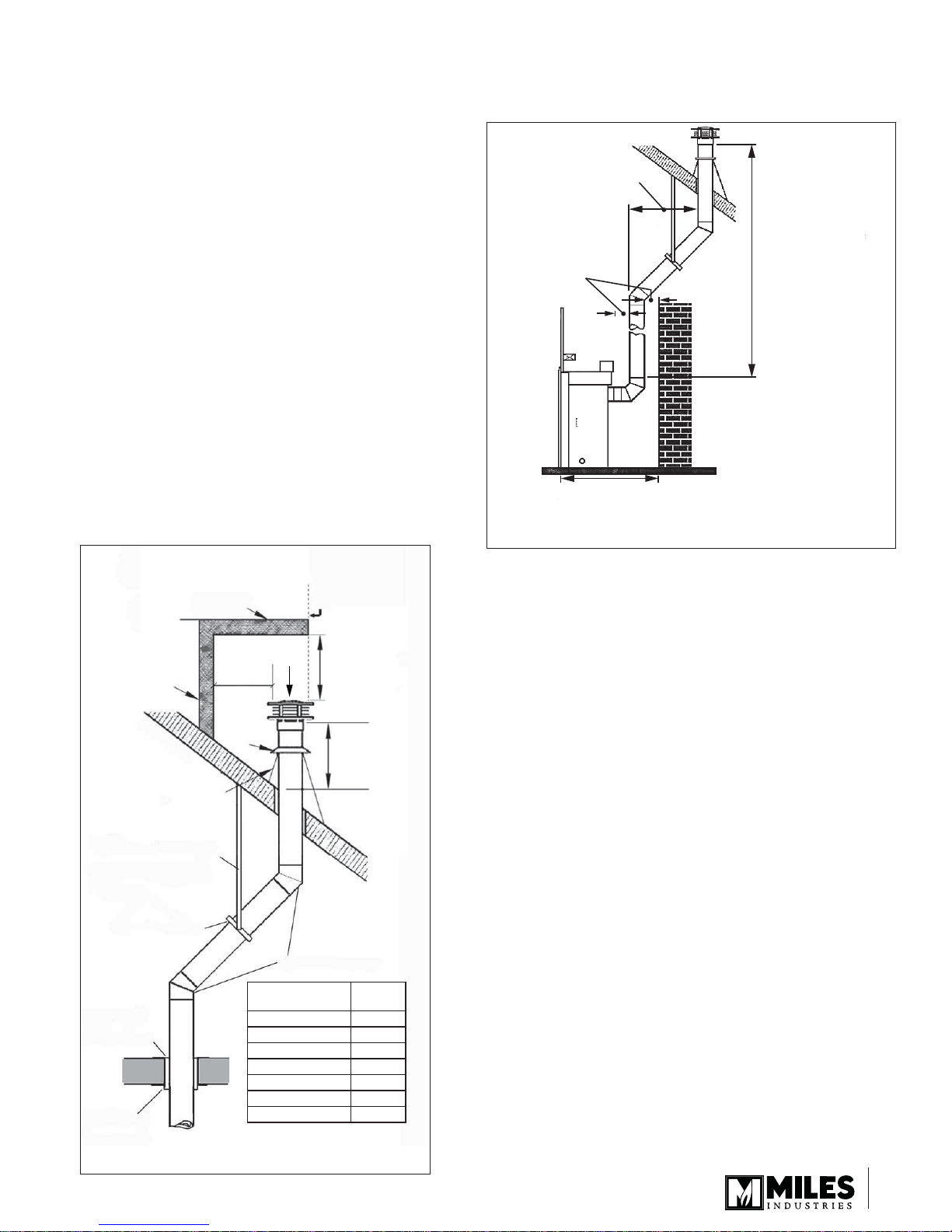
Location
Rear Vent Connection—Vertical Rise with
Offset, through the Roof Termination
See fi gure 11.
For situations where offset is necessary in an attic to avoid
obstructions or allow useful space.
Adapter #817VAK, one 90° vent elbow, two 45° vent elbows,
pipe lengths, a vertical vent terminal and roof fl ashing will
be required. Various other ceiling or roof items may be
necessary depending on the particular installation. See
venting accessories list on pages 39–40 for allowable
components.
Note
The distance from the roof to the lowest terminal
1.
discharge opening depends on the roof pitch and must
be in accordance with the manufacturer’s instructions
supplied with the termination unit.
The venting system for these appliances is considered
2.
to be a Special Venting System. The rule in the Natural
Gas and Propane Installation Code CAN/CGA-B149
requiring a minimum vent height of 2’ above any portion
of a building within 10’ does not, therefore, apply. See
fi gure 11a.
Overhang should
not extend beyond
Horizontal
overhang
vent if within 48” of
termination cap
4’6” (1.37 m) max.
2” (51 mm) min.
clearance to
combustible
materials
all round
28-5/8” (72.7 cm) min.
Figure 11 Rear vent connection—Vertical rise with offset,
through the roof termination
40’ (12.2 m) max.
12’ (3.66 m) min.
Plumber’s tape
fixed to wall strap
Wall strap
Ceiling
firestop
Ceiling
support
Vertical
wall
Roof
flashing
Termination
Min.
18”
Storm
collar
Roof Pitch Minimum
Flat to 7/12 1’
Over 7/12 to 8/12 1.5’
Over 8/12 to 9/12 2’
Over 9/12 to 10/12 2.5’
Over 10/12 to 11/12 3.25’
Over 11/12 to 12/12 4’
Over 12/12 to 14/12 5’
Min. 24”
cap
(unvented soffit)
Min. 36”
(vented soffit)
‘H’
Offset elbows
‘H’ (feet)
Figure 11a
1313
 Loading...