

Valor 534AN, 534AP Installation And Owner's Manual
Direct Vent Gas Fireplace Heaters
Model 534AN (Natural Gas)
Model 534AP (Propane)
Installation and Owner’s Manual
Please read this manual before installin g and operating this heater
This manual should remain with the homeowner
WARNING: If the information in these
instructions is not followed exactly, a
fire or explosion may result causing
property damage, personal injury or
loss of life.
- Do not store or use gasoline or other
flammable vapors and liquids in the vicinity
of this or any other appliance.
-WHAT TO DO IF YOU SMELL GAS
• Do not try to light any appliance.
• Do not touch any electrical switch: do not
use any phone in your building.
• Immediately call your gas supplier from a
neighbor’s phone. Follow the gas
supplier’s instructions.
• If you cannot reach your gas supplier, call
the fire department.
- Installation and service must be performed
by a qualified installer, service agency or the
gas supplier.
This appliance may be installed in an
aftermarket permanently located,
manufactured (mobile) home, where not
prohibited by local codes.
This appliance is only for use with the type of
gas indicated on the rating plate. This
appliance is not convertible for use with
other gases, unless a certified kit is used.
This appliance is a domestic room heating
appliance. It must not be used for any other
purpose such as drying clothes etc.
This appliance is suitable for installation in a
bedroom or bed sitting room.

CONTENTS
1. SAFETY INFORMATION........................................................................................................................................................................3
2. OPTIONS................................................................................................................................................................................. ....................4
2.1. Appliance styles..................................................................................................................................................................................4
2.2. Optional outer trims ....................................................... ...................................................................................................................4
2.3. Additional optional features .............................................................................................................................................................4
2.4. Venting options........................................................................................................... ........................................................................4
3. GENERAL................................................................................................................................................ ...................................................6
3.1. Approvals & codes.............................................................................................................................................................................6
3.2. Ratings........................................................................................................................................................................................ .........6
3.3. Wall Thickness ............................................................................................... ..... ...... ........................................................................6
4. LOCATION.............................................................................. ................................................................ ...................................................7
4.1. Framing...............................................................................................................................................................................................7
4.2. Rear Vent Connection. Flat on Wall............................................................................................................. ...................................7
4.3. Rear Vent Connection. Flat on Wall with Snorkel Termination..................................................................................................7
4.4. Rear Vent Connection, Vertical Vent Rise with Horizontal Rear Termination.........................................................................8
4.5. Rear Vent Connection, Vertical Vent Rise with Horizontal Snorkel Termination....................................................................8
4.6. Corner Location, Rear Vent Connection, Horizontal Vent Run Only ........................................................................................9
4.7. Corner Location, Rear Vent Connection, Vertical Rise, Horizontal Termination ....................................................................9
4.8. Rear Vent Connection, Vertical Rise, Through the Roof Termination.......................................................................................9
4.9. Rear Vent Connection,Vertical Rise with Offset, Through the Roof Termination..................................................................10
4.10. Top Vent Connection, Horizontal Rear Termination..................................................................................................................11
4.11. Top Vent Connection, Horizontal side termination.....................................................................................................................12
4.12. Top Vent Connection, Horizontal Side or Rear Snorkel Termination......................................................................................12
4.13. Top Vent Connection, Corner Location, Horizontal Termination, 45° Pipe Run....................................................................12
4.14. Top Vent Connection, Through the Roof Termination*...........................................................................................................13
4.15. Top Vent Connection, Offset and Through the Roof Termination*............................................................................ ............13
4.16. Vent Location ....................................................... ........... ...... ..... ..... ........... ..... ..... ........... .................................................................14
5. SUPPLY GAS............................................................................................................................................................................................15
6. PACK CONTENTS ................................................................................................................................. .................................................15
7. APPLIANCE PREPARATION................................................................................................................... ............................................17
7.1. Window Removal................................................................................................................. ............................................................17
7.2. Ignition Spark Check.......................................................................................................................................................................17
7.3. Flame Control Motor Check...........................................................................................................................................................17
7.4. Rear Vent Outlet positioning..........................................................................................................................................................18
7.5. # 817VAK Pipe Adapter Fitting.....................................................................................................................................................18
7.6. Top Heat Shield & Stand-off Fitting..............................................................................................................................................19
7.7. Support Angle Fitting......................................................................................................................................................................19
7.8. Attaching Air Restrictors............................................................................... ............................................................... ..................20
7.9. Attaching Rear Ceramic Support ........................................................................................................................................... .......21
7.10. Attaching to the Framing ............................................................... ............................................................... ..................................21
8. INSTALLATIONS WITH HORIZONTAL TERMINATION – INSTALLING TO WALL..........................................................22
8.1. Flat On Wall Installations With Valor #551DVK Terminal...................................................................... .................................22
8.2. Wall Opening.............................................................. ........... ..... ..... ..... ........... ..... ...... ..... ..... ............................................................23
8.3. Valor Terminal #551DVK - Preparing Wall Plates .............................................................. .......................................................23
8.4. Dura-vent Terminals – Installing to wall ............................................................................................................... .......................23
9. INSTALLATIONS WITH THROUGH THE ROOF VERTICAL TERMINATION ................................................... ...... .......... ..24
10. SWITCH FITTING..................................................................................................................................................................................25
10.1. For wall switch as only active switch ............................................................................ ..... ......... ...................................................25
10.2. For active remote control with or without active wall switch.....................................................................................................25
11. GAS SUPPLY INSTALLATION & AERATION SETTING.............................................................................................................26
11.1. Gas Supply Installation...................................................................................................................................................................26
11.2. Aeration Setting Check............................................................................................................. .......................................................26
12. CERAMIC FUEL BED INSTALLATION ...........................................................................................................................................27
12.1. Ceramic Walls Installation .............................................................................................................................................................27
12.2. Ceramic Logs Installation...............................................................................................................................................................27
13. WINDOW REFITTING & CHECKING..............................................................................................................................................28
14. OPERATION CHECKS..........................................................................................................................................................................28
15. FRONT INSTALLATION......................................................................................................................................................................29
15.1. Additional Optional 3 or 4 Sided Trims........................................................................................................................................29
15.2. #601SFB Standard Metal Front......................................................................................................... ............................................29
15.3. #602CFB Cast Iron Front ...............................................................................................................................................................29
2
1. SAFETY INFORMATION
WARNING: Do not operate the appliance with the
glass front removed, cracked or broken. Replacement
of the glass should be done by a licensed or qualified
service person.
(The whole window unit may be temporarily removed
by the owner for cleaning the interior of the firebox,
etc.)
Only the authorized Valor replacement window unit
listed in the repair parts booklet must be fitted - never
use substitutes.
If the glass is damaged, search inside and adjacent to
the appliance for any glass fragments.
Due to high temperatures, the appliance should be
located out of traffic and away from furniture and
draperies.
Children and adults should be alerted to the hazards
of high surface temperatures and should stay away to
avoid burns or clothing ignition.
Young children should be carefully supervised when
they are in the same room as the applian ce.
Clothing or other flammable material should not be
placed on or near the appliance.
This appliance must be installed and repaired by a
qualified service person. The appliance should be
inspected before use and at least annually by a
professional service person. More frequent cleaning
may be required due to excessive lint from carpeting,
bedding material, etc. It is imperative that control
compartments, burners and circulating air
passageways of the appliance are kept clean.
When operating your new fireplace for the first time, some vapors may be released due to the burning of curing compounds
used in the manufacture of the appliance. They may cause a slight odor and could cause the flames to be the full height of the
fire box, or even slig htly higher, for the fi rst few hours of operation. It is also possible that these vap ors could set off any
smoke detection alarms in the immediate vicinity. These vapors are quite normal on new appliances and are totally harmless
but you may wish to open windows into the room to reduce the vapor/odor build up. After a few hours use the vapors will
have disappeared and the flames will be at their normal height.
During the first hour of use, the ceramic firebox walls may go a smoky color. This is not soot. It is a temporary effect lasting
only while the ceramic material becomes stabilized. The walls will revert to their initial color after your fire has been used for
one or two hours.
Keep curtains, clothing, furnit u re and othe r
flammable materials a safe distance from all parts of
the appliance and its vent system.
Keep the appliance area well clear and free from
combustible materials, gasoline and other flammable
vapors and liquids.
Never attempt to burn paper or any other mate rial in
the appliance.
The venting terminal must not be recessed into a wall
or siding.
The vent terminal on the outside wall m ust be kept
free from obstructions. No objects sh ould be placed
within 2 feet (60cm) of the vent terminal. The terminal
is hot during operation and requires a guard if it is
accessible to any person. An approved Valor guard is
available from your dealer.
During extreme weather conditions ensure that the
vent outlet is free from ice and snow before attempting
to light.
Do not use this appliance if any part has been under
water. Immediately call a qualified service technician
to inspect the appliance and to replace any part of the
control system and any gas control which has been
under water.
NOTE
3

2. OPTIONS
Heater engine unit #534EAN is use d with all natural gas
installations.
Heater engine unit #534EAP is used with all propane
installations.
2.1. Appliance styles
Standard metal front. Black – Kit #601SFB
Cast iron front. Black – Kit #602CFB.
One of the above kits must be used with each
installation.
2.2. Optional outer trims
3 sided Black – Kit #603FSK
3 sided Champagne – Kit# 604FSK
4 sided Black – Kit #605FSK
4 sided Champagne – Kit# 606FSK
2.3. Additi onal optional features
Remote control unit Hand operated control for
flame & heat adjustment. It
may be fitted before the
fireplace is installed or
retrofitted at a later date -
Kit #553RCK.
Circulating fan Having variable speed and
temperature control, it is
designed to boost the natural
convection process through the
appliance. It may be fitted
before the fireplace is installed
or retrofitted at a later date –
Kit #555CFK.
Wall switch extension Optional 10ft. long wire kit that
enables the switch to be sited
on a wall further away from the
appliance than the standard
switch. The standard switch has
4ft. of wire.
Kit #609WEK
Natural Gas For conversion from propane to
Conversion kit natural gas – Kit #607NGK.
Intended primarily for post
installation conversion in areas
where natural gas was not
available at the time of initial
installation.
2.4. Venting options
2.4.1. Direct vent installations
One or more of the accessories listed below must be used
for each installation. See the “Location” section of this
manual.
Kit#
551DVK
817VAK
984
942
945B
990B
908B
907B
906B
904B
903B
902B
911B
981
982
991
940
941
963
943
943S
953
988
835TG
Valor horizontal terminal kit provides up
to 26” (66cm) horizontal run. Complete
with wall plates and clearance shield
approved for a maximum 14” (36cm)
combustible wall.
Adapter for Dura-vent pipes
Dura-vent DV GS horizontal square
terminal c a p
Dura-vent DV GS wall thimble kit
45° Dura-vent DV GS elbow
90° Dura-vent DV GS elbow
6” Dura-vent DV GS pipe length
9” Dura-vent DV GS pipe length
12” Dura-vent DV GS pipe length
24” Dura-vent DV GS pipe length
36” Dura-vent DV GS pipe length
48” Dura-vent DV GS pipe length
Adjustable 11”-14
pipe length
Dura-vent DV GS snorkel termination
unit – 36” rise
Dura-vent DV GS snorkel termination
unit – 14” rise
Dura-vent DV GS high wind vertical
termination cap
Dura-vent DV GS round ceiling support
Dura-vent DV GS cathedral ceiling
support box
Dura-vent DV GS ceiling firestop
Dura-vent DV GS adjustable roof
flashing. Roof pitch 0/12 – 6/12
Dura-vent DV GS steep roof flashing.
Roof pitch 7/12 – 12/12
Dura-vent DV GS storm collar
Dura-vent DV GS wall strap
Terminal Guard
5
/8” Dura-vent DV GS
4
gure 3 #602C
optional t
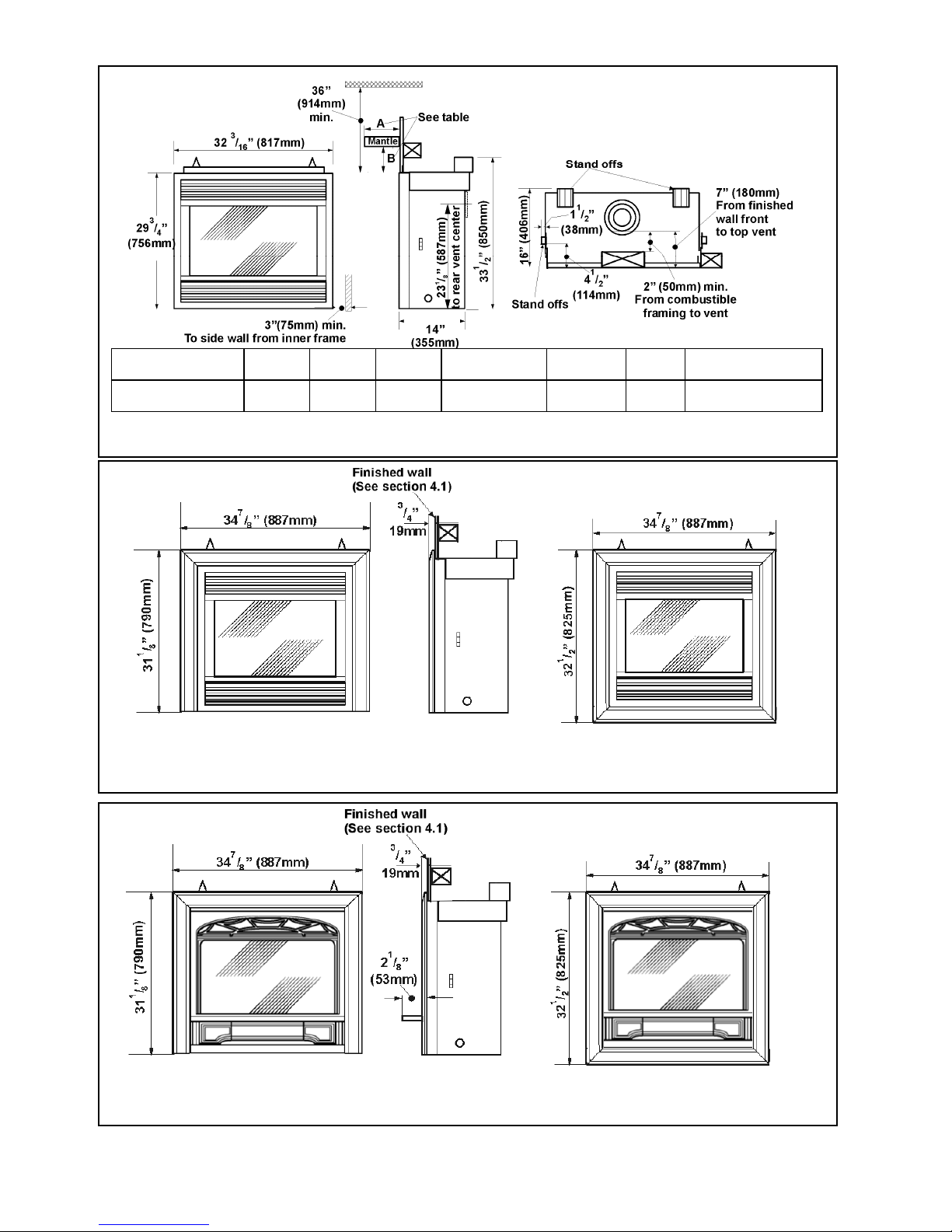
Mantle depth “A” 1”
Mantle clearance “B” 7”
(25mm)
(178mm)
2”
(51mm)
8”
(203mm)
3”
(76mm)
9”
(229mm)
(102mm- 127mm)
4”-5”
10”
(254mm)
6”
(152mm)
11”
(279mm)
7”
(178mm)
12”
(305mm)
8”–12”
(203mm-305mm) max.
14”
(356mm)
Figure 1 Major dimensions & clearances without opt iona l tr ims (Shown with # 601S F B Fron t)
3 sided trims 4 sided trims
Figure 2 #601SFB Front with optional trims
3 sided trims 4 sided trims
Fi
FB Front with
rims
5
3. GENERAL
3.1. Approvals & codes
These appliances are certified by C.S.A. for use in Canada and the US A. These ap plia nce s are for instal la tio n direc tly vent i ng
through an outside wall or through the roof.
Model 534AN is for use with natural gas.
Model 534AP is for use with propane. It can be converted for use with natural gas with kit #607NGK.
These appliances comply with CGA P.4.1, Testing metho d for measur ing a nn ual firep lace e fficiencies.
The installation must conform with loca l codes or, in the absence of local codes with the National Fuel Gas Code, ANSI
Z223.1or the Canadian installation code CAN/CGA-149. Only qualified licensed or trained personnel should install these
appliances.
These appliances, when installed, must be el ectrically grounded in accordance with loc al codes or, in the absence of local
codes, with the National Electrical Code, ANSI/NFPA 70 or the Canadian Electrical Code, CSA C22.1.
3.2. Ratings
Model
Gas Natural Propane
Altitude (Ft) 0-4500 1
Input Max. (Btu/h) 24,000 24,000
Input Min (Btu/h) 6,500 13,000
Manifold pressure (in.w.c.) 3.8-4.2 9.3-9.7
Min. Supply pressure (in. w.c.) 5.0 11.0
Max. Supply pressure (in. w.c.) 10.5 14.0
1
Tested to CAN/CGA - 2.17 Gas fired appliances for use at high altitudes. In the USA, installations may require deration over
2000ft - Check local codes.
3.3. Wall Thickness
The vent system (when horizontally termina ted) is approved to pass through a combustible wall up to 14” (36cm) thick.
A non-combustible wall can be any th ickness up to the maximum horizontal run of vent pipe allowed for the particular
installation – See section 4.
534AN 534AP
6
4. LOCATION
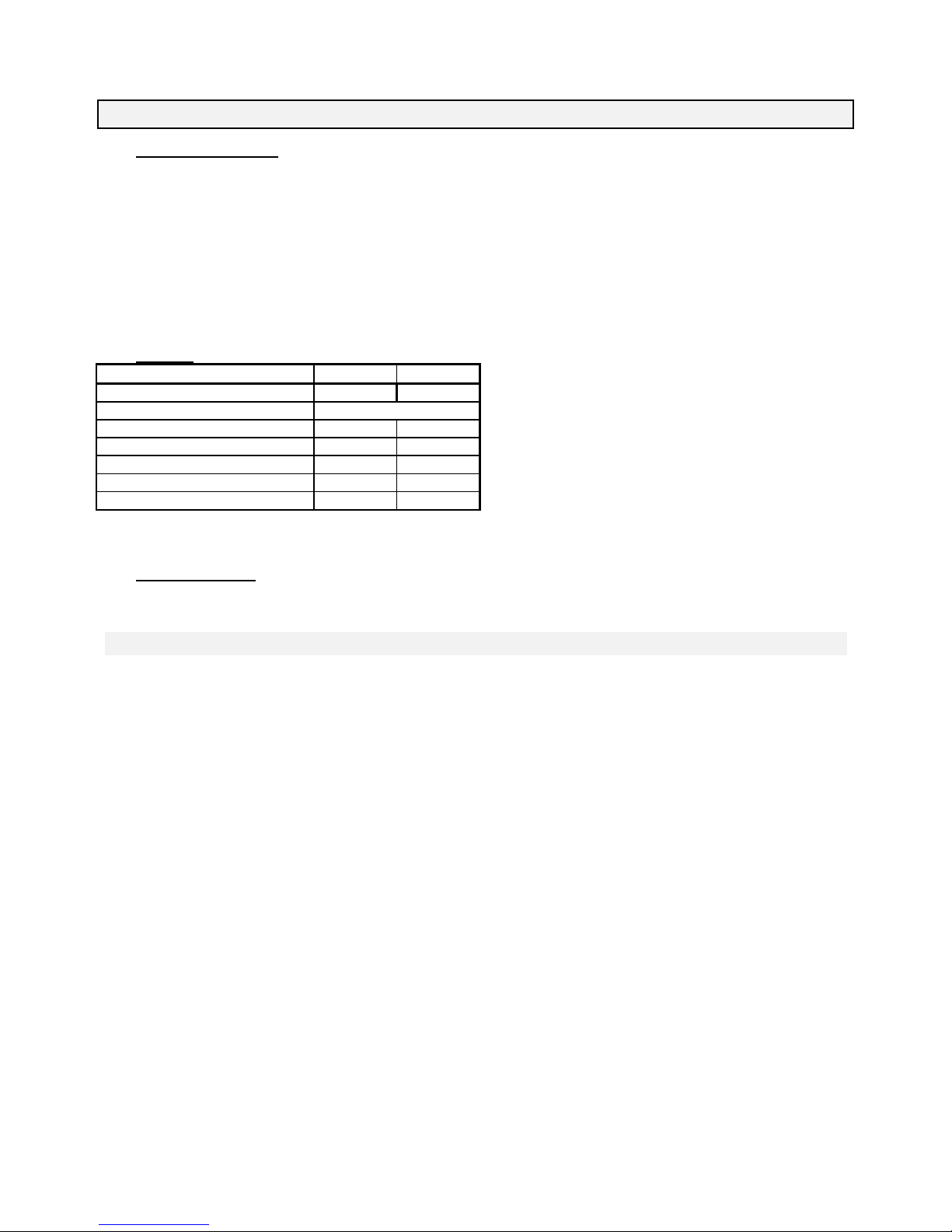
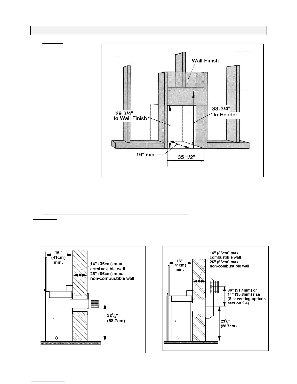
4.1. Framing
The framing dimensions are shown
in figure 4.
• A non-combustible hearth is
not necessary in front of this
appliance.
• All combustible materials must
be outside the dimensions
shown in figure 4.
4.2. Rear Vent Connection. Flat on Wall
See figure 5.
Requires standard vent kit #551DVK only.
The horizontal vent run can not be extended by the use of any vent accessory pipes.
4.3. Rear Vent Connection. Flat on Wall with Snorkel Termination
See figure 6.
For use on horizontal installations where the outsides ground level is too close to the standard terminal. Adapter #817VAK, a
Dura-vent pipe length and snorkel termination #981 or #982 will be require d (Se e vent options sect i on of this manua l).
Figure 4 Framing
Figure 5 Rear vent. Flat on wall
7
Figure 6 Rear vent. Flat on wall with S norkel
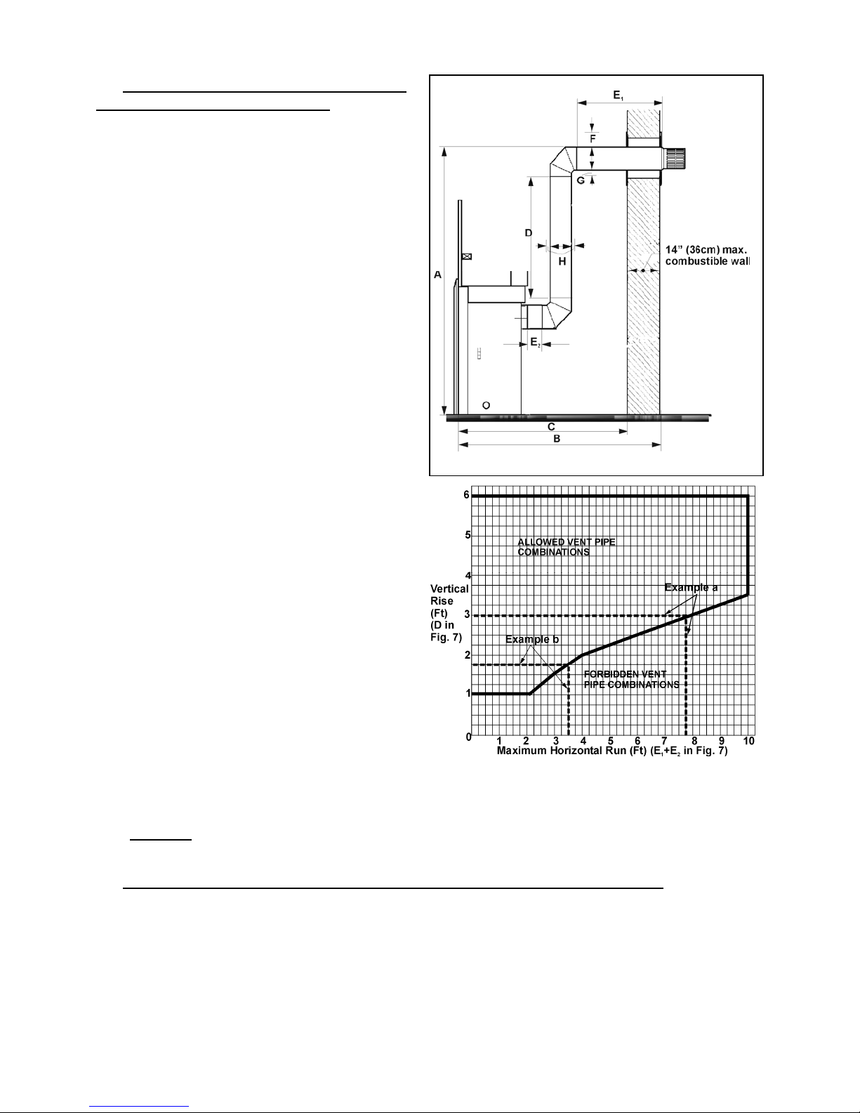
4.4. Rear Vent Connection, Vertical Vent Rise
with Horizontal Rear Termination
See figure 7.
Can be used with either #551DV K standard vent kit or #984
Dura-vent terminal cap and accessories.
Adapter #817VAK, two 90° vent elbows #990B and Duravent pipe lengths will be required.
(See venting options section of this manual).
The location requirements are shown in the table and graph
below and figure 7.
A: From floor to top of
vent duct
B: Frame front face to
outside wall
C: Frame front face to
inside wall
D: Vertical pipe run
between elbows
E
: Total horizontal
1+E2
pipe run including
terminal pipe but
excluding adapter and
elbows
F: Clearance to
combustible materials
Minimum Maximum
4ft 3½”
(131cm)
9ft 3½”
(283cm)
- 12ft 5½”
(380cm)
2ft 5½”
-
(75cm)
12”
(30.5cm)
6ft
(183cm)
- 10ft
(305cm)
with no
elbows in
horizontal
run
1”
-
(12.7cm)
Figure 7 Rear vent, vertical rise, rear termination
above horizontal pipe run
inside building (Outside
wall shields/thimbles)
G: Clearance to
combustible materials
5
/16”
1
(3.3cm)
-
below horizontal pipe run
H: Clearance to
combustible materials all
2”
(5.1cm)
-
round vertical pipe run
and at sides of horizontal
pipe run
For installations with a horizontal rear termination, the
combination of horizontal and ve rtical vent pipes must be
within the allowed area shown in Graph 1. A minimum
vertical pipe run of 12” is necessary.
Example a: If a vertical rise of 3ft is required, the
horizontal run must not be more than 7ft 9”.
Graph 1
Example b: If a horizontal run of 3ft 6” is required, the vertical run must be at least 1ft 9”.
If the horizontal
pipe run is redirected using a further 90ºelbow, the ma ximu m total horizontal run allowed is reduced
by 3ft. to 7ft. Redirection using 45º elb ows reduces the maximum total horiz on tal run by 18” per elbow.
4.5. Rear Vent Connection, Vertical Vent Rise with Horizontal Snorkel Termination
For “semi-basement” situations where a snorkel accessory alone does not raise the termination sufficiently above ground
level. The dimensional requirements in section 4.4, figure 7 and graph 1 apply.
Adapter #817VAK, two 90º vent elbows #990B, Dura-vent pipe lengths and a Dura-vent snorkel termination will be required.
#942 Dura-vent thimble kit may also be necessary. (See venting options section of this manua l)
8
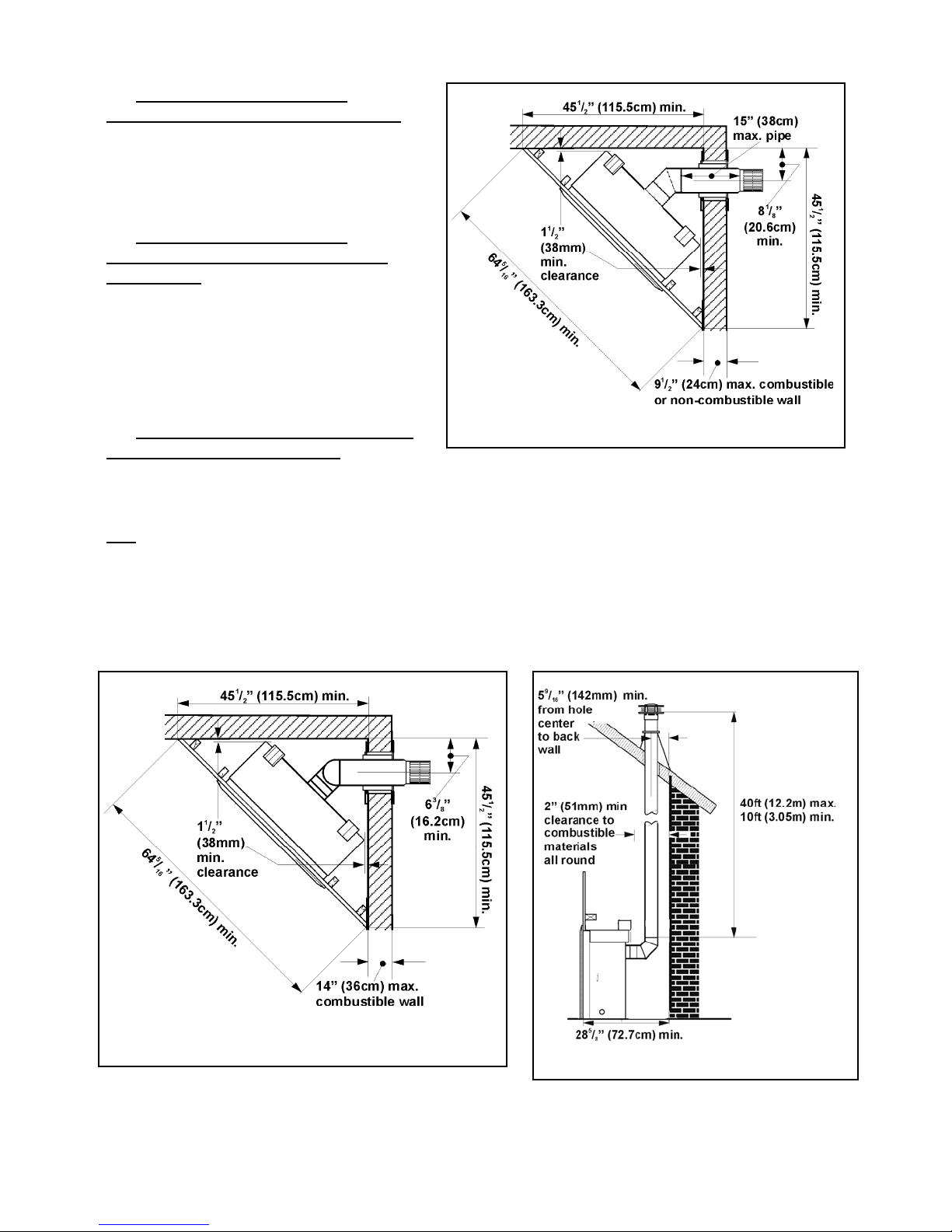
4.6. Corner Location, Rear Vent
Connection, Horizontal Vent Run Only
See figure 8.
Can be used with either #551DV K standard vent kit or
#984 Dura-vent terminal cap and accessories. Adapter
#817VAK and 45º Dura-vent elb ow # 945B will be
required. (See venting options section of t his manual.)
4.7. Corner Location, Rear Vent
Connection, Vertical Rise, Horizontal
Termination
See figure 9.
Can be used with either #551DV K standard vent kit or
#984 Dura-vent terminal cap and accessories. Adapter
#817VAK, two 90º Dura-vent elbows #990B and Duravent pipe lengths will be required. (See venting options
section of this manual).
All the vent pipe dimensional limits are as section 4.4.
4.8. Rear Vent Connection, Vertical Rise,
Figure 8 Corner location, rear vent connection, horizonta l vent run
Through the Roof Termination
See figure 10.
Adapter #817VAK, one 90º vent elbow #990B, Dura-vent pipe lengths, a vertical ven t termina l and roof flashi ng will be
required. Various other ceiling or roof items may be necessary depending on the particular installation (See venting options
section of this manual).
Note
1. The distance from the roof to the lowest terminal discharge opening de pends on the roof pitch and must be in accordance
with the Dura-vent instructions supplied with the termination unit.
2. The venting system for these appliances is considered to be a Special Venting System. The rule in the Installation Code
CAN/CGA–B149 requiring a minimum vent height of 2ft above any portion of a building within 10ft does not,
therefore, apply.
Figure 9 Corner location, rear vent connection, vertical rise,
horizontal vent run
Figure 10 Rear vent connection, through the roof
termination
9
 Loading...