

Valor 530XAN, 530XAP, 530XCN, 530XCP Installation And Owner's Manual
g
Model 530XAN/XAP
Model 530XCN/XCP
Direct Vent Gas Fireplace Heater
(With Logs or Coals)
Installation and Owner’s Manual
INSTALLER: Leave this manual with the appliance.
CONSUMER: Retain this manual for future reference.
PLEASE READ THIS MANUAL BEFORE
INSTALLING AND OPERATING THIS HEATER.
WARNING: If the information in these
instructions is not followed exactly, a
fire or explosion may result causing
property damage, personal injury or
loss of life.
- Do not store or use gasoline or other
flammable vapors and liquids in the vicinity
of this or any other appliance.
-WHAT TO DO IF YOU SMELL GAS
• Do not try to light any appliance.
• Do not touch any electrical switch: do not
use any phone in your building.
• Immediately call your gas supplier from a
neighbor’s phone. Follow the gas supplier’s
instructions.
• If you cannot reach your gas supplier, call
the fire department.
- Installation and service must be performed
by a qualified installer, service agency or
the gas supplier.
Manufactured by
This appliance may be installed in an
aftermarket permanently located,
manufactured (mobile) home, where not
prohibited by local codes.
This appliance is only for use with the type of
gas indicated on the rating plate. This
appliance is not convertible for use with
other gases, unless a certified kit is used.
This appliance is a domestic room-heating
appliance. It must not be used for any other
purpose such as drying clothes etc.
B-Vent Installations
If this appliance is intended to be installed with a
B-Vent instead of direct vent, use this manual in
conjunction with the manual supplied with the BVent adapter kit #552BVK.
This appliance is suitable for installation in a
bedroom or bed sitting room.
Massachusetts: The piping and final gas
connection must be performed by a licensed
plumber or gas fitter in the State of
Massachusetts. Also, see Carbon Monoxide
detector requirements under “Safety and
Warnin
Information” on page 4.
MILES INDUSTRIES LTD.
British Columbia, Canada
4000305-10

CONTENTS
1. SAFETY INFORMATION.......................................................................................................... .............3
2. OPTIONS....................................................................................................................................................6
3. GENERAL........................................................... .......................................................................................9
4. LOCATION – PRESIDENT FS.............................................................................................................10
5. LOCATION – ZERO CLEARANCE....................................................................................................17
6. RECESSED INSERT APPLICATIONS...............................................................................................25
7.
DIRECT VENT TERMINAL LOCATION..........................................................................................26
8. HEATER PACK CONTENTS…………………………………………………………………..........27
9. HEATER PREPARTION.......................................................................................................................28
10. INSTALLING HORIZONTAL TERMINATION...............................................................................32
11. INSTALLING ROOF TERMINATION...............................................................................................33
12. REMOTE CONTROL INSTALLATION ............................................................................................35
13. GAS SUPPLY INSTALLATION........................................... ................................................................36
14. AERATION SETTING CHECK ................................. ..........................................................................37
15. CERAMIC FUEL BED INSTALLATION...........................................................................................37
16. WINDOW REFITTING & CHECKING..............................................................................................40
17. OPERATION CHECKS .........................................................................................................................40
18. INSTALLATION OF FRONTS AND COMPONENTS.....................................................................41
19.
20. LIGHTING INSTRUCTIONS.............................................................................................. ................49
21. APPROVED VENT SUPPLIERS..........................................................................................................50
22. WARRANTY............................................................................................................................................52
2.1. Appliance styles
2.2. Additional optional features
2.3. LP Gas
2.4. Venting options
3.1. Approvals & codes
3.2. Ratings
3.3. Wall Thickness
3.4 Supply Gas
3.5 Controls
3.6 Electrical
4.1. Wall & Floor Fixing
4.2. Venting configurations
5.1. Framing General
5.2. Finishing General
5.3. President 536/ Bolero 541 Fronts
5.4 Windsor Arch 539 Front
5.5 Z.C Venting Configurations
9.1. Detach the window
9.2. Check ignition spark
9.3. Burner Module Removal
9.4. Conversion to Top Outlet
9.5. Rear Outlet Preparation
9.6. DuraVent Co-Linear
9.7. Valor 556 CLA Co-Linear Adapter
9.8. Air Restrictor
15.1. Ceramic Walls Installation
15.2. Ceramic Log Installation
15.3. Ceramic Coals Installation
18.1 President 531 Free Standing Fron t
18.2 President 536/Bolero 541 Z.C Fronts
18.3 Windsor Arch 539/549 Fronts
OWNERS INFORMATION...................................................................................................................46
19.1. Operating Your Fire
19.2 Operating remote control
19.3. Cleaning
19.4. Checks
19.5. Servicing
19.6. General servicing
2 of 50
1.0 SAFETY INFORMATION
WARNING: Do not operate the appliance with the
glass front removed, cracked or broken. Replacement
of the glass should be done by a licensed or qualified
service person.
(The whole window unit may be temporarily removed
by the owner for cleaning the interior of the firebox,
etc.)
Only the authorized Valor replacement window unit
listed in the repair parts booklet must be fitted - never
use substitutes.
If the glass is damaged search inside and adjacent to
the appliance for any glass fragments.
Due to high temperatures, the appliance should be
located out of traffic and away from furniture and
draperies.
Children and adults should be alerted to the hazards
of high surface temperatures and should stay away to
avoid burns or clothing ignition.
Young children should be carefully supervised when
they are in the same room as the applian ce.
Clothing or other flammable material should not be
placed on or near the appliance.
This appliance must be installed and repaired by a
qualified service person. The appliance should be
inspected before use and at least annually by a
professional service person. More frequent cleaning
may be required due to excessive lint from carpeting,
bedding material, etc. It is imperative that control
compartments; burners and circulating air
passageways of the appliance are kept clean.
When operating your new fireplace for the first time, some vapors may be released due to the burning of curing compounds
used in the manufacture of the appliance. They may cause a slight odor and could cause the flames to be the full height of the
firebox, or even slightly highe r, for the first few hours of operation. It is also possible that these vapors coul d set off any
smoke detection alarms in the immediate vicinity. These vapors are quite normal on new appliances. We recommend opening
a window to vent the room. After a few hours use the vapors will have disappeared and the flames will be at their normal
height.
During the first hour of use the ceramic firebox walls may go a smoky color. This is not soot. It is a temporary effect lasting
only while the ceramic material becomes stabilized. The walls will revert to their initial color after your fire has been used for
one or two hours.
Keep curtains, clothing, furnit u re and othe r
flammable materials a safe distance from all parts of
the appliance and its vent system.
Keep the appliance area well clear and free from
combustible materials, gasoline and other flammable
vapors and liquids.
Never attempt to burn paper or any other mate rial in
the appliance.
The venting terminal must not be recessed into a wall
or siding.
The vent terminal on the outside wall m ust be kept
free from obstructions. No objects should be placed
within 2 feet (60cm) of the vent terminal. The terminal
is hot during operation and requires a guard if it is
accessible to any person. An approved Valor guard is
available from your dealer.
During extreme weather conditions ensure that the
vent outlet is free from ice and snow before attempting
to light.
Do not use this appliance if any part has been under
water. Immediately call a qualified service technician
to inspect the appliance and to replace any part of the
control system and any gas control, which has been
under water.
Should you encounter an operational problem,
call your dealer immediately.
Do not try to repair the unit as you may cause an
injury or damage the fireplace.
NOTE
3 of 50

State of California. Proposition 65 Warning.
products of combustion of such fuels, contain chemicals known to the State of California to cause cancer, birth defects
and other reproductive harm. California Health & Safety Code Sec. 25 249.6.
State of Massachusetts Carbon Monoxide Detector/Vent Terminal Signage Requirements
For all side wall horizontally vented gas fueled equipment installed in every dwelling, building or structure used in
whole or in part for residential purposes, including those owned or operated by the Commonwealth and where the side
wall exhaust vent termination is less than seven (7) feet above finished grade in the area of the venting, including but
not limited to decks and porches, the following requirements shall be satisfied:
1. INSTALLATION OF CARBON MONOXIDE DETECTORS. At the time of installation of the side wall horizontal
vented gas fueled equipmen t, the installing plumber or gasfitter shall observe that a hard wired carbon monoxide
detector with an alarm and battery back-up is installed on the floor level where the gas equipment is to be installed. In
addition, the installing plumber or gasfitter shall observe that a battery operated or hard wired carbon monoxide
detector with an alarm is installed on each additional level of the dwelling, building or structure served by the side wall
horizontal vented gas fueled equipment. It shall be the responsibility of the property owner to secure the services of
qualified licensed professionals for th e installation of hard wired carbon monoxide detectors.
a. In the event that the side wall horizontally vented gas fueled equipment is installed in a crawl space or an attic, the
hard wired carbon monoxide detector with alarm and battery back- up may be installed on the next adjacent floor level.
b. In the event that the requirements of this subdivision can not be met at the time of completion of installation, the
owner shall have a period of thirty (30) days to comply with the above requirements; provided, however, that during
said thirty (30) day period, a battery operated carbon monoxide detector with an alarm shall be installed.
2. APPROVED CARBON MONOXIDE DETECTORS. Each carbon monoxide detector as required in accordance
with the above provisions shall comply with NFPA 720 and be ANSI/UL 2034 listed and IAS certified.
3. SIGNAGE. A metal or plastic identification plate shall be permanently mounted to the exterior of the building at a
minimum height of eight (8) feet above grade directly in line with the exhaust vent terminal for the horizontally vented
gas fueled heating appliance or equipment. The sign shall read, in prin t size no less than one-half (1/2) inch in size,
“GAS VENT DIRECTLY BELOW. KEEP CLEAR OF ALL OBSTRUCTIONS”.
4. INSPECTION. The state or local gas inspector of the side wall horizontally vented gas fueled equipment shall not
approve the installation unless, upon inspection, the inspector observes carbon monoxide detectors and signage
installed in accordance with the provisions of 248 CMR 5.08(2)(a)1 through 4.
Fuels used in gas, wood-burning or oil fired appliances, and the
(b) EXEMPTIONS: The following equipment is exempt from 248 CMR 5.08(2)(a)1 through 4:
1. The equipment listed in Chapter 10 entitled “Equipment Not Required To Be Vented” in the most current edition of
NFPA 54 as adopted by the Board; and
2. Product Approved side wall horizontally vented gas fueled equipment ins t alled in a room or structure separate from
the dwelling, building or structure used in whole or in part for residential purposes.
(c) MANUFACTURER REQUIREMENTS - GAS EQUIPMENT VENTING SYSTEM PROVIDED. When the
manufacturer of Product Approved side wall horizontally vented gas equipment provides a venting system design or
venting system components with the equipment, the instructions provided by the manufacturer for installation of the
equipment and the venting system shall include:
4 of 50

1. Detailed instructions for the installation of the venting system design or the venting system components; and
2. A complete parts list for the venting system design or venting system.
(d) MANUFACTURER REQUIREMENTS - GAS EQUIPMENT VENTING SYSTEM NOT PROVIDED. When the
manufacturer of a Product Approved side wall horizontally vented gas fueled equipment does not provide the parts for
venting the flue gases, but identifies “special venting systems”, the following requirements shall be satisfied by the
manufacturer:
1. The referenced “special venting system” instructions shall be included with the appliance or equipment installation
instructions; and
2. The “special venting systems” shall be P r oduct Approved by the Board, and the instructions for that system shall
include a parts list and detailed installation instructions.
(e) A copy of all installation instructions for all Product Approved side wall horizontally vented gas fueled equipment,
all venting instructions, all parts lists for venting instructions, and/or all venting design instructions shall remain with
the appliance or equipment at the completion of the installation.
5 of 50

2.0 OPTIONS
Heater engine unit # 530 X is available in either natural
gas or LPG and comes equipped with either a simulated
log or coal fuel bed in either fuel. The 5 30X engine unit is
supplied standard with a rear vent D.V outlet and may be
converted to a top outlet D.V with no extra parts required.
The parts required to make the engine suitable for zero
clearance are supplied with the various front trims (except
549 front)
2.1 Appliance styles
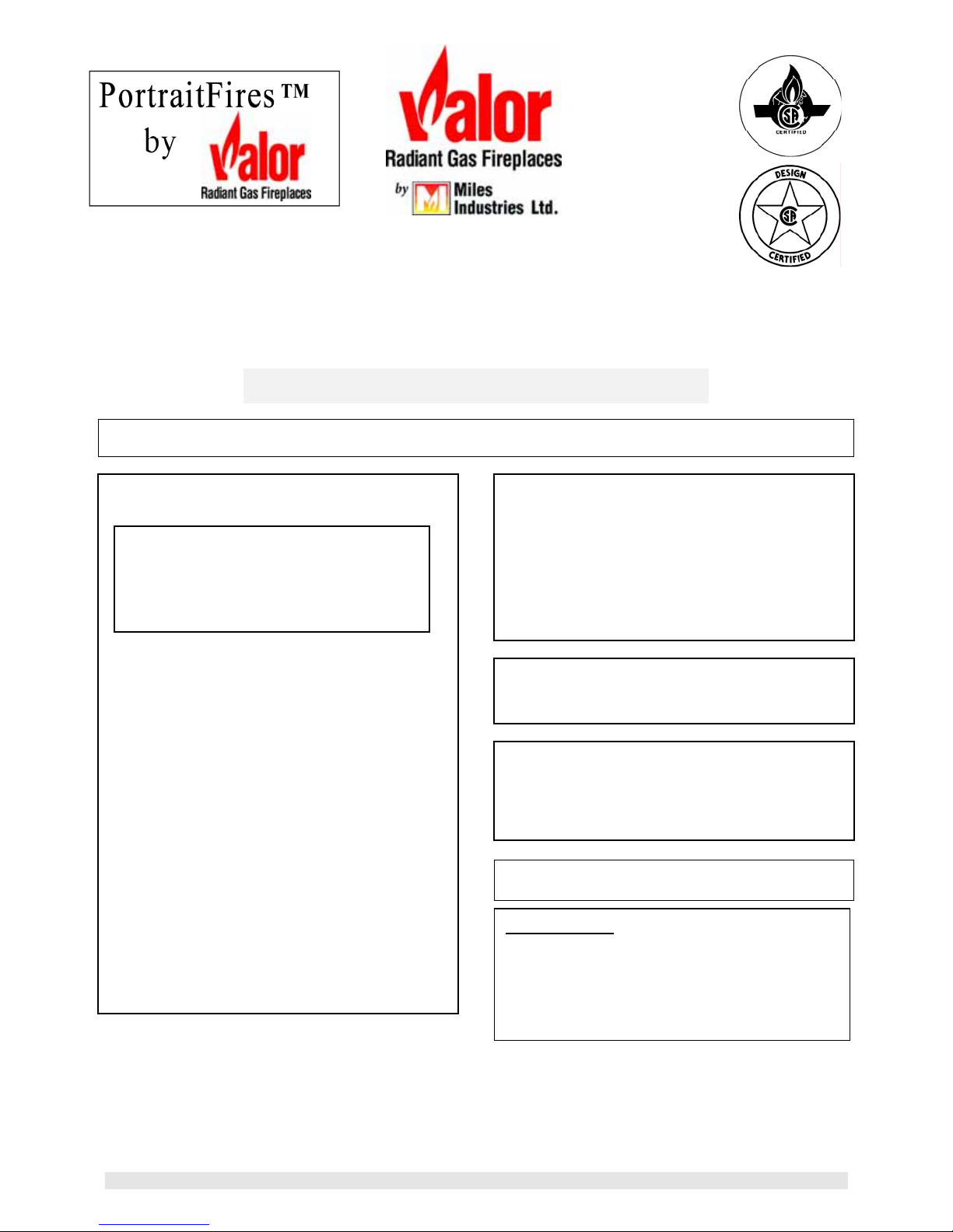
President FS Free standing cast stove.(See fig. 1),
President 536 For recessed application, either zero
clearance or insert . (See figure 2)
Windsor Arch
539/549 Arched Cast Iron Front for recessed
application, either zero clearance (see
fig 3) or insert (see fig 4 ). (549
version is insert only )
Bolero 541 Contemporary cast iron front for
recessed application, either zero
clearance or insert(see fig 5)
One of the above kits must be used with each
installation.
2.2 Additional optional features
Circulating fan Having variable speed and
temperature control, it is
designed to boost the natural
convection process through the
appliance. It may be fitted
before the fireplace is installed
or retrofitted at a later date –
Kit #555CFK.
3336 CP
Closure Plate 33” high x 36” wide black
closure plate with black
aluminum extrusion edge. To
cover openings for insert
applications.
2.3 LP Gas
LPG Conversion kit Burner & injector kit for
conversion from natural gas to
propane – Kit #554LPK.
2.4 Venting options
2.4.1 Direct vent installations (solid piping)
A list of all approved venting accessories is shown on
pages 48 and 49 of this manual.
2.4.2 Direct Vent Co-Linear Installations for
Free Standing or Recessed Installations
(flexible piping)
Converts the appliance outlet collars to accept two 3” dia.
Flex liners for installation into existing solid fuel burning
fireplaces and chimneys. Requires 556 CLA adapter and
923 GK termination kit along w ith either a 980 or 991
termination cap.( 923GCL may be use d in lieu of 556
CLA adapter)
2.4.3 B-vent installations – For President
Free Standing only
Kit #552BVX converts this appliance from a direct vent
fireplace heater to a gravity vent fireplace heater for use
with a 4” “B” type vent. A full installation and operating
manual is supplied with the kit.
6 of 50
Figure 1. Model 531 President Free Standing – Dimensions
Figure 2. Model 536 Recessed Presiden t – Dimensions
Figure 3. Model 539 Windsor Arch. with Backplate - Dimensions
7 of 50
Mantle depth “A” Min. Clearance“B”
Up to 12” 4”
Above 12” up to 18” 8”
More than 18” 8”+extra 1” for every
Mantle leg
projection “D”
Up to 8” 1”
More than 8” 6”
Mantle depth “A” Min. Clearance“B”
Up to 7” 4”
Above 7” up to 8” 5”
Above 8” up to 9” 7”
Above 9” up to10” 8”
Above 10” up to 12” 9”
More than 12” 9”+extra 1” for every
Mantle leg
projection “D”
Up to 8” 0”
More than 8” 6”
1” depth above 18”
Min clearance from
appliance side “E”
1” depth above 12”
Min clearance from
appliance side “E”
Fig 4. 549 Windsor Arch without ba ckplate.
Note – this option is intended for insert appl ications only
for zero clearance applications. Most recessed 530 insert applications will also require a 556 CLA co-linear adapter
and does not include the stand-offs and insulation pads required
Fig 5. - 541 Recessed Bolero Dimensions
8 of 50
3.0 GENERAL
3.1 Approvals & codes
This appliance is certified by International Approval Services for use in Canada and the USA.
The appliance complies with CGA P.4.1, Testing method for measur ing a nnu al fireplace efficiencies.
The installation must conform with loca l codes or, in the absence of local codes with the National Fuel Gas Code, ANSI
Z223.1or the Canadian installation code CAN/CGA-149. Only qualified licensed or trained personnel should install the
appliance.
The appliance, when installed, must be electrically grounded in accordance with local codes or, in the absence of local codes,
with the National Electrical Code, ANSI/NFPA 70 or the Canadian Electrical Code, CSA C22. 1.
3.2 Ratings
Altitude (Ft) 0-4500 *
Input Max. (Btu/h) 20,500 19,000
Input Min (Btu/h) 6,000 11,600
Manifold pressure (in.w.c.) 3.5 – 3.9 10.3 – 10.7
Min. Supply pressure (in. w.c.) 5.0 11.0
Max. Supply pressure (in. w.c.) 10.5 14.0
*Tested to CAN/CGA - 2.17 Gas fired appli ances for use at high altitudes. In the USA installations may require dera tion over
2000ft - Check local codes.
3.3 Wall Thickness
The appliance vent is suitable for penetrati ng a combustible wall up to 14” ( 36cm) thick.
A non-combustible wall can be any th ickness up to the maximum horizontal run of vent pipe allowed for the particular
installation – See sections 4 and 5.
3.4 Supply Gas
Heater engine 530XAN /XCN is used on Natural gas installations.
Heater engine 530XAP/XCP is used on Propane installations .
The supply pressure must be between the limits shown in section 3.2 above.
The supply connection is
The opening for the gas supply line is at the rear left corner of the appliance.
3
/8’’NPT.
3.5 Controls
The unit is supplied standard with a battery operated, hand held remote control and receiver which has the ability to adjust the
gas input of the unit between the pilot setting and the maximum input .Th e pilo t ligh t must be m anua lly lit at the va lve and
may be left on or turned off with each use. The rem ote control provides full thermostatic or manual operation with the option
of programming thermostat function between certain times of the day. Manual operation of the valve is also possib le should
the batteries or remote control fail.
3.6 Electrical
The unit does not require an electrical power source unless fitted with an opt ional circulating fan.
Nat. Gas LPG
9 of 50

4.0 LOCATION – PRESIDENT FREE STANDING
4.1 Wall & Floor Fixing
The President FS can be installed against a wall or in the
room away from walls. The appliance is designed to be fixed
to the floor. The appliance can additionally or alternatively be
fixed to a rear wall. The fixing positions are shown in figure
6. The appliance is approved for installation directly on wood
flooring. If the appliance is installed directly on carpeting,
vinyl tile or other combustible material other than wood
flooring, it must be installed on a me tal or wood panel
extending the full width and depth of the appliance.
4.2 Venting configurations
4.2.1 Flat on wall
Requires Valor vent kit #551DVK or other pipe length with
adapter #817VAK and terminal cap.
The location requirements are shown in figure 7.
The horizontal vent run cannot be extended beyond the
dimensions shown in figure 5 by the use of any vent accessory
pipes.
4.2.2 Flat on wall with snorkel termination
(Fig.8)
For use on horizontal vent installations where the outsi de
ground level is too close to the standard terminal. Adapter
#817VAK, a pipe length and snorkel termination will be
required (See vent options section of this manual).
Figure 6 President FS fixing holes
Figure 7
Figure 8
10 of 50
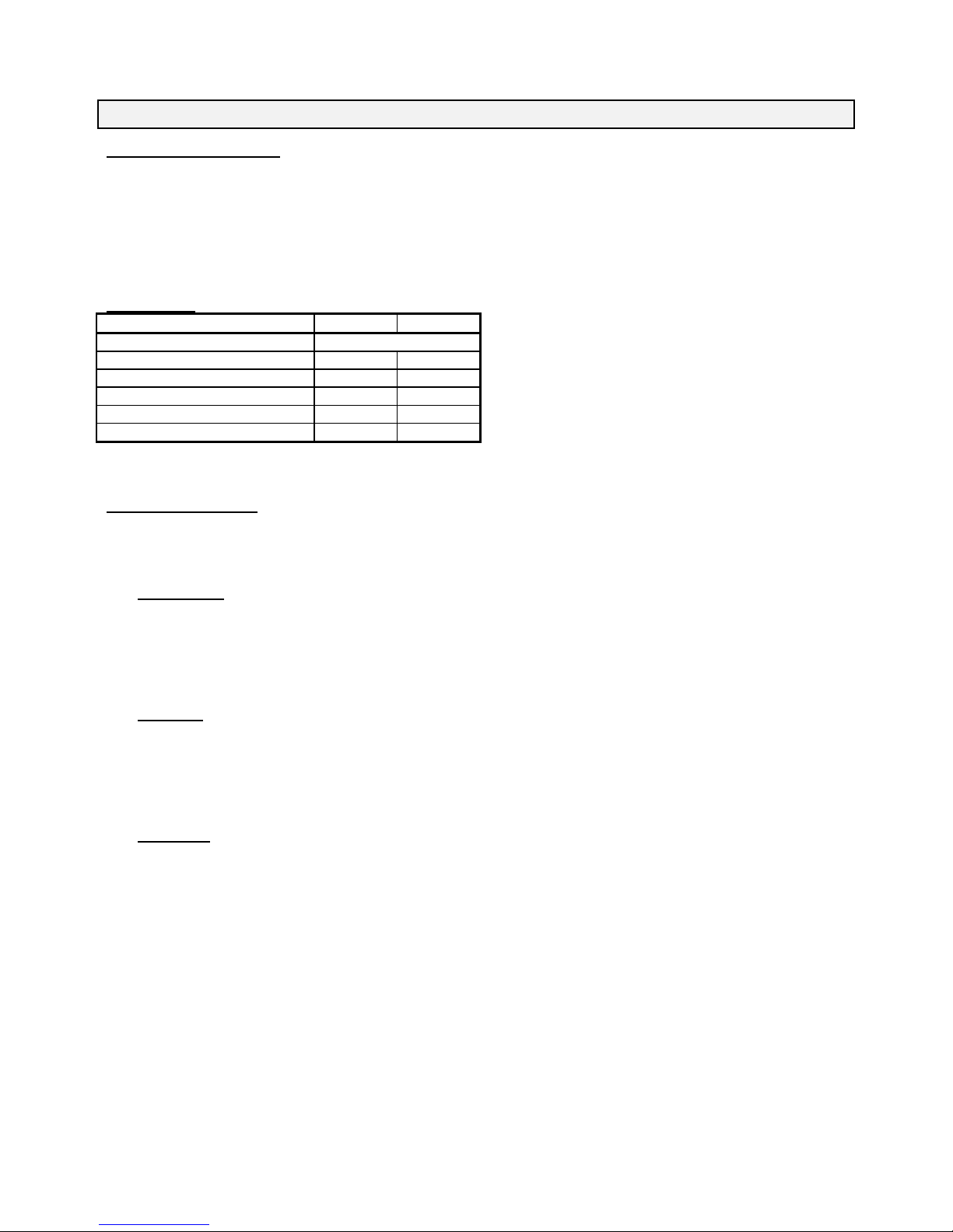
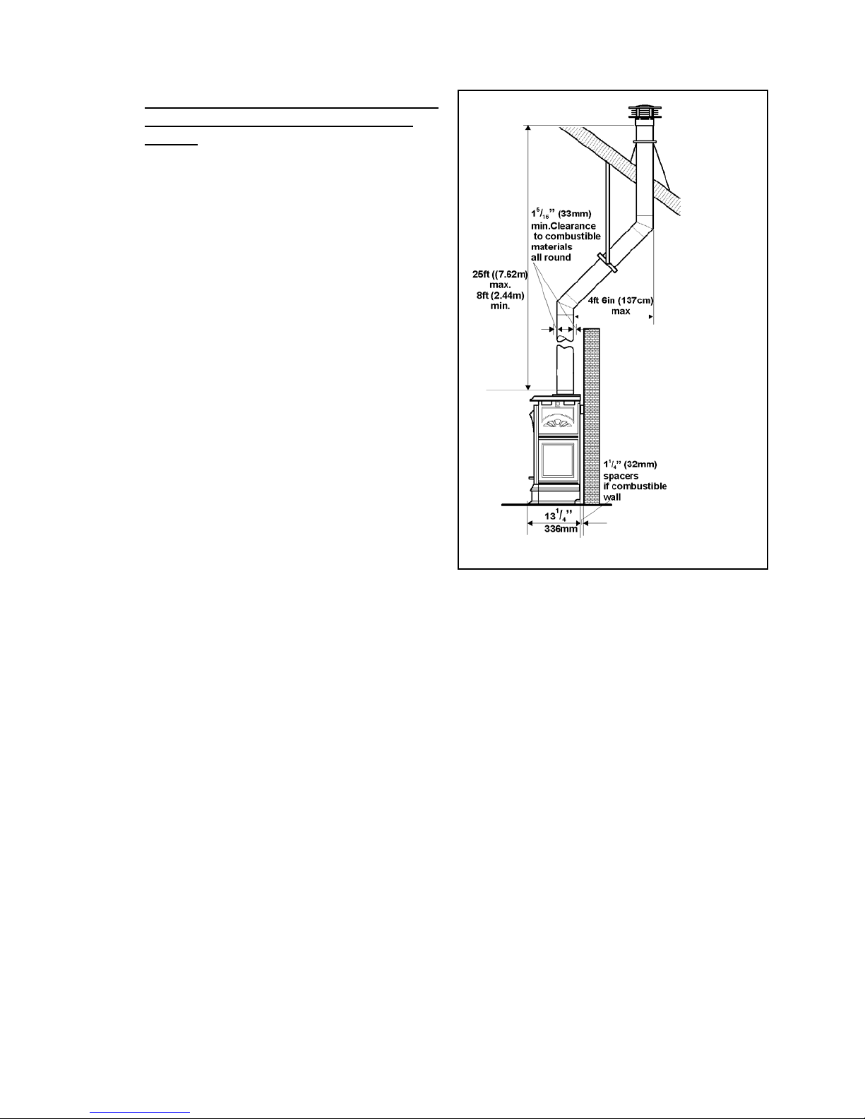
4.2.3 Rear vent connection, vertical vent rise with
horizontal termination (Fig. 9)
Can be used with either #551DV K standard vent kit or another
terminal cap and accessories.
Adapter #817VAK, two 90° vent elbows and pipe lengths will be
required.
(See venting options section of this manual).
No more than two 90°elbows must be used.
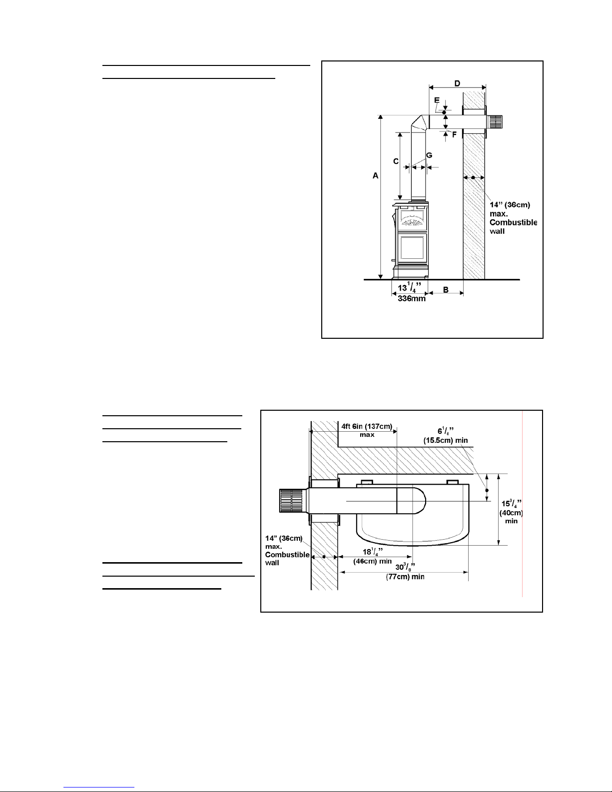
A: From floor to top of
vent duct
B: Back of appliance
to outside wall
C: Back of appliance
to inside wall
Minimum Maximum
3ft 7in
(109cm)
10ft 7in
(323cm)
- 5ft 5in
(165cm)
-
14
1
/8in
(36cm)
D: Vertical pipe run 12in (30cm) 8ft (244cm)
E: Horizontal pipe run
(Total before and after
elbows)
F: Clearance to
combustible materials
above horizontal pipe
run
G: Clearance to
combustible materials
- 4ft 6in
(137cm)
5
2
/8in
-
(6.7cm)
5
1
/16in
-
(3.3cm)
Figure 9
below horizontal pipe
run
H: Clearance to
combustible materials
5
1
/16in
(3.3cm)
-
all round vertical pipe
run and at sides of
horizontal pipe run
4.2.4 Rear vent connection, vertical vent rise with horizontal snorkel termination
For “semi-basement” situations where vertical vent rise does not raise horizontal termination sufficiently above ground level.
The dimensional requirements in section 4.2.3 and figure 9 apply.
Adapter #817VAK, two 90° vent elbows, pipe lengths and a snorkel terminati on will be required.
A wall thimble kit may also be necessary.
(See venting options section of this manual).
No more than two 90°elbows must be used.
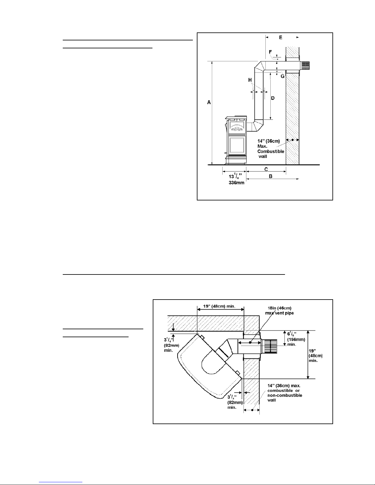
4.2.5 Corner location, horizontal
vent run only (Fig. 10)
Can be used with either #551DVK standard
vent kit or another terminal cap and
accessories.
Adapter #817VAK and 45° elbow will be
required.
(See venting options section of this manual).
Be aware of the limited maximum vent pipe
length and wall depth for this type of
installation – See figure 10.
Figure 10
11 of 50
4.2.6 Corner location, rear vent
connection, vertical rise,
horizontal termination
(Figs 9 & 11)
Can be used with either #551DVK standard vent kit
or another terminal cap and accessories.
Adapter #817VAK, two 90° vent elbows and pipe
lengths will be required.
(See venting options section of this manual).
No more than two 90°elbows must be used.
All vertical dimensional limits are as section 4.2.3.
4.2.7 Rear vent connection, vertical
vent rise with through the roof
termination (Fig.12)
Adapter #817VAK, one 90° vent elbow, pipe
lengths, a vertical vent terminal and roof flashing
will be required. Various other ceiling or roof items
may be necessary depending on the particular
installation (See venting options section of this
manual).
4.2.8 Rear vent connection, vertical
vent rise with offset and through
the roof termination (Fig.13)
For situations where offset is necessary in
an attic to avoid obstructions or allow useful
space.
Adapter #817VAK, one 90° vent elbow,
two 45° vent elbows, wall straps, a vertical
vent terminal, roof flashing and pipe lengths
will be required. Various other ceiling or
roof items may be necessary depending on
the particular installation ( See venting
options section of this manual).
Figure 11
Figure 12
Figure 13
12 of 50
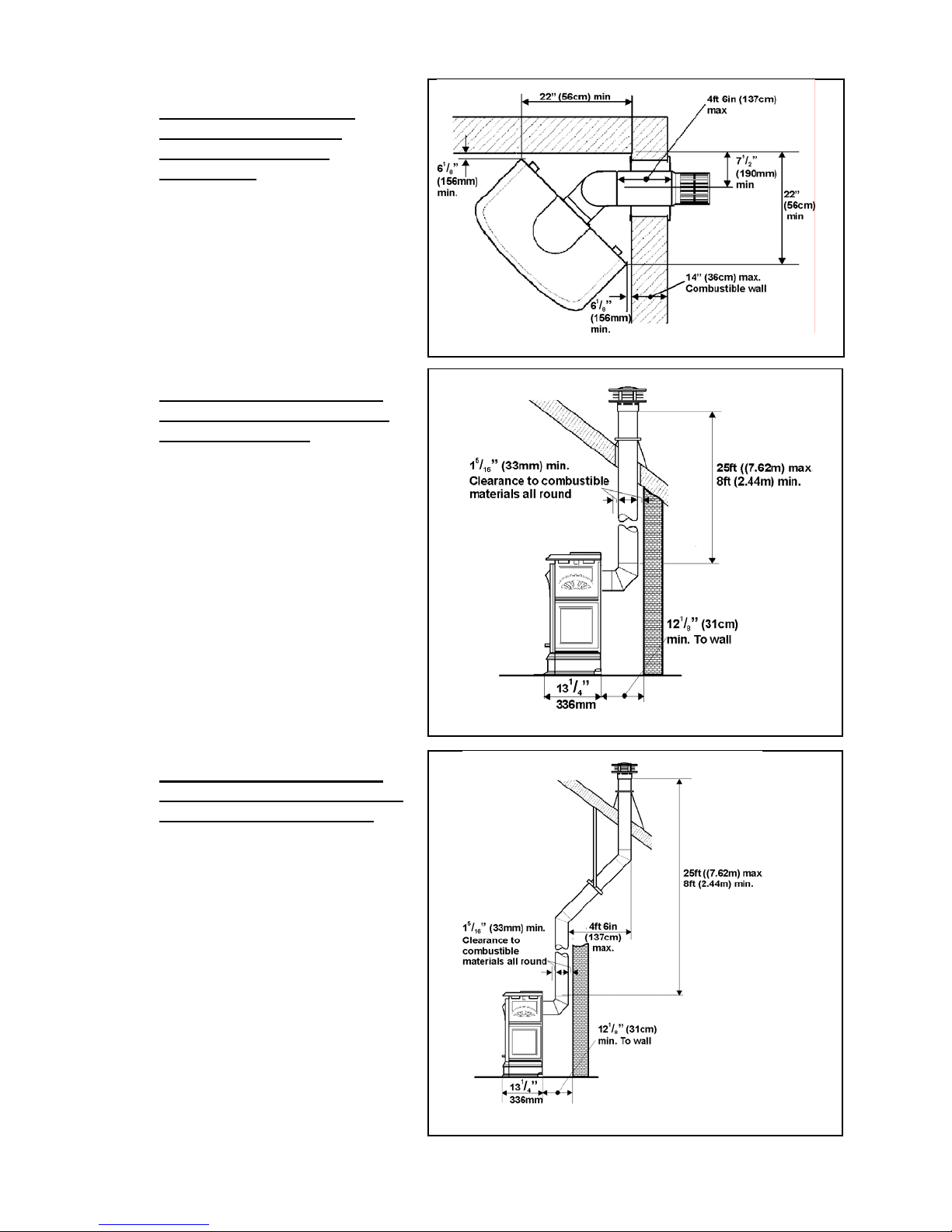
4.2.9 Rear vent connection, installed
to fireplace chimney with colinear liners (Fig.14)
Only for use when retrofitting a non-combustible
fireplace and chimney.
The appliance must not be connected to a chimney
flue serving a separate solid-fuel burning
appliance.
Requires 556 CLA Co-Axial to Co-Linear
appliance adapter, two lengths of 3” dia. flexible
chimney liner, co-linear termination kit and
flashing and either high wind vertical vent
terminal cap or a low profile vertical termination
cap .(See vent options section of this manua l).
4.2.10 Rear Vent Conversion to B-Vent
using 552 BVK Adapter
Free Standing Only ( Fig 15)
Used to field convert heater from direct ven t to 4”
dia. gravity vent on free standing units only . A
full installation and operating manual is supplied
with the kit.
Figure 14
552 BVK Adapter
Fig 15.
13 of 50
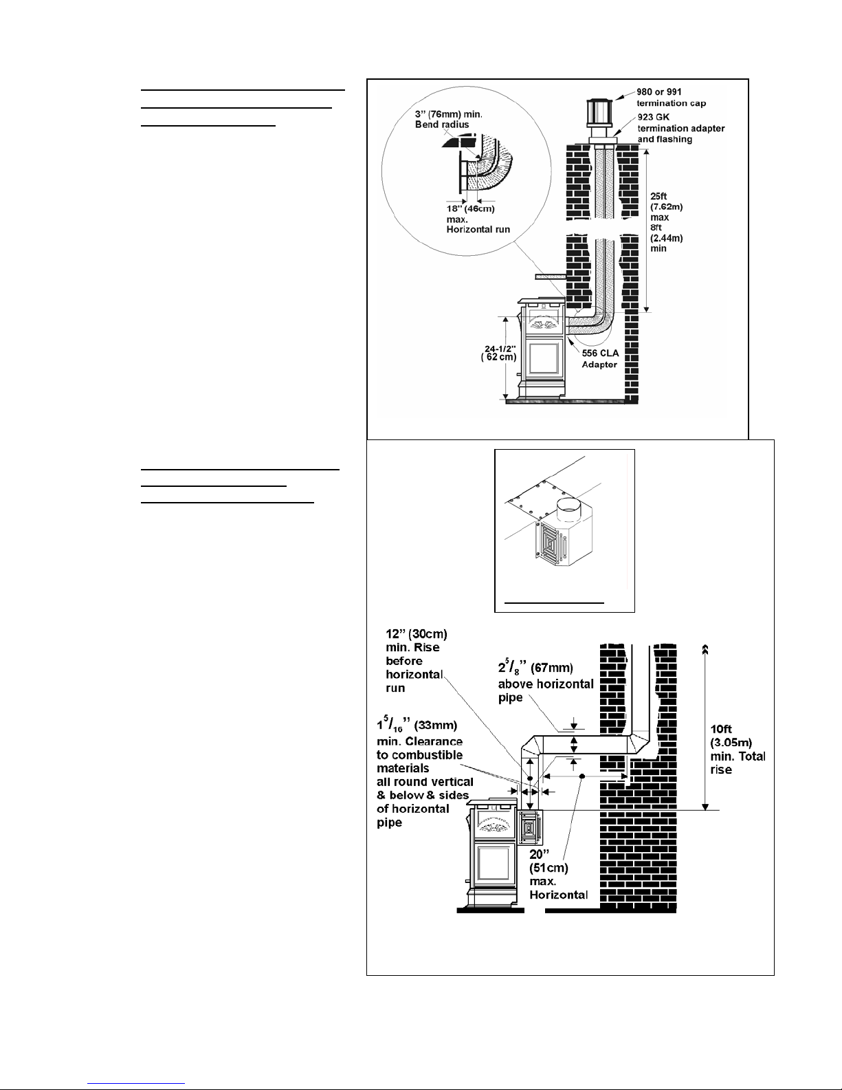
4.2.11 Top vent connection, vertical vent rise with
horizontal rear termination (Fig.16)
Can be used with either #551DV K standard vent kit or another
terminal cap and accessories.
Adapter #817VAK, one 90° vent elbow and pipe lengths will be
required.
(See venting options section of this manual).
No more than two 90°elbows must be used.
A: From floor to top of
vent duct
B: Back of appliance
to inside wall
C: Vertical pipe run 9in
Minimum Maximum
4ft
(122cm)
1
3
/4 in
11ft
(335cm)
-
(79mm)
8ft
(23cm)
(244cm)
D: Horizontal pipe run - 4ft 6in
(137cm)
-
E: Clearance to
combustible materials
5
2
/8in
(6.7cm)
above horizontal pipe
run
F: Clearance to
combustible materials
5
1
/16in
(3.3cm)
-
below horizontal pipe
run
G: Clearance to
combustible materials
5
1
/16in
(3.3cm)
-
all round vertical pipe
run and at sides of
horizontal pipe run
4.2.12 Top vent connection, vertical
vent rise with horizontal side
termination (Figs.16 &17)
Can be used with either #551DVK standard vent
kit or another terminal cap and accessories.
Adapter #817VAK, one 90° vent elbow and pipe
lengths will be required.
(See venting options section of this manual).
No more than two 90°elbows must be used.
All vertical dimension, pipe run and clearance
limits are as section 4.2.11.
4.2.13 Top vent connection, vertical
vent rise with horizontal side or
rear snorkel termination
The dimensional requirements in sec tions 4.2.11
and 4.2.12 apply.
Adapter #817VAK, one 90° vent elbow, pipe
lengths and a snorkel termination will be required.
A thimble kit may also be necessary.
(See venting section of this manual).
Figure 17
Figure 16
14 of 50

4.2.14 Top vent connection,
corner location, vertical
rise, horizontal
termination, 45° pipe bend
(Figs 16 & 18)
Can be used with either #551DVK standard
vent kit or another terminal cap and
accessories.
Adapter #817VAK, one 90° elbow, one 45°
elbow and pipe lengths will be requir ed.
(See venting section of this manual).
All vertical dimensions and clearance limits
are as section 4.2.11.
Figure 18
4.2.15 Top vent connection,
corner location, vertical
rise, straight horizontal
termination (Figs 16 & 19)
Can be used with either #551DVK standard
vent kit or another terminal cap and
accessories.
Adapter #817VAK, one 90° elbow and pipe
lengths will be required. (See venting
section of this manual).
All vertical dimensions and clearance limits
are as section 4.2.11.
.
Figure 19
4.2.16 Top vent connection, vertical vent rise,
through the roof termination (Fig. 20)
Adapter #817VAK, pipe lengths, a vertical vent terminal and
roof flashing will be required. Various other ceiling or roof
items may be necessary depending on the particular installation
(See venting options section of this manual).
Figure 20
15 of 50
4.2.17 Top vent connection, vertical vent rise with
offset and through the roof termination
(Fig.21)
For situations where offset is necessary in an attic to avoid
obstructions or allow useful space.
Adapter #817VAK, two 45° vent elbows, wall straps, a vertical
vent terminal, roof flashing and pipe lengths will be required.
Various other ceiling or roof items ma y be necessary depending
on the particular installation (see ve nting options section of this
manual).
Figure 21
16 of 50
 Loading...