

#536CXB
President ZC Cast Front
CSA approved for use only with
Valor 530
Model Heaters
INSTALLATION BOOKLET
INSTALLER: Leave this manual with the appliance.
CONSUMER: Retain this manual for future reference.
Note: This kit must be installed or serviced by a qualied installer, service agency or gas supplier.
These instructions are to be used in conjunction with the main installation instructions for the
above listed heater models.
WARNING: If the information in these instructions is not followed exactly, a re or explosion
may result causing property damage, personal injury or loss of life.
FOR PRESIDENT ZC INSTALLATION WITH A VALOR 530 ENGINE.
FOR 530 ENGINE CONFIGURATIONS AND VENTING,
REFER TO MAIN INSTALLATION BOOKLET SUPPLIED WITH THE
190 – 2255 Dollarton Highway, North Vancouver, B.C., CANADA V7H 3B1
© 2006, Miles Industries Ltd. All rights reserved.
4001168/02
ENGINE.
Designed and manufactured by / for
Miles Industries Ltd.
Tel. (604) 984-3496 Fax (604) 984-0246
www.milesreplaces.com
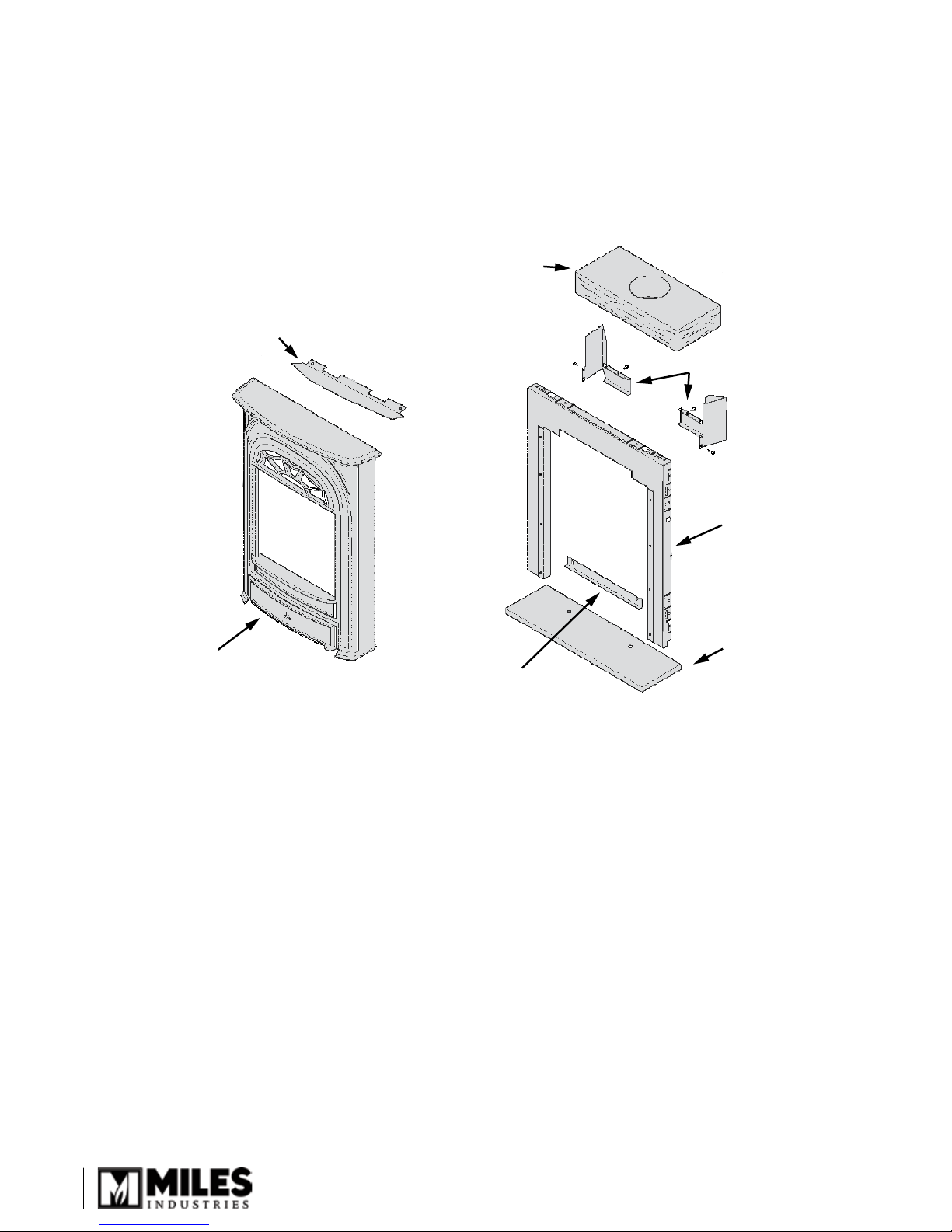
Casting Tolerances
Top Baffle
Front Casting
Rear Base Support
Plinth
Stand-offs (2)
Insulation
Framing Plate
w/Brackets
Due to the nature of cast iron, dimensional consistency may vary from one unit to the next and some variation
in surface nish and atness is to be expected. We have done our best to control and make allowance for this;
however some variation is inevitable.
Kit Contents
1 Front Casting Assembly
1 Top Bafe
1 Framing Plate w/Brackets
1 Plinth
1 Rear Base Support
1 ZC stand-off LH
1 ZC stand-off RH
1 Insulation Layer
1 Pack of Screws
2
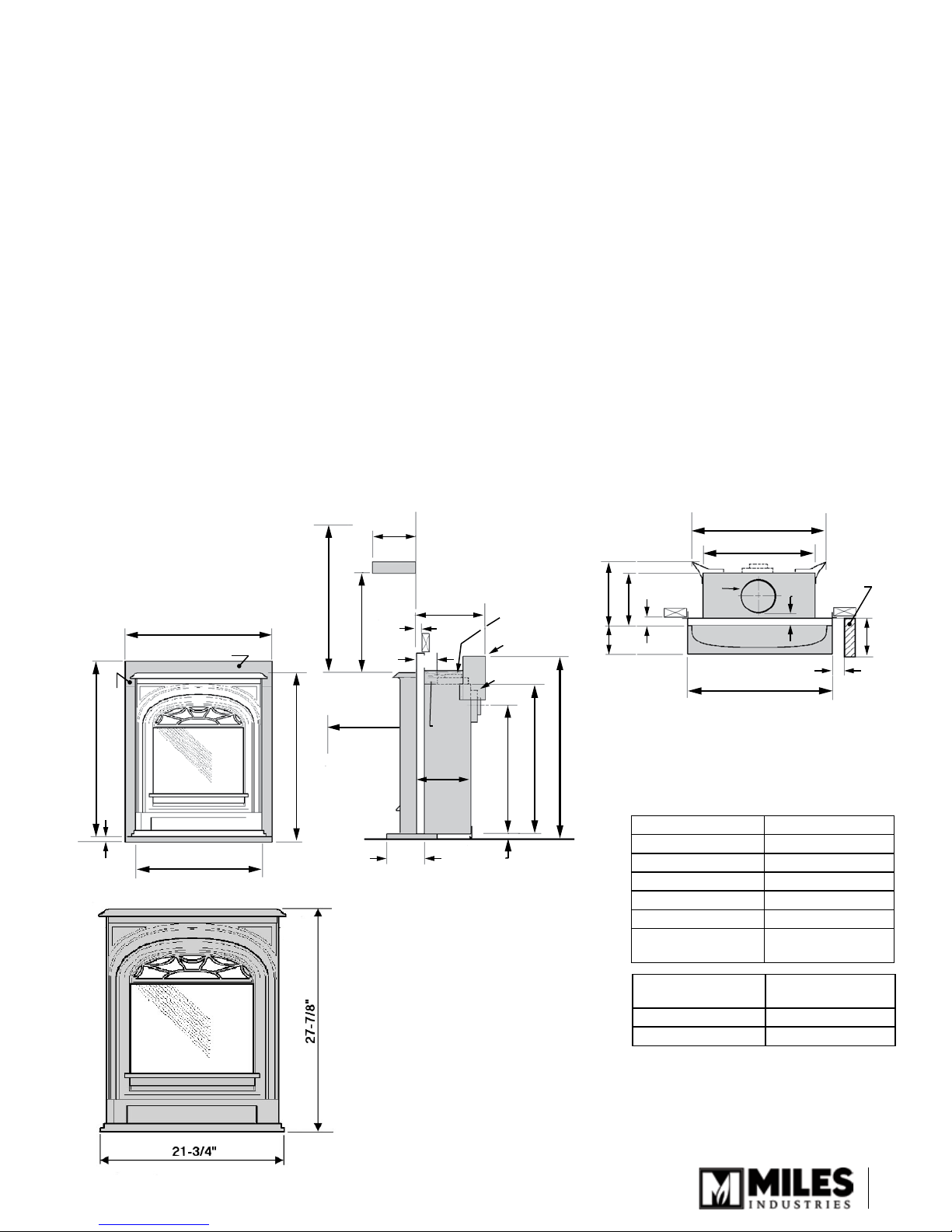
26”
(framing plate)
(framing plate)
31-1/4”
21-3/4”
(cast front)
(cast front)
27-7/8”
7/8”
High
raised
plinth
Ceiling
‘A’
‘B’
1” max.
1/2” min.
1” max.
1/2” min.
11” min.
36” min.
36” min. to
combustibles
9”
Mantel
Optional Top Outlet
ZC Stand-offs
6-5/8” dia.
6-5/8”
dia.
21-5/8”
25-1/4”
31”
5”
7/8”
plinth
insul.
2”
26-1/4”
20”
26”
11”
9”
5”
‘D’
‘E’
Mantel
leg
See table
2”
INSTALLATION WITH 530 ENGINE
The Valor model 530 heater with the 536CXB President ZC Cast Front comes ready for installation as a zero
clearance unit into combustible type framing, without need for a separate zero clearance kit. The 530 installed
without the standard zero clearance stand-off spacers may also be installed into existing solid-fuel burning replaces
provided space and local codes permit.
Hearth Requirements
A 7/8” high plinth is supplied to raise the heater and ensure a base at the proper height for the cast front to sit on
regardless of oor nish height. If not using the plinth supplied, you MUST make allowance for oor nish and raise
(shim) the heater up so the bottom of the heater sits at the nished oor/hearth height, otherwise, the cast front will
not sit at the proper height.
A non-combustible hearth is not required in front of this appliance.
Floor Requirements
The 530 heater is approved for installation directly on any combustible material other than soft ooring material
such as carpet or vinyl.
Mantel Requirements
The 536CXB President ZC Cast Front may be installed with a combustible mantel provided clearances are
maintained as indicated in the Dimensions and Clearances below and in the Framing diagrams on the following
pages. Be aware that although safe, some combustible materials and nishes at the listed clearances may, over
time, discolor, warp, or show cracks. Care should be taken when choosing materials—consult your replace dealer.
Dimensions &
Clearances
Mantel depth “A” Min. clearance “B”
Up to 7” 4”
Above 7” up to 8” 5”
Above 8” up to 9” 7”
Above 9” up to 10” 8”
Above 10” up to 12” 9”
More than 12” 9”+extra 1” for every
Mantel leg
projection “D”
Up to 8” 0”
More than 8” 6”
1” depth above 12”
Min. clearance from
appliance side “E”
3
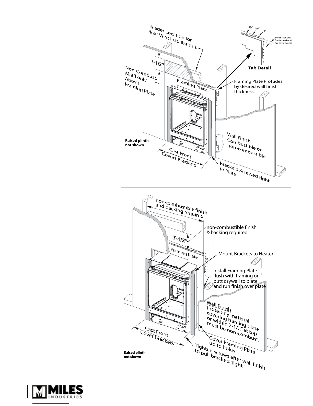
FRAMING
non-combustible finish
and backing required
Tighten screws after wall finish
to pull brackets tight
Cast Front
Framing Plate
Cover brackets
Cover Framing Plate
up to holes
Wall Finish
(note: any material
covering framing plate
or within 7-1/2” at top
must be non-combust.
non-combustible finish
& backing required
Mount Brackets to Heater
Install Framing Plate
flush with framing or
butt drywall to plate
and run finish over plate
Raised plinth
not shown
Framing Plate
Header Location for
Rear Vent Installations
Brackets Screwed tight
to Plate
Wall Finish
Combustible or
non-combustible
Framing Plate Protudes
by desired wall finish
thickness
Bend Tabs out
for desired wall
finish thickness
Tab Detail
Cast Front
Covers Brackets
Non-Combust.
Mat’l only
Above
Framing Plate
Raised plinth
not shown
The President ZC Front comes supplied
with a framing plate for zero clearance
applications. The framing plate is
painted black and may be left exposed
beyond the perimeter of the cast iron
front or may be covered with noncombustible material if desired.
A non-combustible hearth is not
•
necessary in front of this appliance.
The appliance is approved to install
•
directly on wood sub-ooring.
Any framing construction must be
•
clear of stand-offs.
Be aware that the area of 7½” x
•
26¼” (19 cm x 67 cm) immediately
above the framing plate must be
constructed with non-combustible
materials as shown in gures.
Framing plate exposed
4
Framing plate covered
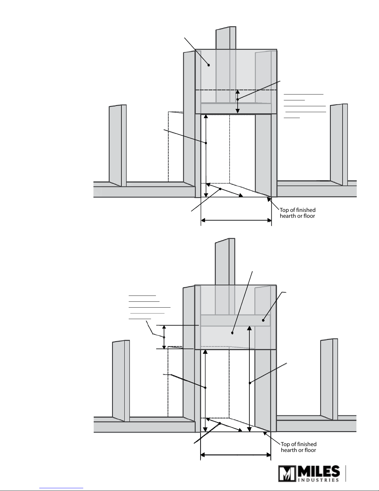
Top of finished
hearth or floor
Wall Finish
26-1/4”
31-1/2”
to header &
wall finish
(includes
plinth -
reduce by
7/8” if not
using plinth)
7-1/2”
minimum
This part of wall
must be
non-combustible
(cement board or
similar)
Minimum 11”
(Allow extra for rear vent elbows)
Top of finished
hearth or floor
Wall Finish
Note: Header
is raised to
accomodate top
vent clearances
39”
to header
(includes
plinth;
reduce by
7/8” if not
using plinth)
31-1/2”
to header
(includes
plinth;
reduce by
7/8” if not
using plinth)
7-1/2” minimum
This part of
wall must be
non-combustible
(cement board
or similar)
Minimum 11”
26-1/4”
Rear vent framing
Top vent framing
5
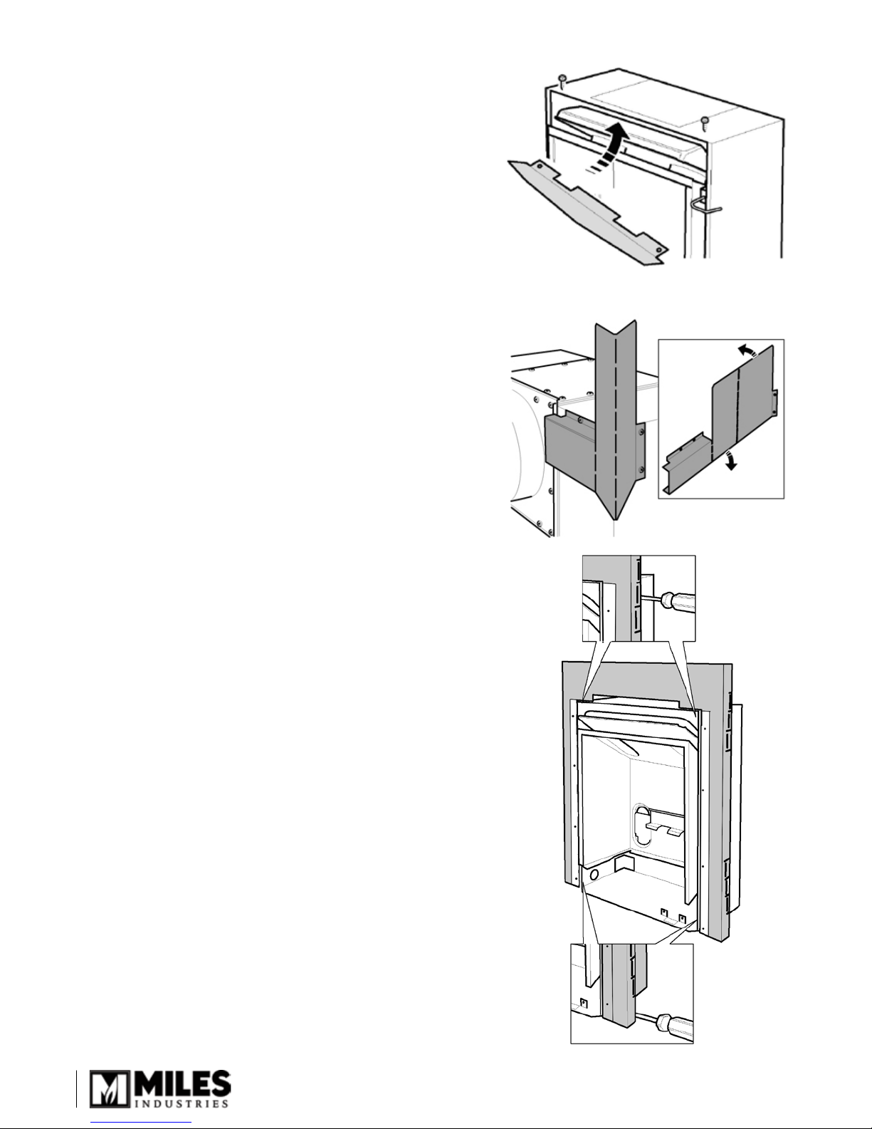
INSTALLATION
1.
Fit the top bafe under the top panel of the appliance
case. Secure with 2 thread forming screws.
2.
Fit the stand-off spacers. The stand-off spacers for
these installations are supplied at. They are left and
right handed.
! Warning: Failure to install the stand-off spacers
may result in a re hazard.
a)
Remove the 2 screws near each of the rear top
corners of the appliance and the 2 screws near
each side of the top back corners.
b)
Bend the spacers as shown.
c)
Screw the spacers to the rear of the appliance
using the screws just removed.
d)
Bend the side wings of the spacers to align the 2
holes in each spacer with those in the appliance
sides. Secure the spacers using the screws just
removed.
3.
Mount the framing plate to the appliance.
4.
Secure the framing plate and brackets to the sides
of the appliance case with 4 thread cutting screws
supplied. Screw from the outside through the access
holes in the framing plate.
Note: There are alternate methods of nishing around
the framing plate—either leaving it exposed or
recessing it and covering it up with the wall nish. See
page 4.
6
 Loading...