

4
aIor
Direct
For
use
Vent
MODEL
wih
Propane
Wall
502CP
Furnace
Gas
only
INSTALLATION
PLEASE
YOUR
FOR
Do
or
and
this
VALOR
ERDINGTON
824
90P
ENG
LAND
not
other
liquids
or
store
flammable
any
HEATING
8IRM)N(.1
or
in
the
other
SAFETY
use
gasoline
vapors
vicinity
appliance.
LEAVE
Vcds
of
poJrrez
THESE
vos
de
cette
you
If
1.
Open
Don’t
2.
switches.
Extmguish
3.
NS1RJCTlONS
p
brocrrrn
r
smell
windows.
touch
INSTRUCTIONS
n
earnp
z
gas:
any
votre
r
olcesson)ore
FOR
electrical
open
WiTH
larrgue
Fançase
YOUR
flame
THE
OWNER
SAFETY
Immediately
4.
supplier.
rb
L
nd
Phc,rr
829
L
BIn
T
rd
VANCIJEP
V7P
(604)
Sveet
3K7
984
call
L)LSRLS
‘es
B
3496
your
Lt
o0OK88t/02
gas
1
-
‘%ISTALLATION
ENERAL
hi,
fireplace
Association
Gas
1.2
outside
Gas
local
the
current
Only
the
SUPPLY
This
wall
The
codes,
installation
CAN-lB
qualified
appliance.
fireplace
Propane
appliance
1
4in.
W.C.
Warning:
regulator
a
tank
L.P.
pressure
1.3
above.
directly
LOCATiON
The
outside
1,3.1
Never
to
fireplace
wall.
THE
The
surface
the
minimum
The
wall
1.32
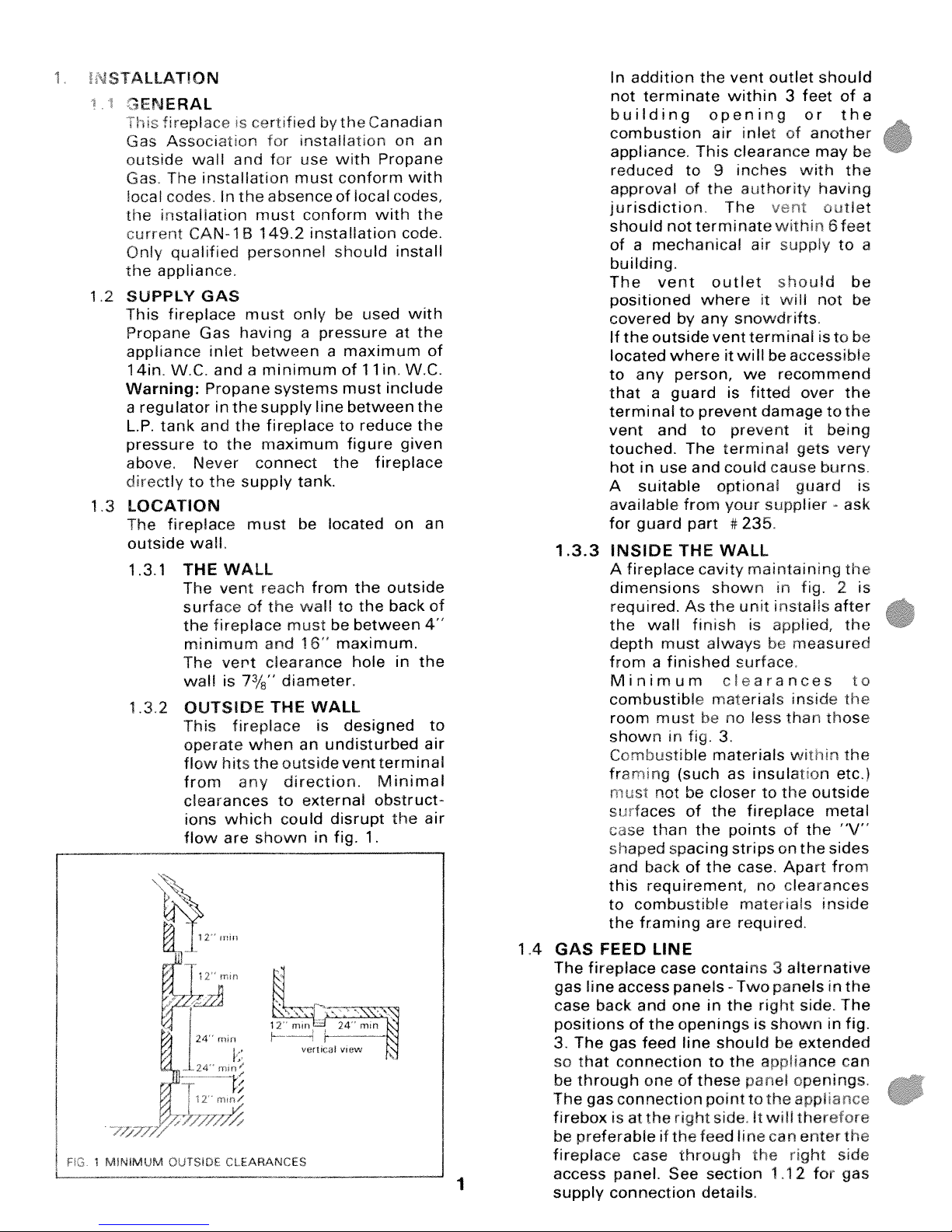
OUTSIDE
This
operate
flow
from
clearances
ions
flow
certified
is
for
for
and
installation
the absence
In
must
149.2
personnel
GAS
must
having
Gas
between
inlet
andaminimum
the
the
systems
supply
fireplace
maximum
Propane
in
and
the
to
connect
the
supply
must
WALL
vent reach
the
of
fireplace
and
vent
clearance
7/8”
diameter.
is
THE
fireplace
when
hits
the
outside
any
to
which
are
could
shown
bytheCanadian
installation
use
must
conform
installation
only be
pressure
a
a
line
the
tank.
located
be
from
wall
must
be
16”
WALL
is
undisturbed
an
direction.
external
disrupt
in
fig.
Propane
with
conform
of
tocal
with
should
used
maximum
in.
of
11
must
include
between
to
reduce
figure
fireplace
outside
the
the
to
back
between
maximum.
hole
designed
terminal
vent
Minimal
obstruct
the
1.
on
with
codes,
the
code.
install
with
the
at
W.C.
the
the
given
on
in
the
an
of
an
4”
air
air
of
to
In
addition
not
terminate
building
combustion
appliance.
reduced
approval
the
This
to
of
opening
air
9
the
jurisdiction
should
not
terminate
ofamechanical
vent
within
inlet
clearance
inches
authority
The
air
outlet
3
of
vt
within
supply
should
feet
or
another
may
with
having
it
of
the
the
outlet
6
feet
to
a
be
a
building.
where
by
where
person,
guard
prevent
to
The
and
from
part
THE
cavity
outlet
any
vent
it
is
prevent
to
terminal gets
could
optional
your
#
WALL
The
vent
positioned
covered
If
the
outside
located
any
to
that
a
terminal
vent
and
touched.
hot
in
use
suitable
A
available
for
guard
1
.33
INSIDE
fireplace
A
dimensions shown
required.
the
depth
wall
must
As
finish
the
always
should
will
it
not
snowdrifts
terminal
is
to
willbeaccessible
recommend
we
fitted
damage
cause
over
it
to
being
burns.
guard
supplier
235
maintaining
fig.
in
unit
is
installs
applied,
be
after
measured
be
be
be
the
the
very
ask
the
2
the
is
is
fromafinished surface.
Minimum
combustible
room
must
shown
in
Combustible
framing
r
ist
not
su
faces
than
case
shaped
and
this
to
the
spacing
backofthe
requirement,
combustible
framing
fig.
(such
be
of
the
clearances
materials
no
be
3.
materials
as
closer
the
points
strips
case.
are
required.
than
less
insulation
the
to
fireplace
of
on
Apart
no
clearances
materials
inside
wit[vn
outside
the
the
to
the
those
the
etc.)
metal
“V”
sides
from
inside
12mm
veil
//
Zi2
I
CLEARANCES
c.ai
view
14GAS
—
—
1
FEED
The
fireplace
gas
line
access
case
back
positions
The
3.
that
so
be
through
The
firebox
be
preferableifthe
fireplace
access
supply
gas
connection
connection
gas
isatthe
panel.
connection
of
case
LINE
contains
case
panels
and
one
the
openings
feed
line
oneofthese
right
feed
through
See
details.
Two
the
in
should
the
to
point
side
line
section
alternative
3
panelsinthe
right
side. The
is
shown
extended
be
appliance
openings.
panel
the
applia
to
will
therefore
It
enter
can
te
right
1
12
for
in
fig.
can
cc
the
side
gas

FIG.2FRAMING
from
28
hearth
(Installed
covers
291/s”
level.
28/8
Max)
finished
Unit
Mm
CEILING
ILL/JILL/I
4
36
Mir
6Max
Mantle
F-
Mm
36’
7
/
/
HG
3
CLEARANCES
fO
—p
/
7
FINISHED
COMBUSTIBLE
7
/
HEARTH
Y//
7
/
LEVEL
MATERIALS
7
/
4’
13/16
1’
7
/
/
GAS
&
LINE
AREAS
/
7
7
11’/2’
CENTER
FIREPLACE
OF
GAS
ACCESS
OPENINGS
7
7
/
7
BACK
OF
111/2
LINE
LINE
7
7
FIREPLACE
4•
j4
12
7
‘
‘
‘
2
FIREPLACE
5
The
rirepace
case
unit
Top
1
Pacia
I
Thin
1
sealing.
Thick
1
sealing.
Thick
1
wall
Ceramic
5
Ceramic side
2
Air
1
Vent
3
Outer vent
1
Bag
1
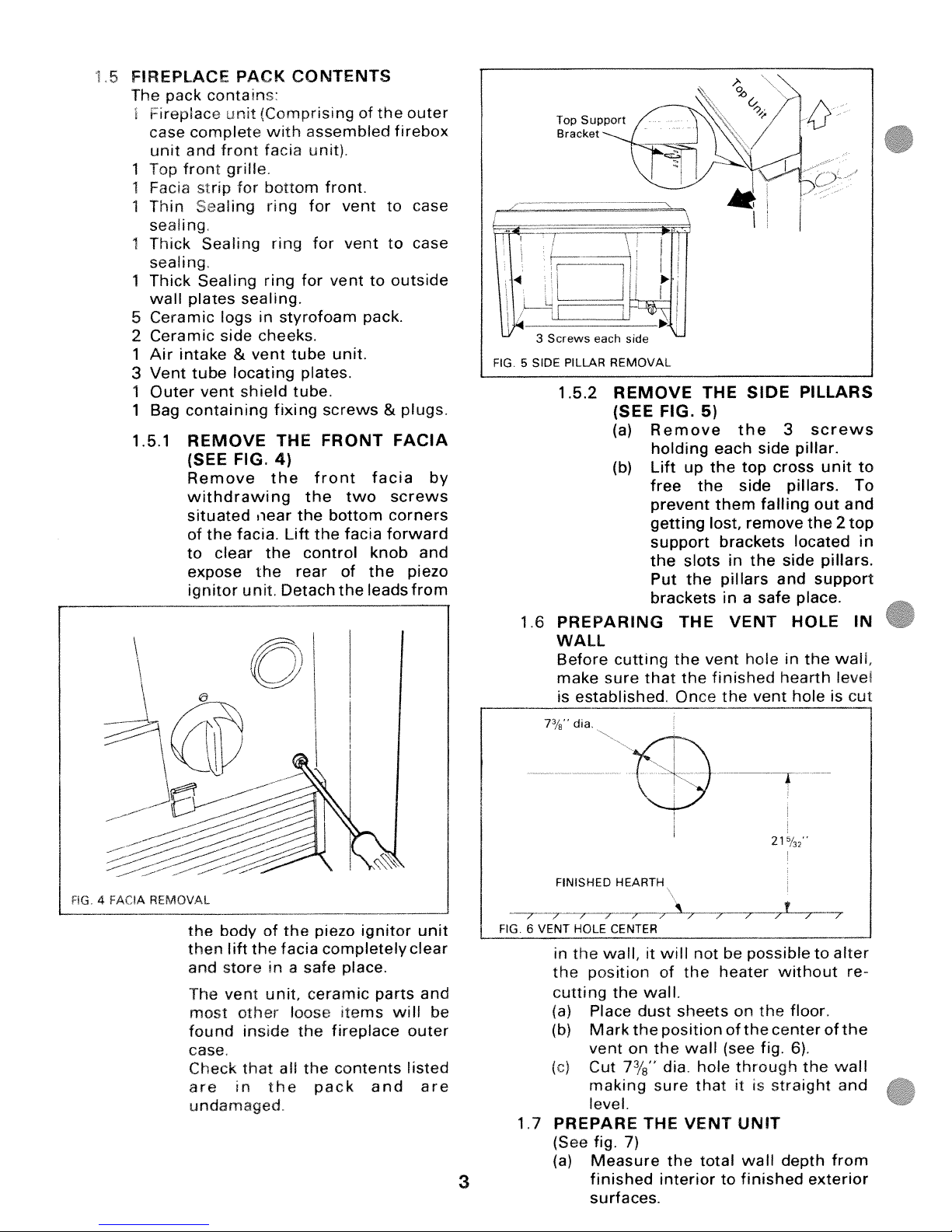
1.5.1
pack
contans
complete
and front
front
strip
Caling
Sealing
Sealing
plates
intake
tube
containing
REMOVE
(SEE
Remove
withdrawing
situated
of
the
clear
to
expose
ignitor
PACK
unit
grille.
for
sealing.
logs
&
locating
shield
FIG.
facia.
unit.
CONTENTS
(Comprising
assembled
with
facia
unit).
bottom
ring
for
ring
ring
for
in
styrofoam
cheeks.
vent
tube
plates.
tube.
fixing
THE
4)
the
the
the
near
Lift
control
the
the
rear
Detach
front.
vent
for
vent
vent
unit.
screws
FRONT
front
two
bottom
facia
the
of
the
of
the
firebox
to
to
outside
to
pack.
plugs.
&
FACIA
facia
screws
corners
forward
knob
the
leadsfrom
outer
case
case
by
and
piezo
3
FIG.5SIDE
1.6
7’
Screws
each
PILLAR
REMOVAL
1.5.2
REMOVE
(SEE
(a)
(b)
PREPARING
WALL
Before
make
is
cutting
sure that
established.
dia.
side
I
FIG.
Remove
holding
Lift
up
free
prevent
getting
support
the
slots
Put
the
brackets
THE
the
the
Once
THE
5)
each
the
the
them
lost,
brackets
pillars
inasafe
vent
finished
the
1
SIDE
the
side
top
side
falling
remove
in
the
VENT
hole
vent
PILLARS
screws
3
pillar.
cross
pillars.
out
the
located
side
and
support
place.
HOLE
in
the
hearth
holeiscut
unit
and
2
top
pillars.
waiL
eve
to
To
in
IN
in
the
facia
a
loose
the
piezo
safe
ceramic
the
then
and
The
most
found
body
lift
store
vent
other
of
the
unit,
inside
case.
Check
are
that
in
the
all
the
pack
undamaged
ignitor
completely
place.
parts
Items
fireplace
contents
and
will
unit
clear
and
be
outer
listed
are
3
/ /
FIG6VENT
in
the
cutting
(a)
(b)
(c)
1.7
PREPARE
(See
(a)
FINISHED
/
HOLE
the
HEARTH
/
CENTER
wall,
position
the
Place
Marktheposition
vent
Cut
making
level.
fig.
Measure
finished
surfaces.
7
on
7/’.
7)
it
wall.
dust
THE
/
will
the
of
sheets
the
wall
dia
sure
VENT
the
interior
/
/
not
be
heater
on
ofthecenterofthe
(see
through
hole
that
itISstraight
UNIT
total
wall
to
finished
21
/
/
possible
without
the
fig.
depth
32
/
floor.
6).
the
exterior
to
/
alter
re
wall
and
from
 Loading...