

Valor 502CN Installation Instructions Manual
Direct
9
aIor
Vent
Wall
Furnace
APPROVE
R
For
MODEL
use
with
502CN
Natural
Gas
INSTALLATION
PLEASE
FOR
YOUR
Do
not
store
or
other
and
this
VALOR
ERDINGTON,
9QP
824
ENGLAND
liquids
or
any
HEATING
BRMNGHAM
flammable
or
in
the
other
SAFETY
gasoline
use
vapors
vicinity of
appliance.
LEAVE
Vous
pourrez
THESE
vous
de
cette
If
you
1.
Open
Don’t
2.
switches.
Extinguish
3.
INSTRUCTIONS
smell
un
chez
gas:
procurer
brochure
windows.
touch
INSTRUCTIONS
YOUR
flame.
THE
OWNER
SAFETY
Immediately
4.
supplier.
Distnbuted
NORTH
by
Third
829
Phone (6O4
exempiaire
votre
electrical
any
WITH
en
langue Francaise
concessionaire.
FOR
open
HSINDUSTRiES
West
Street
VANCOUVER
V7P3K7
9843496
call
BC.
your
LTD
AOOKRR9/(t9
gas
1,
INSTALLATION
GENERAL
1.1
installation
for
use
must
conform
installation
only
a
be
from
wall
must
16”
diameter.
WALL
an
outside
direction.
external
to
could
min
12
vertical
bythe
pressure
a
located
be
is
undisturbed
disrupt
fig.
in
is
and
the
In
having
inlet
and
a
WALL
vent
fireplace
vent
is
7/8”
fireplace
hits
any
certified
for
absence
must
149.1
personn
must
between
minimum
must
reach
the
of
and
clearance
THE
when
the
1.2
1.3
This
fireplace
Gas
Association
outside
Gas.
local
the
current
Only
the
wall
The
codes.
installation
CAN-lB
qualified
appliance.
SUPPLY
fireplace
This
Natural
Gas
appliance
W.C.
8in.
LOCATION
fireplace
The
outside
1.3.1
wall.
THE
The
surface
the
minimum
The
wall
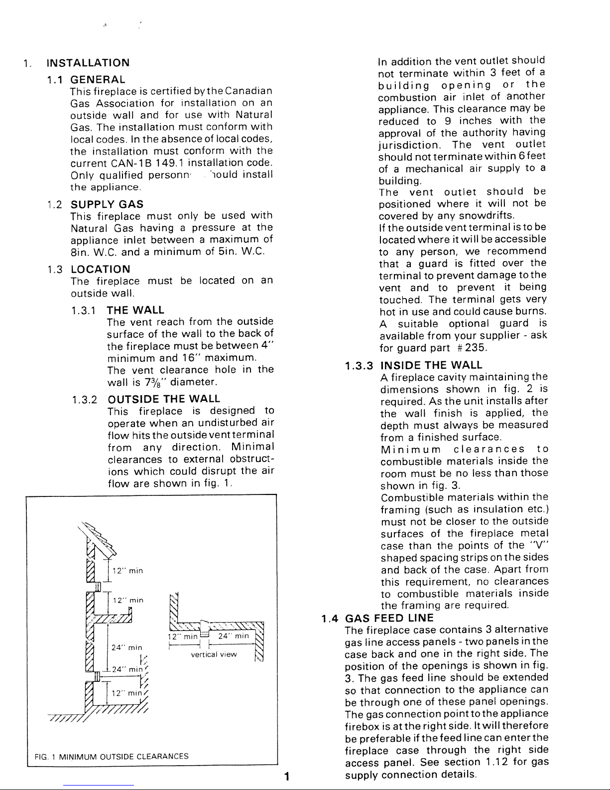
1.3.2
OUTSIDE
This
operate
flow
from
installation
GAS
clearances
which
ions
shown
are
flow
FIG.
MINIMUM
1
OUTSIDE
CLEARANCES
Canadian
with
Natural
conform
of
local
codes,
with
iould
be
used
maximum
of
5in.
W.C,
on
the
outside
the
to
back
between
maximum.
hole
designed
vent
terminal
Minimal
obstruct
the
1.
mn
24’
view
on
with
the
code.
install
with
the
at
the
in
N
an
an
4”
air
air
of
of
to
3
of
vent
within
supply
should
feet
or
another
may
with
having
outlet
6
of
the
the
feet
to
a
be
a
addition
In
not
terminate
building
combustion
appliance.
reduced
approval
jurisdiction.
should
of
not
mechanical
a
the
opening
air
This
to
9
of
the
The
terminate
outlet
vent
within
inlet
clearance
inches
authority
air
building.
not
isto
to
being
it
burns.
those
outside
metal
the
inside
in
for
the
the
very
ask
-
the
2
after
the
the
the
etc.>
“V”
sides
from
in
the
The
fig.
can
the
side
gas
be
be
be
is
is
to
The
vent
positioned
covered
outside
the
If
located
any
to
a
that
terminal
vent
and
touched.
in
hot
A
use
suitable
available
for
guard
1.3.3
INSIDE
fireplace
A
dimensions
required.
wall
the
depth
from
must
a
Minimum
combustible
room
must
shown
Combustible
framing
not
must
surfaces
than
case
shaped
back
and
this
requirement,
to
combustible
framing
the
FEED
GAS
1.4
The
fireplace
line
gas
back
case
position
The
3.
that
so
through
be
gas
The
firebox
preferable
be
fireplace
access
1
supply
LINE
case
access
and
the
of
feed
gas
connection
one
connection
the
at
is
if
case
panel.
connection
outlet
where
any
by
ventterminal
where
person,
guard
prevent
to
to
The
and
optional
from
part#235.
THE
cavity
shown
the
As
finish
always
finished
materials
be
in
fig.
materials
(such
be
closer
the
of
the
spacing
the
of
are
contains
panels
in
one
openings
line
to
these
of
point
side.
right
feed
the
through
section
See
details.
it
is
terminal
could
your
WALL
clearances
no
3.
the
should
should
will
it
snowdrifts.
be
we
accessible
recommend
will
fitted
damage
prevent
cause
supplier
maintaining
in
unit
installs
is
applied,
be
surface.
than
less
as
insulation
the
to
fireplace
case.
of
on
Apart
no
clearances
points
strips
materials
required.
alternative
3
panels
two
-
right
is
shown
be
the
appliance
panel
the
to
It
will
line
can
the
1.12
over
gets
guard
fig.
measured
inside
within
the
side.
extended
openings.
appliance
therefore
enter
right
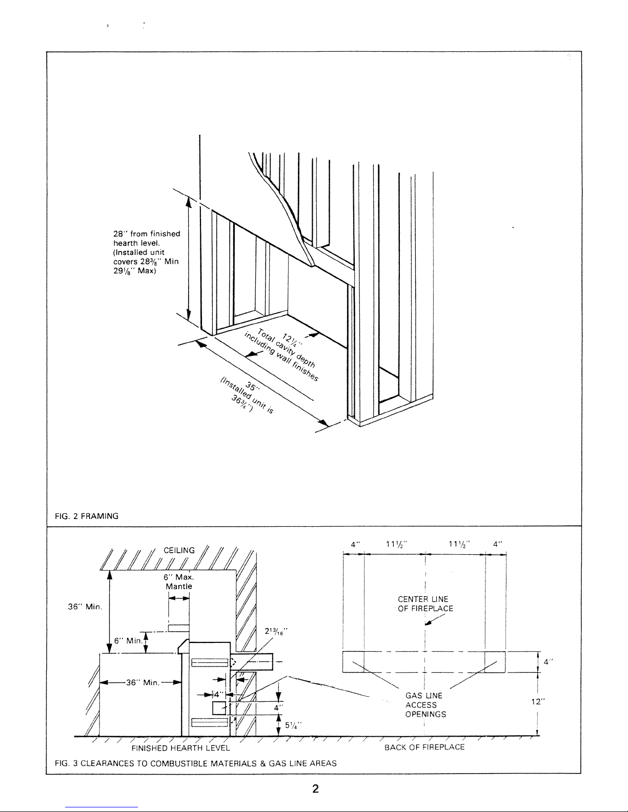
FIG.
FRAMING
2
from
28”
hearth
(Installed
covers
29’/”
level.
28%
Max)
finished
unit
Mm
Mm.
36”
FINISHED
FIG.
3
CLEARANCES
TO
HEARTH
COMBUSTIBLE
LEVEL
MATERIALS
&
2’’,’’
GAS
LINE
AREAS
2
4’’
Lç
11
SACK
!‘
CENTER
FIREPLACE
OF
GAS
ACCESS
OPENINGS
OF
1 1
LINE
f
UNE
FiREPLACE
‘/2’
4”
12”
1.5
FIREPLACE
The
1
1
1
1
1
1
5
2
1
3
1
1
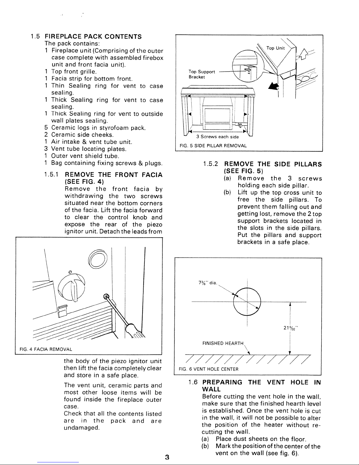
1.5.1
pack
Fireplace
case
complete
and
unit
Top
front
Facia
Thin
Sealing
sealing.
Thick
sealing.
Thick
wall
plates
Ceramic
Ceramic
Air
intake
Vent
tube
Outer
Bag
containing
REMOVE
(SEE
Remove
withdrawing
situated
of
to
expose
ignitor
contains:
unit
front
grille.
strip
Sealing
Sealing
logs
side
&
locating
vent
FIG.
the
facia.
clear
PACK
(Comprising
with
facia
for
bottom
ring
ring
ring
sealing.
in
styrofoam
cheeks.
vent
shield
fixing
THE
4)
the
near the
Lift
the
the
unit.
Detach
CONTENTS
of
assembled
unit).
front.
for
vent
for
vent
for
vent
pack.
tube
unit.
plates.
tube.
screws
FRONT
front facia
the
two
bottom
the
facia
control
rear
of
the
the
to
to
to
&
corners
forward
knob
the
leads
outer
firebox
case
case
outside
plugs.
FACIA
screws
and
piezo
from
by
Top
Support
Bracket
3
FIG.5SIDE
___J
Screws
PILLAR
1.5,2
each
side
REMOVAL
REMOVE
(SEE
(a)
(b)
FIG.
Remove
holding
Lift
up
free
prevent
getting
support
the
slots
Put
the
brackets
THE
5)
each
the
the
them
lost,
brackets
pillars
inasafe
SIDE
the
top
side
remove
in
side
falling
the
3
pillar.
cross
pillars.
located
side
and
place.
PILLARS
screws
unit
To
out and
the
2top
pillars.
support
to
in
FIG.4FACIA
REMOVAL
the
then
and
The
most
found
bodyofthe
lift
the
facia
store
in
a
vent
unit,
other
loose
inside
piezo
completely
safe
ceramic
the
fireplace
case.
that
in
the
all
the
pack
contents
Check
are
undamaged.
ignitor
place.
items
parts
and
will
unit
clear
and
outer
listed
are
be
dia,
7/’
212
FIG.
/
6
1.6
/
VENT
FINISHED
///
HOLE
PREPARING
HEARTH
CENTER
.4
//
THE
/7
////
VENT
HOLE
IN
/
WALL
Before
make
is
in
the
cutting
(a)
(b)
3
cutting
sure
established.
wall,
the
position
the
Place
Mark
vent
dust
the
on
that
will
it
of
wall.
position
the
the
vent
the
finished
Once
the
not
the heater
sheets
wall
be
on
of
(see
hole
the
in
hearth
vent
possible
without
the
center
fig.
the
hole
floor.
6).
to
wall,
level
is
alter
of
cut
re
the
 Loading...