

Valor 492CNA, 492CNB, 492CPA, 492CPB, 492CBC Installer's & Owner's Manual
...
n~an~ronr
GAS
FIRED VENTED
ROOM
HEATERS
r
WARNING: Hthe information
in
this
manual is not followed exactly,
a
fire
orexplosion may result causing
personal injury or loss of life.
-Do not store or use gasoline
or other flammable vapors
and liquids in the vicinity of
this or any other appliance.
-WHAT
TO
DO
IF
YOU
SMELL
GAS
Open Windows.
Do not
try
to light any
appliance.
Do not touch any electrical
switch; do not use any phone
in
your building.
Extinguish any open flame
Immediately call your gas
supplier from
a
neighbor's
phone. Follow the gas
supplier's instructions.
If you cannot reach your gas
supplier, call the fire
department.
-Installation and service must be
performed by a qualified installer,
service agency or the gas supplier.
INSTALLERS
&
OWNERS MANUAL
INSTALLER - PLEASE LEAVE THIS MANUAL WITH THE OWNER
(Vous pourrez vous procurer un manuel en langue Fran~aise chez votre concessionaire)
600A287
CAUTlON
Dueto high temperatures,the room heater should
Keep the area below the front apron and the
!
be
located out of traffic and away from furniture
rectangular slots down each side of
the
case
and draperies.
back clear to prevent obstruction of the air flow
-1
for combustion.
Children and adults should be alerted to the
hazards of high surfacetemperatures and shou:d
All vented room heaters require a source of fresh
stay away to avoid bums or clothing ignition.
air in order to vent properly. The venting system
should be checked periodically.
Young children should
be
carefully supervised
Recent trends in home improvement and
new
when they are in the same room as the room
tighterconstructiontechniqueshavecontributed
heater.
to problems with venting. If you suspect that
e
your heater is
not
venting properly, do not operate
Clothing or other flammable material should not
and
seek
expert advice.
be
placed on or near
the
room heater.
For added safety, this heater is equipped with a
vent sensor which will react to incorrect venting
The glass window
unit
must be
put
back in place
by shing d&n the
gas
supply.
prior to operating the heater if
it
has been removed
for servicing or cleaning.
Do not use this heater if any part has been under
water. Immediately call a qualified service
This room heater should beinstalled and repaired
technician to inspect the heater and to replace
by a qualified service person.
any part of the control system and any gas
control which has been under water.
The heater should be inspected before use and
at
least annually by a professionalsewice person.
If any chanaes aremade ta the room construction
More frequent cleaning may be required due to in thevicinity of the heater after installation (e.g.
excessive lint from carpetting, bedding material, additional mantle etc.), mn!te sure that such
-
etc.
It
is imperative
that
control compartments,
changes conform to the installation requirements
burners and circulating air passageways of the in this manual.
heater be kept clean.
When equipped
with
the optional vent primer
Keep curtains, clothing, furniture and other
(Part #300VP) or power vent kit (Part
#501
PVK),
flammable materials
at
least36ins (900mm) from
the heater must
be
installed and electrically
the front and top of the heater. grounded in accordance with local codes or, in
the absence of local codes, with the latest edition
Keep
the heater area well clear and free from of the National Electrical Code ANSIINFPA 70 (in
combustible materials, gasoline and other
U.S.A.)
or
CSA
C22-1 Canadian Electrical Code.
flammable vapors and liquids.
Never attemptto bum paper or any other material
in the heater.
Note
-
On
first lighting your new heater, there may be a slight odor and the appearance of a small amount of vapor.
This is normal
with
any new gas appliance. It is not harmful and will disappear within a short time.
INSTAUATION
INSTRUCTIONS
1.
GENERAL
This appliance is certified by
the
Canadian
/'.
Gas
Association and the American
Gas
Association for use with natural gas.
The
installation must conform
with
local codes
or, in the absence of local codes,
with
the
current CANICGA1 -B149 Installation Code in
Canada or the current National Fuel
Gas
Code, ANSI 2223.1 in
the
U.S.A
Only qualified
(licensed or trained) personnel should
install the appliance.
The appliance rating plate is on the inner face
of the back panel
at
the left side. There is also
a label giving the serial number, on the
,right
-
side
of
the outer case near the bottom.
Appliance data:-
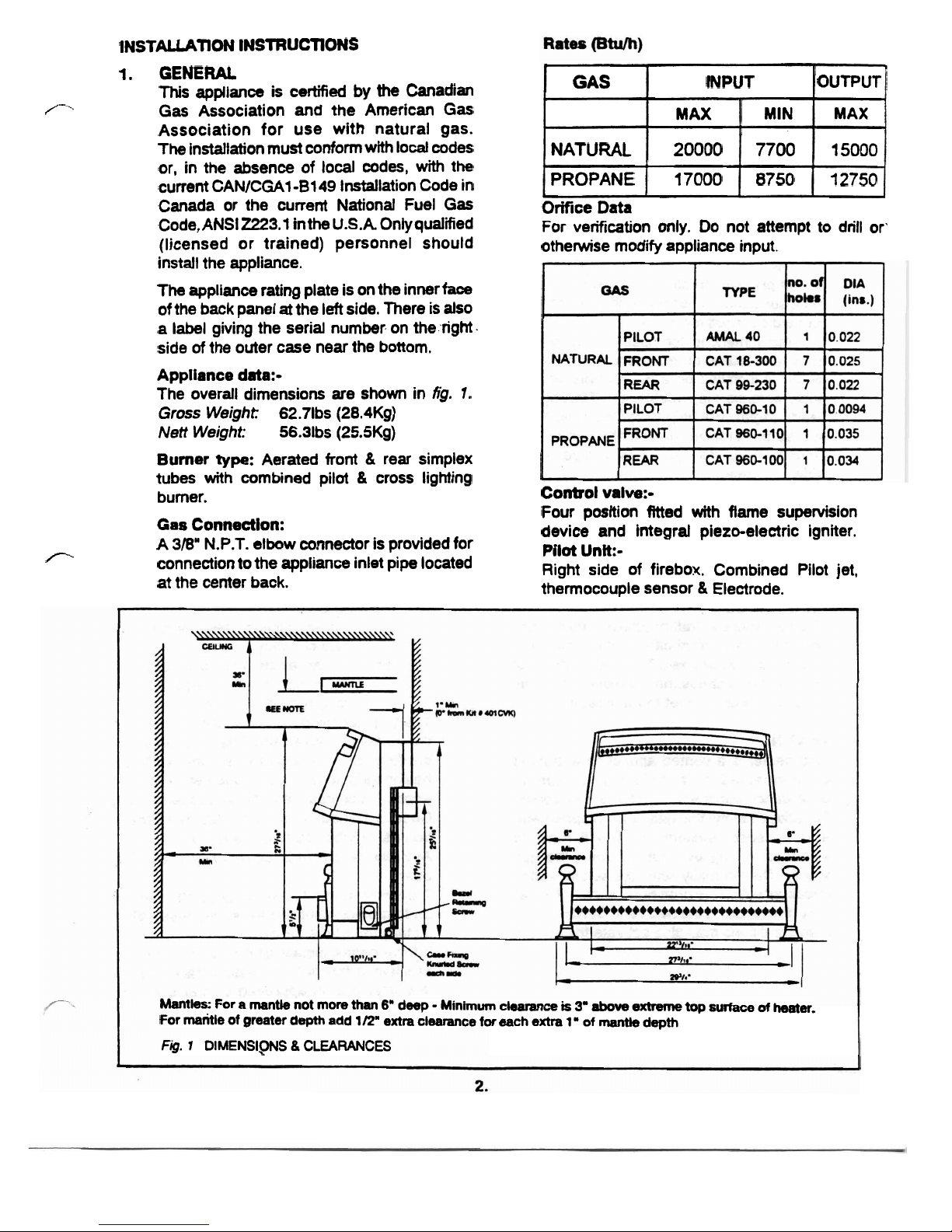
The overall dimensions are shown in
fig.
1.
Gross
Weight:
62.71bs (28.4Kg)
Nett Weight:
56.31bs (25.5Kg)
Burner
type:
Aerated front & rear simplex
tubes with combined pilot
&
cross lighting
burner.
Gas
Connection:
A
3/6"
N.P.T. elbow connector is provided for
r‘
connection to the appliance inlet pipe located
at the center back.
Orifice
Data
For verification only. Do not attempt to drill or'
otherwise modify appliance input.
Control valve:-
Four position fitted with flame supervision
device and integral piezo-electric igniter.
Pilot
Unit:-
Right side of firebox. Combined Pilot jet,
thermocouple sensor
&
Electrode.
1
OUTPUT
MAX
15000
12750
GAS
NATURAL
PROPANE
Mantles:
For a mantle not more
than
6"
deep - Minimum
clearance
is
3'
above
extreme
top
surface
of
heater.
For
mantle
of
greater
depth add
112"
extra
clearance
for
each
extra
1'
of
mantie
depth
Fig.
1
DIMENSIPNS 8 CLEARANCES
INPUT
MAX
20000
17000
MIN
7700
8750
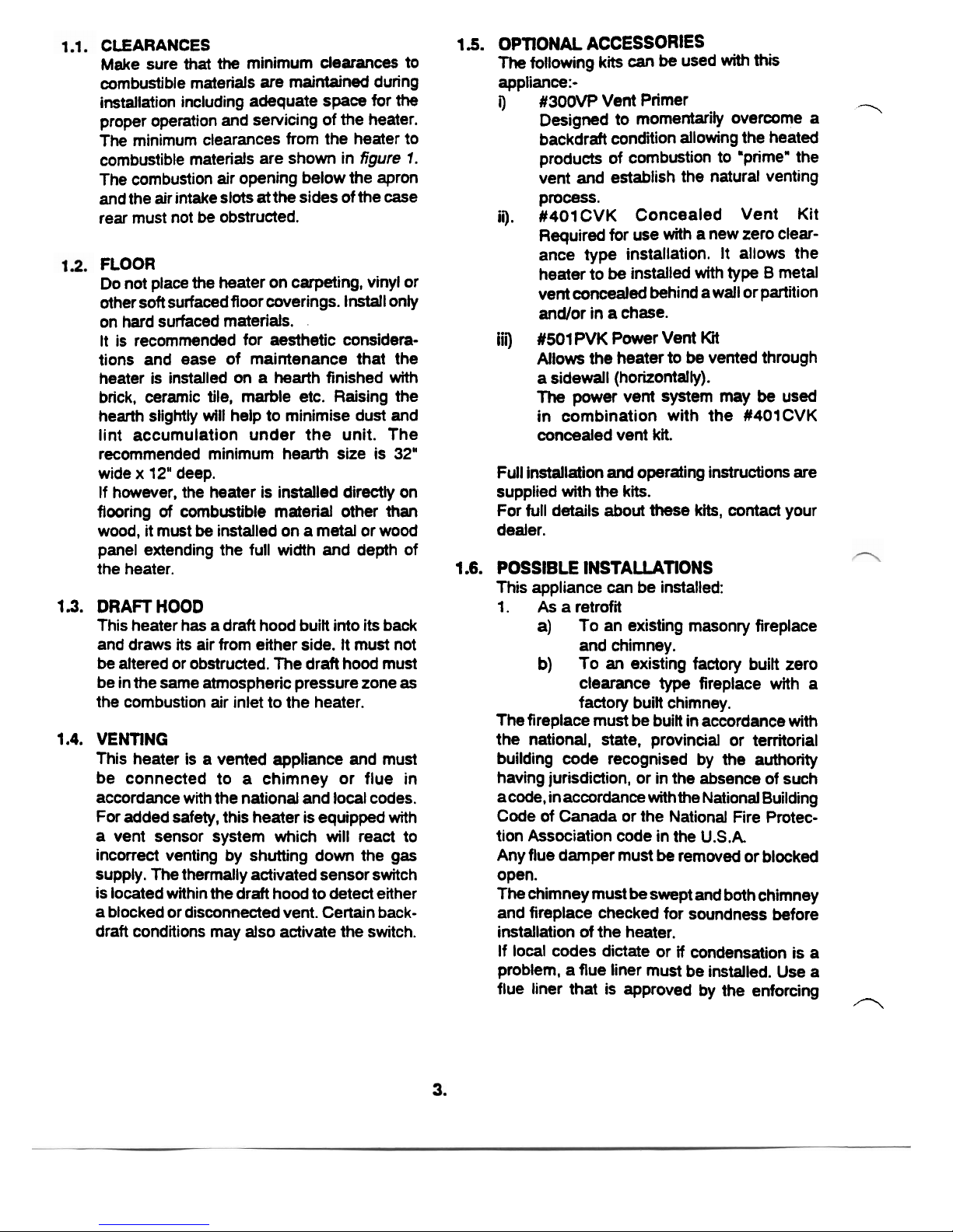
CLEARANCES
Make sure that
the
minimum clearances to
combustible materials are maintained during
installation including adequate space for
the
proper operation and servicing of the heater.
The minimum clearances from the heater to
combustible materials are shown in
figure
7.
The combustion air opening below the apron
and the air intake slots
at
the sides of the case
rear must not
be
obstructed.
FLOOR
Do not place the heater on carpeting, vinyl or
other soft surfaced
floor coverings. Install only
on hard surfaced materials.
It is recommended for aesthetic considera-
tions and ease of maintenance that the
heater is installed on a hearth finished
with
brick, ceramic tile, marble etc. Raising the
hearth slightly
will
help to minimise dust and
lint accumulation under the unit. The
recommended minimum hearth size is
32"
wide x 12" deep.
If however, the heater is installed directly on
flooring
of
combustible material other than
wood, it must
be
installed on a metal or wood
panel extending the full width and depth of
the heater.
1.3.
DRAFT
HOOD
This heater has a draft hood built into its back
and draws its air from either side. It must not
be altered or obstructed. The draft hood must
be in the same atmospheric pressure zone
as
the combustion air inlet to the heater.
1.4.
VENTING
This heater is a vented appliance and must
be connected to a chimney or flue in
accordance with the national and local codes.
For added safety, this heater is equipped with
a vent sensor system which
will
react to
incorrect venting by shutting down the gas
supply. The thermally activated sensor switch
is located within the draft hood to detect either
a blocked or disconnected vent. Certain back-
draft conditions may also activate the switch.
1
b.
OPTlONAL ACCESSORIES
The
following kits
can
be
used
with
this
appliance:-
i)
#300VP
Vent Primer
-
Designed to momentarily overcome
a
backdraft condition allowing the heated
products of combustion to 'prime" the
vent and establish the natural venting
process.
ii).
#401CVK Concealed Vent Kit
Required for use with a new zero clearance type installation. It allows the
heater to
be
installed with type B metal
vent concealed behind a wall or partition
andlor in a chase.
iii)
#SO1
PVK
Power Vent
Kit
Allows the heater to be vented through
a sidewall (horizontally).
The
power vent system may be used
in combination with the
#401CVK
concealed vent kit.
Full installation
and
operating instructions are
supplied with the
ki.
For full details about these
kits,
contact your
dealer.
1.6.
POSSIBLE INSTALLATIONS
This appliance can be installed:
1.
As a retrofit
a)
To an existing masonry fireplace
and chimney.
b)
To an existing factory built zero
clearance type fireplace with a
factory built chimney.
The fireplace must be built in accordance
with
the national, state, provincial or territorial
building code recognised by the authority
having jurisdiction, or in the absence of such
a code, in accordance with
the
National Building
Code
of
Canada or the National Fire Protec-
tion Association code in the
U.S.A
Any flue damper must
be
remwed or blocked
open.
The chimney must
be
swept and both chimney
and fireplace checked for soundness before
installation of the heater.
If local codes dictate or
if
condensation is a
problem, a flue liner must be installed. Use a
flue liner that is approved by the enforcing
0
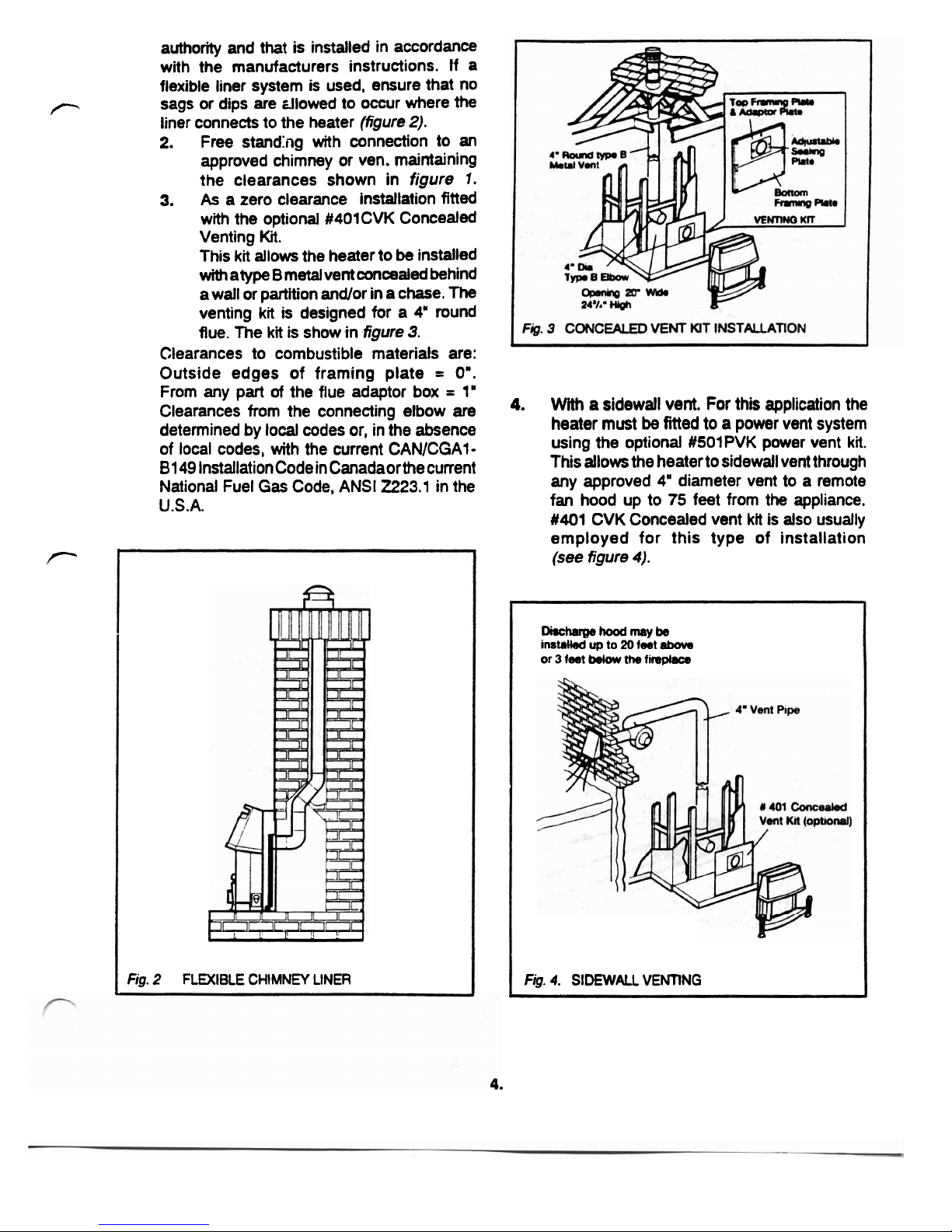
authority and that is installed in accordance
with the manufacturers instructions.
If a
flexible liner system is used, ensure that no
P
sags
or
dips are zllowed to occur where
the
liner connects to the heater
(figure
2).
2.
Free standhg with connection to
an
approved chimney or ven. maintaining
the clearances shown in
figure
I.
3.
As
a zero clearance installation fitted
with the optional
#401CVK Concealed
Venting
Kit.
This
kit
allows the heater to
be
installed
with
atype B metal vent concealed behind
a
wall or partition and/or in a chase.
The
venting
kit
is designed for a
4"
round
flue.
The
kit
is show in
figure
3.
Clearances to combustible materials are:
Outside edges of framing plate
=
0".
I
1
1
I--.-
7
Fig.
2
FLEXIBLE CHIMNEY LINER
Di=hwP-mcrybe
instnW
up
to
20
feet
atwe
or
3
feet
bdow
the
firsplace
Fig.
4.
SIDEWALL
VENTING
From any p&
of
the flue adaptor box
=
1"
Clearances from the connecting elbow are
4.
With
a
sidewall vent. For this application the
determined by local codes or, in the absence
heater must
be
fitted to a power vent system
of local codes, with the current CANICGA1-
using the optional #SOlPVK power vent
kit.
81
49
Installation Code in Canadaorthe current
This allows the heater to sidewall vent through
National Fuel
Gas
Code, ANSI
2223.1
in the
any approved
4'
diameter vent to a remote
U.S.A.
fan hood up to
75
feet from the appliance.
#401
CVK
Concealed vent
ktt
is also usually
P
employed for this type of installation
(see figure
4).
2.
UNPACKING
The
carton contains
the
following:-
1
Heater assembly.
3
Ceramic logs.
1
Flue collar.
1
Pack fixing screws.
2
Plastic
caps
for foot screws.
1
Smoke match tube.
Remove all the items carefully to prevent damage.
Some items may
be
contained in the packaging
fitments
-
Examine the packaging carefully before
discarding. Check that
ail the items are present and
undamaged.
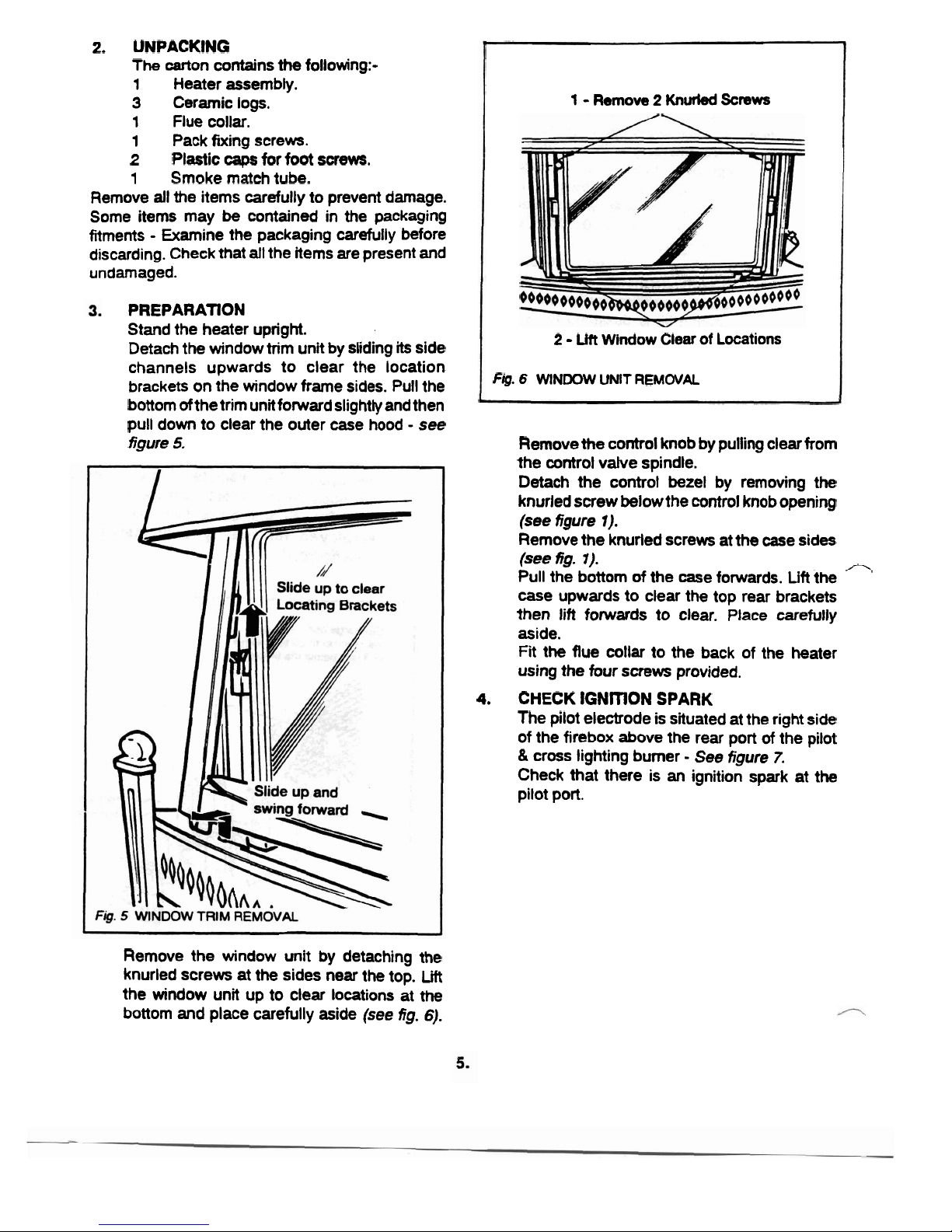
PREPARATION
Stand the heater upright.
Detach the window trim unit by sliding
its
side
channels upwards to clear the location
brackets on the window frame sides. Pull the
bottom
ofthe trim unit forward slightly and then
pull down to clear the outer case hood
-
see
figure
5,
Remove the window unit by detaching the
knurled screws at the sides near the top.
Lift
the window unit up to clear locations at
the
bottom and place carefully aside
(see
fig.
6).
1
-
Remove 2 Knurled Screws
2 - Lilt
Window
Clear
of
Locations
Fig. 6 WINDOW
UNIT
REM
WAl
Remove the control knob by pulling clear from
the control
valve spindle.
Detach the control bezel by removing the
knurled screw below the control knob opening
(see
figure
1).
Remove the knurled screws at the case sides
(see
fig.
7).
/7
Pull the bottom
of
the case forwards.
Lift
the
case upwards to clear the top rear brackets
then lift forwards to clear. Place carefully
aside.
Fit
the flue collar to the back of the heater
using the four screws provided.
4.
CHECK
IGNITION SPARK
The pilot electrode is situated at the right side
of the firebox above the rear port
of
the pilot
&
cross lighting burner
-
See
figure
7.
Check that there is
an
ignition spark at the
pilot port.
 Loading...