

Valor 474 Valentia Installation And Owner's Manual
08/52395/0
© GDC Group Ltd. 2014
Model 474 Valentia
Balanced Flue
ROOM SEALED RADIANT / CONVECTOR
GAS FIRE
INSTALLER: Please leave this guide with the owner
INSTALLATION AND OWNER GUIDE
We trust that this guide gives
sufficient details to enable this
appliance to be installed, operated
and maintained satisfactorily.
However, if further information is
required, our Valor Technical
Helpline will be pleased to help.
Telephone 0844 879 35 88
(National call rates apply in the
United Kingdom).
In the Republic of Ireland Telephone
01 842 8222 .
DON’T FORGET
To r
e
gister y
ou
r guarantee!
C
all 08
00 597 8500

© GDC Group Ltd.
All rights reserved. No part of this publication may be reproduced in any material form
(including photocopying), stored in any medium by electronic means (including in any
retrieval system or database) or transmitted, in any form or by any means, whether
electronic, mechanical, recording or otherwise, without the prior written permission of
the copyright owner.
Applications for the copyright owner's permission to reproduce any part of this
publication should be made, giving details of the proposed use, to the following
address: The Marketing Communications Manager, GDC Group Ltd, Millbrook House,
Grange Drive, Hedge End, Southampton, SO30 2DF.
Warning: Any person who does any unauthorised act in relation to a copyright work
may be liable to criminal prosecution and civil claims for damages.
Because our policy is one of constant development and improvement, details may vary
slightly from those given in this publication
Page 2
© GDC Group Ltd. 2014
THIS APPLIANCE IS FOR USE WITH NATURAL GAS (G20).
UNDER NO CIRCUMSTANCES IS THIS APPLIANCE TO BE CONVERTED TO
LPG. AN LPG CONVERSION KIT DOES NOT EXIST FOR THIS APPLIANCE
THIS APPLIANCE IS SUITABLE ONLY FOR INSTALLATION IN THE UNITED
KINGDOM (GB) AND THE REPUBLIC OF IRELAND (IE).
Safety First.
Valor fires are CE Approved and designed to meet the appropriate British Standards
and Safety Marks.
Quality and Excellence.
All Valor fires are manufactured to the highest standards of quality and excellence
and are manufactured under a BS EN ISO 9001 quality system accepted by the
British Standards Institute.
The Highest Standards
Valor Fires is a member of SBGI and HHIC (Heating and Hot water Industry Council)
that work to ensure high standards of safety, quality and performance.
Careful Installation
This gas fire must be installed by a competent GAS SAFE REGISTER engineer (GAS
SAFE REGISTER or CORGI engineer outside of UK) in accordance with our installer
guide and should not be fitted directly on to a carpet or floor of combustible material.
Page 3
© GDC Group Ltd. 2014

Page 4
© GDC Group Ltd. 2014
INSTALLER GUIDE
INSTALLER GUIDE
FOR OWNER GUIDE SEE PAGES 24 TO 35

CONTENTS
Section Heading Page
INSTALLER GUIDE 4 - 22
OWNER GUIDE 24 - 35
1. SAFETY 7
2. ACCESSORY LIST 8
3. APPLIANCE DATA AND EFFICIENCY 8
3.1 General information. 8
3.2 Efficiency. 9
4. GENERAL INSTALLATION REQUIREMENTS 9
4.1 Regulations, Standards and Law. 9
4.2 Siting General. 10
(a) Hearth Mounting. 10
(b) Wall Mounting. 10
(c) Fitting in a Fire Surround. 10
4.3 Fireplace clearances 11
5. PACK CONTENTS 14
6. PREPARATION OF WALL 15
6.1 Combustible Walls 16
6.2 Installations in Timber Frame Buildings 16
7. PREPARATION OF FIRE 17
7.1 Remove Outer Case 17
7.2 Fit Flue 17
7.3 Connect Gas Supply 18
7.4 Test for Gas Soundness 18
7.5 Install Fuel Effect 18
7.6 Replace Glass Door 18
8. COMMISIONING 19
8.1 Check the Gas Pressure and F.S.D. Operation 19
(a) Light the Fire 19
(b) Check the burner pressure 19
(c) Check ignition performance 19
8.2 Refit Outer Case and Remaining Components 19
8.3 Instruct User 19
Page 5
© GDC Group Ltd. 2014
INSTALLER GUIDE
Continued on next page

CONTENTS (Continued)
Section Heading Page
9. SERVICING 20
9.1 Remove Outer Case 20
9.2 Gas Tap Assembly 20
9.3 Burner Assembly 20
9.4 Main Burner Injectors 21
9.5 Pilot Injector (SIT No. 34) 21
9.6 Pilot Filter 21
9.7 Thermocouple 21
9.8 Spark Electrode 21
9.9 Pilot Burner 21
10. SHORT LIST OF PARTS 22
Page 6
© GDC Group Ltd. 2014
INSTALLER GUIDE

1. SAFETY
Installer
The fire can be wall or hearth mounted on a non-combustible wall or hearth, and can
be fitted into a suitable fire surround. It can be installed from the inside of a building
making it ideal for rooms where access from the outside is difficult, for example multistorey buildings.
Before continuing any further with the installation of this appliance please read the
following guide to manual handling:
- One person should be sufficient to lift the fire. If for any reason this weight is
considered too heavy then obtain assistance.
- When lifting always keep your back straight. Bend your legs and not your back.
- Avoid twisting at the waist. It is better to reposition your feet.
- Avoid upper body/top heavy bending. Do not lean forward or sideways whilst
handling the fire.
- Always grip with the palm of the hand. Do not use the tips of fingers for support.
- Always keep the fire as close to the body as possible. This will minimise the
cantilever action.
- Use gloves to provide additional grip.
- Always use assistance if required.
This product uses fuel effect pieces and gaskets containing Refractory Ceramic
Fibres (RCF), which are man-made vitreous silicate fibres. Excessive exposure
to these materials may cause irritation to eyes, skin and respiratory tract.
Consequently, it is important to take care when handling these articles to ensure
that the release of dust is kept to a minimum. To ensure that the release of
fibres from these RCF articles is kept to a minimum, during installation and
servicing we recommend that you use a HEPA filtered vacuum to remove any
dust and soot accumulated in and around the fire before and after working on
the fire. When replacing these articles we recommend that the replaced items
are not broken up, but are sealed within a heavy duty polythene bag, clearly
labelled as RCF waste. RCF waste is classed as a stable, non-reactive
hazardous waste and may be disposed at a landfill licenced to accept such
waste. Protective clothing is not required when handling these articles, but we
recommend the use of suitable gloves to prevent irritation. We also recommend
you follow the normal hygiene rules of not smoking, eating or drinking in the
work area and always wash your hands before eating or drinking. This
appliance does not contain any component manufactured from asbestos or
asbestos related products.
Page 7
© GDC Group Ltd. 2014
INSTALLER GUIDE
2. ACCESSORY LIST
Note that in England and Wales the Building Regulations require a terminal guard to
be fitted if the terminal is less than 2m (6ft 6in) from the level of any ground, balcony,
flat roof or place to which any person has access and which adjoins the wall in which
the outlet is situated. A suitable guard assembly is available. Part No. 994371.
In Scotland, although the Building Standards (Scotland) do not require a terminal
guard to be fitted, the fitting of a guard as detailed above is recommended.
- Combustible wall kit, Part no. 994530 is available as an optional extra.
Four telescopic flues are available:
- Min Flue (Telescopic) for walls from 150mm to 203mm No. 990177
- Short flue for walls from 75mm to 203mm No. 993241
- Medium flue for walls from 200mm to 356mm No. 993240
- Long flue for walls from 356mm to 510mm No. 993239
NOTE: The fire is supplied with Medium flue only. Short & Long flues are optional extras.
3. APPLIANCE DATA AND EFFICIENCY
3.1 General information.
The appliance information label is at the left side of the rear case and is visible after
removing the fascia. In addition, for customers reference, there is a label giving the
appliance serial number on the outside of the fascia at the bottom right side.
Page 8
© GDC Group Ltd. 2014
INSTALLER GUIDE
Gas Natural (G20)
Inlet Pressure 20mbar (8in w.g.)
Input - Max. (Gross) 4.5kW
Input - Min. (Gross) 1.5kW
Pressure Setting (Cold) 17.5 +/- 1.0mbar
Height to Centre Line of Flue 351mm
Burner Injector Upper Cat. 77/180
Burner Injector Lower Cat. 77/160
Main Burner: Aerated Duplex
Ignition: Battery spark generator
Flame Control: Part No. 987623
Spark Gap: 3 to 4mm
Pilot Unit: SIT 0150060, SIT No.34
3.2 Efficiency.
The efficiency of this appliance has been measured as specified in BS EN 613 and
the result is as below:
Model
Efficiency % (Gross)
474 79.3
The gross calorific value of the fuel has been used for this efficiency calculation. The
test data from which it has been calculated has been certified by Advantica
Certification services (0087). The efficiency value may be used in the UK
Government's Standard Assessment Procedure (SAP) for energy rating of dwellings.
The convertion of net efficiency to gross was achieved by multiplying the net
efficiency by the following conversion factor from Table E3 of SAP 2005, rounding
down to the nearest whole number.
4. GENERAL INSTALLATION REQUIREMENTS
4.1 Regulations, Standards and Law.
The installation must be in accordance with this guide.
For the user’s protection, in the United Kingdom it is the law that all gas appliances
are installed by competent persons in accordance with the current edition of the Gas
Safety (Installation and Use) Regulations. Failure to install the appliance correctly
could lead to prosecution. GAS SAFE REGISTER and CORGI require their members
to work to recognised standards.
In the United Kingdom the installation must also be in accordance with:
All the relevant parts of local regulations.
All relevant codes of practice.
The relevant parts of the current editions of the following British Standards:BS 5440 Part 1 - Installation of flues.
BS 5871 Part 1 - Installation – Gas fires
BS 6891 - Gas pipework installation
In the republic of Ireland the installation must also conform to:
a) The relevant parts of the current edition of IS 813 “Domestic Gas Installations”
b) All applicable national and local rules in force.
- In England and Wales, the current edition of the Building Regulations issued by the
Department of the Environment and the Welsh Office.
- In Scotland, the current edition of the Building Standards (Scotland) Regulations
issued by the Scottish Executive.
Page 9
© GDC Group Ltd. 2014
INSTALLER GUIDE
Gas Conversion factor from net to gross efficiency
Natural Gas 0.901
- In Northern Ireland, the current edition of the Building regulations (Northern
Ireland) issued by the Department of the Environment for Northern Ireland.
- In the Republic of Ireland the installation must be carried out by a competent
person and also conform to the relevant parts of:
a) The current edition of IS 813 “Domestic Gas Installations”
b) All relevant national and local rules in force.
Where no specific instructions are given, reference should be made to the relevant
British Standard Code of Practice.
4.2 Siting General.
The fire must be mounted on the inner face of a suitable external wall of thickness
75mm minimum and 508mm maximum.
(a) HEARTH MOUNTING: If the fire is to be hearth mounted, the hearth must be of
non-combustible material at least 13mm thick and measuring at least 670mm wide by
300mm deep with the fire central. Its top surface should preferably be 50mm above
the floor level to discourage placing of rugs or carpets over it.
(b) WALL MOUNTING: The fire may be fitted on a non-combustible wall such that
the bottom of the backplate of the fire is at least 60mm above the finished floor level.
NOTE: Soft wall coverings e.g. blown vinyl wallpaper may become discoloured if
close to a heating appliance. Please bear this in mind when installing this fire and
when redecorating.
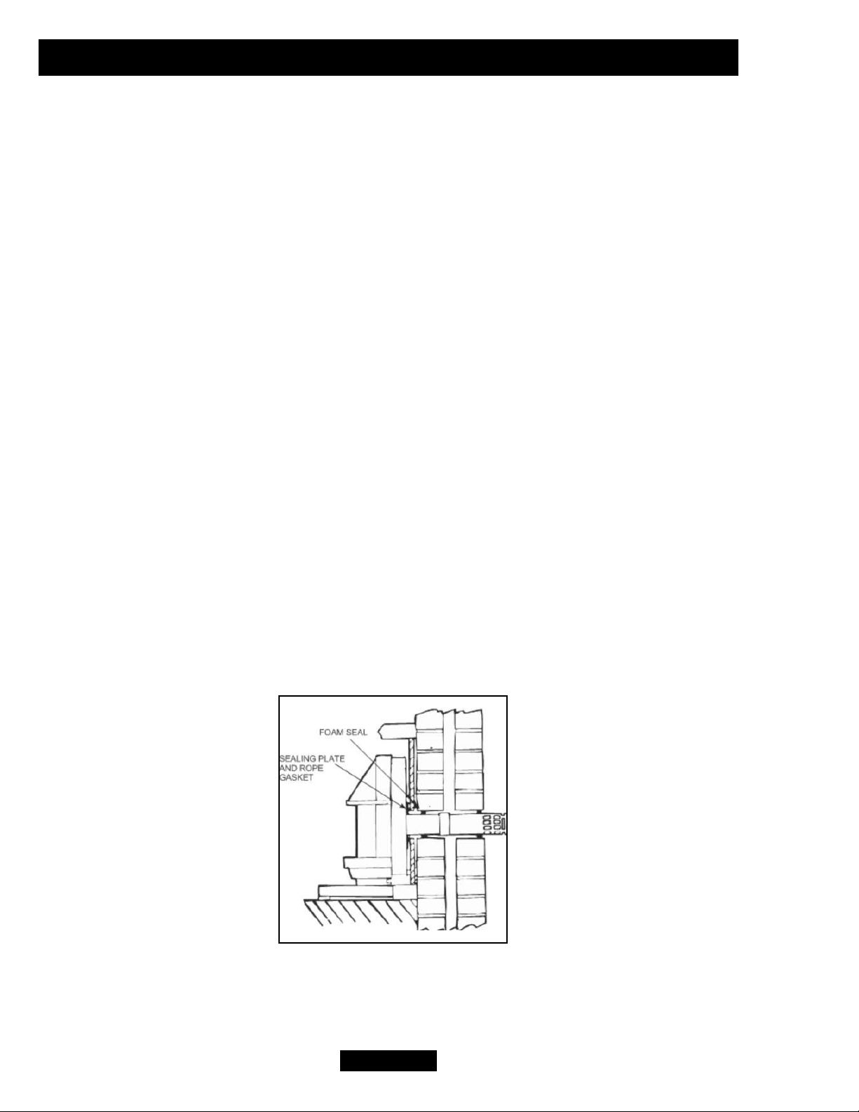
(c) FITTING IN A FIRE SURROUND (Fig. 1): The fire can be fitted in a compatible
fire surround having a standard gas fire cut-out or with a hole 135mm diameter to
accept the flue. The material of the surround must be suitable for 100 degC
application i.e. marked with the suffix ‘100’. The inside of the external wall should be
sealed off to prevent draught from the cavity into the room. A foam seal pack is
provided for this purpose. Wrap some of the foam seal around the inner air duct so
that when the fire is installed, the foam seal expands to prevent draught into the
room.
NOTES;
1. The foam seal starts to expand once the compression tape is removed. Hence
the foam seal should be put on only when the fire is ready to be installed.
2. When fixing the flue length, the wall thickness must be measured from the inner
face of the fire surround (Refer to Section 5.2).
Page 10
© GDC Group Ltd. 2014
INSTALLER GUIDE
FIG. 1
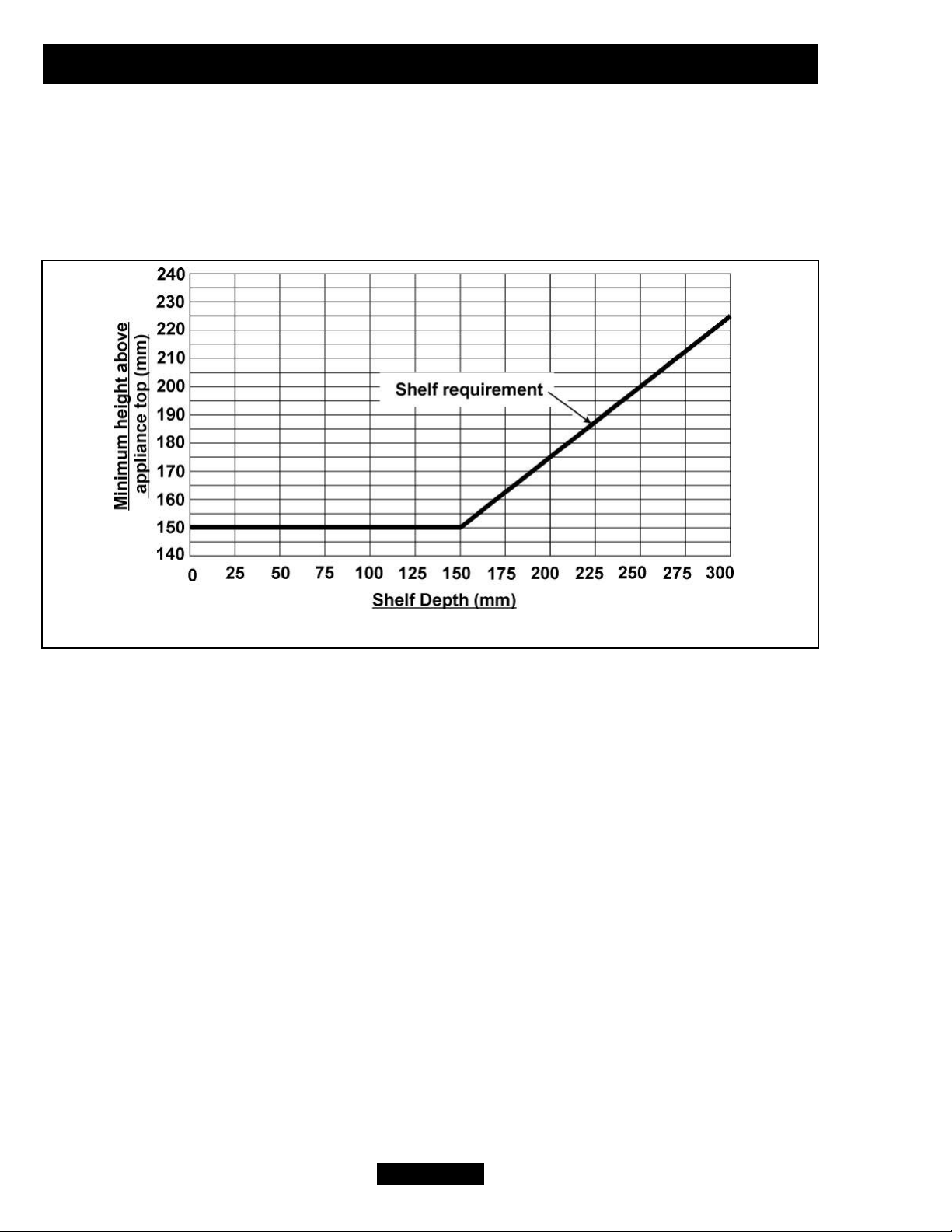
4.3 Fireplace clearances (See Fig. 2).
4.3.1 The minimum height from the extreme top surface of the fire to the underside of
any shelf made from wood or other combustible materials is as follows:
For a shelf up to 150mm deep
Minimum height from the extreme top surface of the fire = 150mm.
For a shelf deeper than 150mm
150mm + 12.5mm for every 25mm depth over 150mm.
There is no restriction on the depth of non-combustible projections but a space of at
least 30mm should be allowed above the top of the appliance to enable removal of
the fascia.
4.3.2.1 For combustible projections up to a depth of 178mm (Measured from the rear
fixing plane of the fire) a minimum clearance of 75mm should be maintained at the left
and right side of the fire. This is measured from the extreme side of the fascia. This
will allow easy access. This clearance is mandatory for temperature requirements.
4.3.2.2 For any combustible projections beyond 178mm (Measured from the rear
fixing plane of the fire) a minimum clearance of 100mm should be maintained at the
left and right side of the fire. This is measured from the extreme side of the fascia.
This clearance is mandatory for temperature requirements.
4.3.2.3 For non-combustible projections a minimum clearance of 75mm should be
maintained at the left and right side of the fire. This is measured from the extreme side
of the fascia. This will allow easy access.
If the fireplace opening is greater than the acceptable dimensions given in this guide,
do not use the back of a fire surround or marble to reduce the opening. This may
cause cracking of the surround back or marble.
Page 11
© GDC Group Ltd. 2014
FIG. 2 Combustible shelf clearances.
INSTALLER GUIDE
Page 12
© GDC Group Ltd. 2014
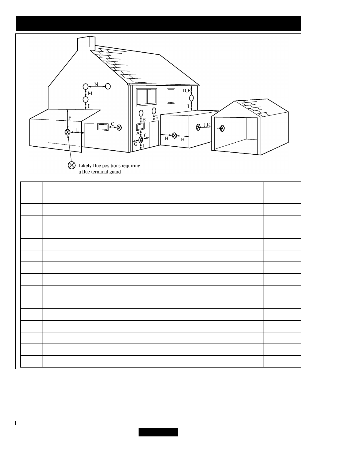
Key Terminal position
Minimum
distance.
A* Directly below an opening, air brick, opening window etc. 300mm
B* Above an opening, air brick, opening window etc. 300mm
C* Horizontally to an opening, air brick, opening window etc. 300mm
D Below gutters, soil pipes or drain pipes. 300mm
E Below eaves. 300mm
F Below balconies or car port roof. 600mm
G From a vertical drain pipe or soil pipe. 300mm
H** From an internal or external corner. 600mm
I Above ground, roof or balcony level. 300mm
J From a surface facing the terminal. 600mm
K From a terminal facing the terminal. 600mm
L From an opening in a car port (e.g. door, window) into dwelling. 1200mm
M Vertically from a terminal on the same wall. 1500mm
N Horizontally from a terminal on the same wall. 300mm
FIG. 3
*In addition, the terminal should not be nearer than 300mm to an opening in the
building fabric formed for the purpose of accommodating a built-in element such as
a window frame or door frame (See figure 4).
** The reference to external corners does not apply to building protrusions not
exceeding 450mm, such as disused chimneys on external walls.
INSTALLER GUIDE
 Loading...