

Valor 4190, 4191 Installer's Manual

F
t
INSTALLER GUIDE
MODEL 4190 (For Natural Gas)
MODEL 4191 (For Propane Gas)
Inset Live Fuel Effect
Gas Fires
with
UltimateFireslide
or
Fusion
ron
Please ke e p in a safe p l ac e for fut ur e r e fe r e n c e
600A917/03
1

Please leave this Installer Guide with the user
y
Model 4190 is for use with natural gas (G20)
Model 4191 is for use with propane gas (G31)
These appliances are for use in the United
Kingdom (GB) and the Republic of Ireland (IE)
onl
.
CUSTOMER CARE
This Installer Guide gives sufficient details to enable the appliance to be installed
and maintained. If further information is required, our Valor AdviceLine will
be pleased to hel p.
Please telephone 0345 626341 (Local call rates apply)
2

CONTENTS
Page
Appliance Data ........................................................................................................................................................... 4
General Installation Requirements............................................................................................................................ 4
Contents of Pack..............................................................................................................................................……. 8
Preliminary Ignition Check....................................................................................................................................... 9
Fireplace Requirements............................................................................................................................................. 10
Gas Supply Pipe.......................................................................................................................................................... 11
Preparing Appliance for Installation........................................................................................................................... 12
Convection Box Installation....................................................................................................................................... 13
Burner Installation..................................................................................................................................................... 15
Front Surround & Control Linkage Installation........................................................................................................ 16
Ceramic Coals & Walls Installation .......................................................................................................................... 17
Operating Checks....................................................................................................................................................... 20
• Fire Control Check.............................................................................................................................................
• Reference Pressure Check....................................................................................................................................
• Spillage Check......................................................................................................................................................
Final Review............................................................................................................................................................... 22
Servicing & Parts Replacement.................................................................................................................................. 23
• Ignition Microswitch ...........................................................................................................................................
• Gas Shut-off Microswitch ...................................................................................................................................
• Fire Front..............................................................................................................................................................
• Control Slide Button ...........................................................................................................................................
• Control Slide Unit................................................................................................................................................
• Electronic Ignition Generator .............................................................................................................................
• Thermocouple Interrupter Block.........................................................................................................................
• Burner Unit..........................................................................................................................................................
• Pilot Unit..............................................................................................................................................................
• Gas Shut-off Tap..................................................................................................................................................
• Gas Flow Rate Controller ....................................................................................................................................
• Injector - Main Burner.........................................................................................................................................
• Burner Plaques.....................................................................................................................................................
• Removing Appliance from Fireplace ...................................................................................................................
• Spare Parts - Short List ........................................................................................................................................
20
21
21
23
23
24
25
25
25
26
26
26
27
27
27
28
28
29
3

1. APPLIANCE D ATA
This product uses fuel effect pieces, burner compartment walls and gaskets containing
Refractory Ceramic Fibres (RCF), which are man-made vitreous silicate fibres.
Excessive exposure to these materials may cause temporary irritation to eyes, skin and
respiratory tract. Consequently, it makes sense to take care when handling these articles
to ensure that the release of dust is kept to a minimum. To ensure that the release of
fibres from thes e RCF articles is kept to a m inimum, during inst allation and servic ing
we recommend that you use a HEPA filtered vacuum to remove any dust and soot
accumulated in and around the fire before and after working on the fire. When replacing
these articles we recommend that the replaced items are not broken up, but are sealed
within a heavy duty poly thene bag , clearly lab elled as R CF wast e. This is not clas sified
as “hazardous waste” and may be disposed of at a tipping site licensed for the disposal of
industrial waste. Protective cl othing is no t required when handling th ese articles, but we
recomm end y ou follo w the norm al hygie ne rule s o f not s mo king, e ating or drinking in
the work area and always wash your hands before eating or drinking.
This appliance does not contain any component manufactured from asbestos or
asbestos related products.
The applia n c e data label is chain ed bel o w th e burner a nd is visibl e when the bottom
front cover is removed.
Model 4190 Model 4191
Gas Natural (G20) Propane (G31)
Inlet Pressu re 20mbar 37mbar
Input - Max. (Gross) 6.0kW (20,500Btu /h ) 6.1kW (20,800Btu/h)
Input - Min. (Gross) 2.7kW (9,200Btu/h) 4.3k W (14,650Btu/h)
Output - Ma x. 3.5kW (11,900Btu/h) 3.17kW (10,800Btu/h)
Output - Min 1.3kW (4,450Btu/h) 2.24k W (7,600Btu/h)
Burner Test Pressure
(Cold)
Gas Connection 8mm pipe 8mm pipe
Burner Injector Bray Cat. 82 Si ze 400 Bray Cat. 92 Si ze 190
Pilot & Atmosphere
Sensing Devi c e
Ignition Piezo Electric. Integral wi th
Aeration Non-adjustable Non-adjustable
17.0±0.75mbar (6.8±0.3in
w.g.)
SIT Ref. OP9030 SIT Ref. OPLPG9221
Gas Tap
36.0±0.75mbar
(14.45±0.3in w.g.)
Piezo Electric. Integral wi th
Gas Tap
2. GENERAL INSTALLATION REQUIREMENTS
2.1 The installation must be in accordance with these instructions.
For the user’s protection, in the United Kingdom it is the law that all gas appliances are
installed by competent persons in accordance with the current edition of the Gas Safety
(Installation and Use) Regulations. Failure to install the appliance correctly could lead
to prosecution. The Council for the Registration of Gas Installers (CORGI) requires
its members t o w ork to recognised stand ards.
In the United Kingdom the installation must also be in accordance with:
a) All the relevant parts of local regulations.
b) The current edition of the Building Regulations issued by the Department of the
Environmen t a nd the Welsh O ffice or th e Building Standar d s (Scotl and)
Regulat ions issu ed by the Scott ish Develo p ment Depar t ment.
c) All relevant codes of practice.
4
d) The relevant parts of the current editions of the following British
Standards:BS 715
BS 1251
BS 1289 Part 1
BS 1289 Part 2
BS 4543 Part 2
BS 5440 Part 1
BS 5440 Part 2
BS 5871 Part 2
BS 6461 Part 1
BS 6891
BS 8303
In the Republic of Ireland the installation must also conform with
the relevant parts of:
a) The current editi o ns of:-
** Does not apply to pre-cast flues - See
section 2.2.3
IS 813
ICP3
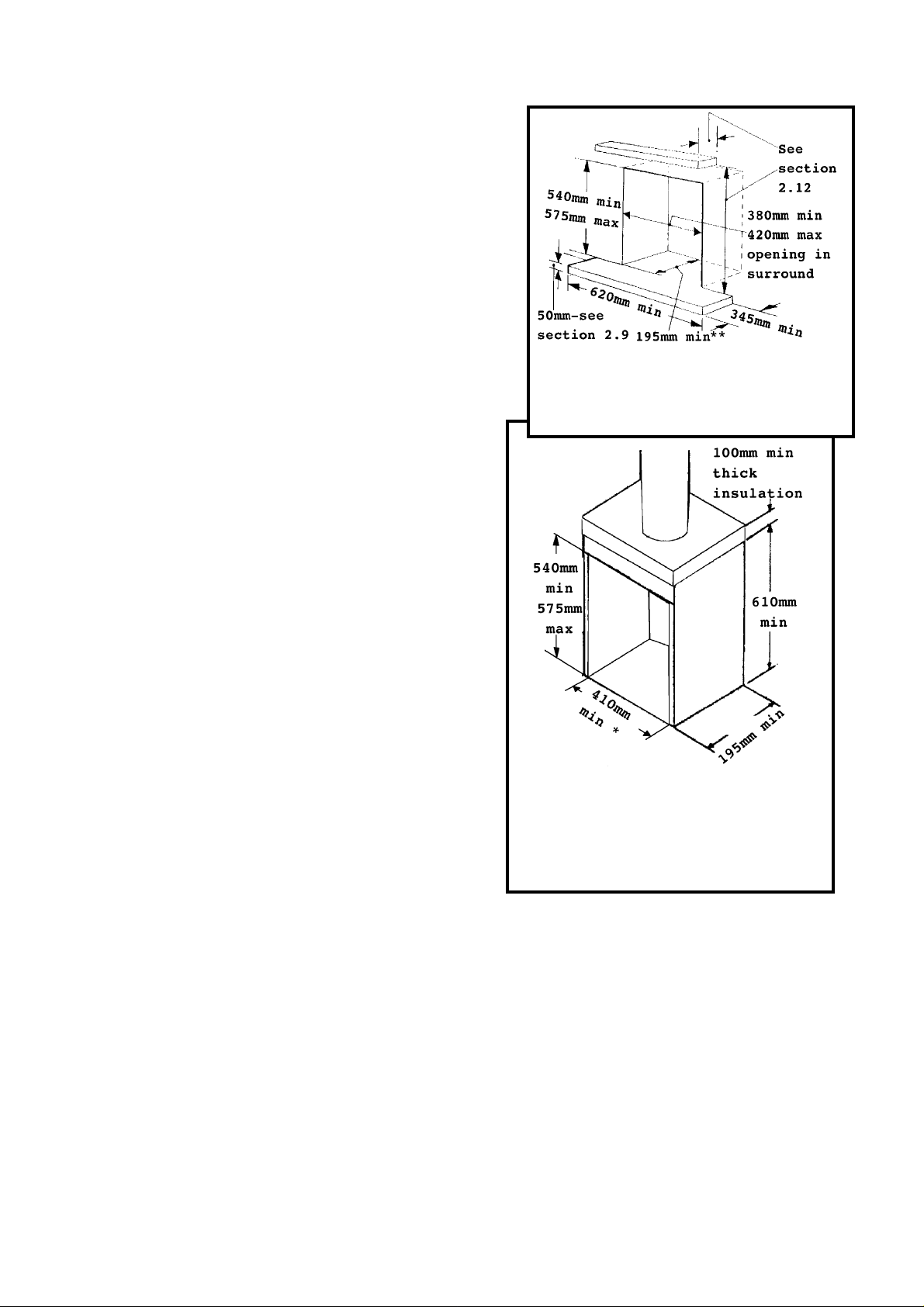
Fig. 1 Hearth & Fireplace Opening
IS327
b) All relevant national and local rules in force.
2.2 In the United Kingdom, as supplied, this appliance can be
installed in the following situations:-
2.2.1 To a fireplace complete with surround and hearth as shown
in figure 1 and c omplying with BS1251. The required fir epl ace,
hearth, debris catchment area a nd clearance di mensions are shown
in figure 1.
2.2.2 To a fireplace incorporating a twin walled metal flue box
complying with the constru ctional r equirements of th e c urrent
edition of BS 715 and standing on a non-co mbustible base The
dimensions of the flue box must conform to the opening shown
in figure 2. F or flue d etails see sectio ns 2.3 & 2.4.
2.2.3 To a fireplace that has a precast concrete or clay flue block
system conforming to BS1289. The a pplianc e i s suitable for
install ations conforming to ol der version s of BS1289 a s wel l as the
current edition. The flue blocks must have a minimum width not
less than 63mm and a cross-sectional area not less than
2
13,000mm
area of 13, 000mm
16,500mm
Older ed itions of BS1289 requir ed a cross-sec t ional
.
2
2
. The current revision of the standard requires
. This appliance is suitable in both cases. The total
depth of the open i ng measured from the fi n ished fr on t of the
fireplace (Including plaster, surround etc.) must be not less than
* If inte r n al width i s g r e ater th an 440mm the
opening width must be reduced to not more
than 40mm to ensure adeq u ate s e al ing to fire .
Fig. 2 Twin wall metal flue box
(Internal dimensions)
100mm.
The flu e starter blocks should no t be m odifi ed .
The current version of BS1289 recommend s that there sh ould be an a ir space or
insulation between the f l ue blocks and the plaster because heat tran sfer may cause
cracking on directly plastered flues. However, generally this appliance is suitable for
installati o ns und er all c ircu mst ances unless there is a history of c racki ng problems.
Remember that faults such as cracking may be caused by poorly built and restrictive
flues, e.g. mortar extrusions, too many bends, flue heights below three metres,
restrictive terminations, etc.
2.2.4 To a builder’s opening within the dimensions shown in figure 1.
5
2.3 Suitable flues and minimum flue sizes are as follows:a) 225mm x 225mm conventi onal bri c k flue.
b) 175mm diameter l ined bri c k or stone flu e.
c) 200mm diameter factor y ma de insul ated flu e ma nufactured to BS4543.
d) 175mm diameter flue pi pe. See BS6461 Part 1 f or suitable materia ls.
e) Single wall, twin wall or flexible flue liner with a minimum diameter of 125mm.
The materials to be used a re stainl ess steel or aluminium as specifi ed in BS715.
f) A properly constructed precast concrete or clay flue system conforming to
BS1289 Part 1 or 2. This system is only suitable when the co nditions stated in sec tion
2.2.3 are met.
2.3.1 It should be noted that, as with many appliances, sharp bends or horizontal runs
in metal f lues at the top of the system can be a cause of probl ems i n these types of
installation.
2.4 The minimum effective height of th e flue must be 3m.
2.5 The flue must not be used for any other appliance or application.
2.6 Any chimney damper or restrictor should be removed. If removal is not possible,
they must be secur ed in the open position.
2.7 If the appliance is intended to be installed to a chimney which was previously
used for solid fuel, the flue must be swept clean prior to installation. All flues should be
inspecte d for soundn ess and f reedom from block ages.
2.8 If the fireplace opening is an underfloor draught type, it must be sealed to stop
any draughts.
2.9 The appliance must be mounted behind a non-combustible hearth (n.b
conglomerate marble hearths are considered as non-combustible). The appliance can
be fitted to a purpose made pr oprietary class “O” 150°C surround. The hea rth materi a l
must be at least 12mm thick. The periphery of the hearth (or fender) should be at least
50mm above floor l evel to discourage the placi n g of carpets or r ugs over it.
The surfac e of the hearth must be suffi c i ently flat to enable the bottom of the front
surroun d , the burn er bracket an d th e bottom front cover c a sti ng to be aligned
horizontally. Any excessive unevenness (uneven tiles, Cotswold stone, etc.) should be
rectified.
The appliance must not stand on combustible
materials or carpets.
The appl i anc e must not be fi tte d d i r e c tly against
a combustible wall. If the applia nce is to be fitted
against a wa l l with combustible claddi ng, the cla d d ing
must be removed from the area c overed by the outer
surround (see figure 3). We suggest that the actual
surround is used as a template to mark the area for
combustible cladding removal.
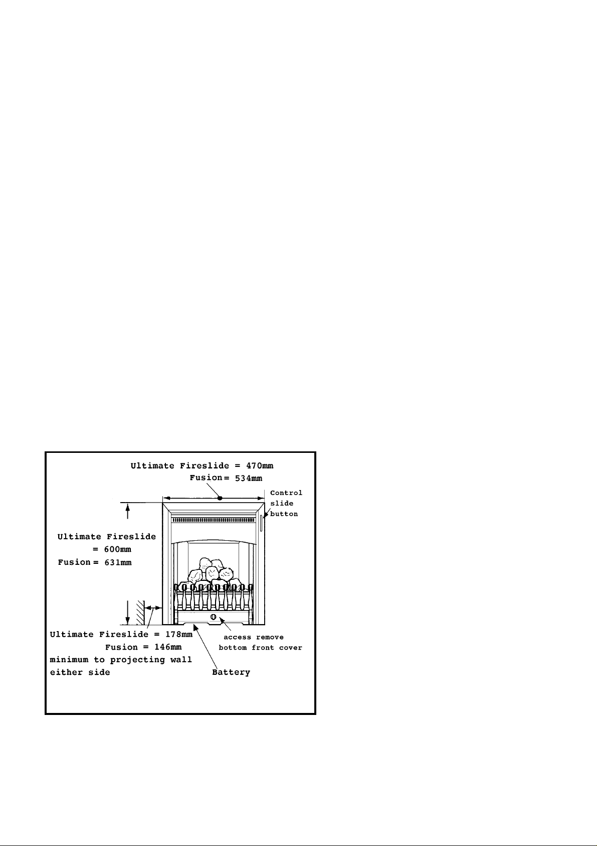
Fig 3 Front dimensions & side clearance to projections
2.12 The minimum height f rom the top surf ace of the hea rth to the un derside of any
shelf made f r om wood or other combu sti ble material s i s a s follows:-
• For a shelf up to 150mm deep
Minimum height = 750mm.
• For a shelf deeper than 150mm
750mm + 12.5mm for ever y 25mm depth over 150mm.
2.10 The minimum distan c e f rom the outsid e edge
of the fron t su rround to a corner wa ll or other
projection which extend s f u rther forw a r d than the
front of the appliance at either side is shown in
figure 3.
2.11 The front face of the fireplace should be
reasonabl y f lat over the area covered by th e c onvection
box top a nd sid e flan g e seals to ensure good sealin g .
These face s should b e m ade good if nec essary.
The fireplace floor should be reasonably flat to ensure
that a good seal with the convection box can be made.
6

2.13 Note that soft wall cover ings (e.g. embossed vinyl, etc .) are easi ly affected by
heat. They may scorch or become d i scoloured wh en c lose to a heatin g a ppl iance. Pl ease
bear this in mind when installing.
2.14 This appliance must not be installed in any room which contains a bath or
shower or where steam is regu larly pr esent.
2.15 An extractor fan may only be used in the same room as this appliance, or in any
area from which ventilation for the appliance is taken, if it does not affect the safe
performance of the appliance. Note the spillage test requirements detailed further on in
this manual. If the fan is likely to affect the appliance, the appliance must not be
installed unless the fan is permanently disconnected.
2.16 In the United K ingdom (GB) no special ventilation bricks or vents are required
in the room for this appliance.
In the Republic of Ireland (I.E.), permanent ventilation must comply with the
regulations currently in force.
2.17 Propane gas appliances must not be installed in a room which is built entirely
below groun d level (see BS 5871 Part 2).
7
3 UNPACKING & PRELIMINARY CHECKS
The items required for this appliance are contained in two packs.
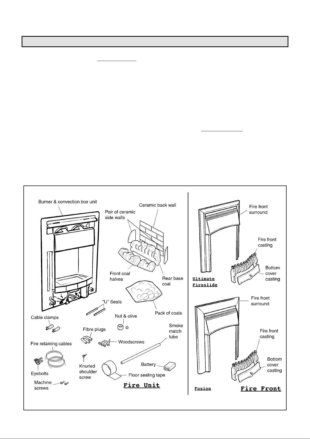
Pack 1 - Fire Unit contains:
1 Burner & Convection box Unit
with fron t surround
1 Nut & olive for 8mm inlet pipe
1 Ceramic back wall
1 Pair of ceramic side walls
1 Front base coal - left & right
halves
1Rear base coal
1 Pack of 7 loose coals
2 Small “U” seals for convec t ion
box side fla n ges
1 Strip of floor sealing tape
6Fibre plugs
4 Woodscrews
2 Fire retaining cables
2 Cable clamps
Carefully remove the contents. Take special care in handling the ceramic walls and the coals. Take care not to bend or
distort the slide control linkage when handling the fire front surround.
Check that all the listed parts are present and in good condition.
4Eyebolts
1 Knurled shoulder screw for
control linkage fixing
1 Installati on template
1 Battery
1 Smoke match tube
2 Machine screws for front
surround fixing
1 Literature pack
Pack 2 - Fire Front contains:
1 Fire front surround with
sliding control
1 Fire front casting
1 Bottom front cover casting
Fig. 4 Pack Contents
8
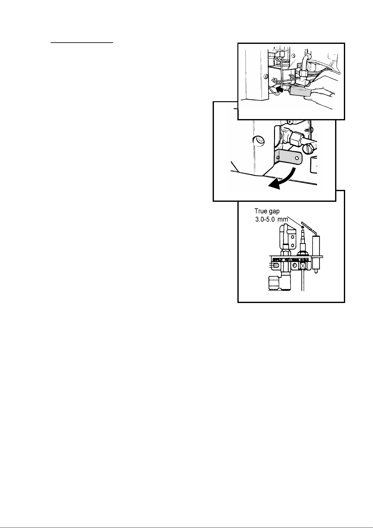
3.1 Check I gnition Sp ark
Before attemptin g to i nstall, i t is worth checki ng that the elec tr onic ignition
system perfo rms satisfactor ily.
3.1.1 Fit the battery to the ignition block located below the burner tray at
the left side (see figure 5). The positive terminal (+) is to the right as you
insert. The guide plate will help you to locate the battery
3.1.2 Rotate the control pivot bracket clockwise as far as it will go (see
figure 6). This should close the ignition circuit.
Sparks should be seen trac k ing from th e electrode pin to the
thermocoupl e tip (see figure 7).
If there are no spark s mak e the following checks.
a) Check condition of battery and that it is correctly fitted.
b) Check spark ga p between electrode wire and th ermocouple
tip (see figur e 7).
c) If a & b are satisfactory, check the ignition circuit and
components - see the servicing section in this manual
.
Fig. 6 Contr ol Pivot Rotation
Fig. 5 Batter y Fitting
Fig. 7 Pilot ignition system
9
 Loading...